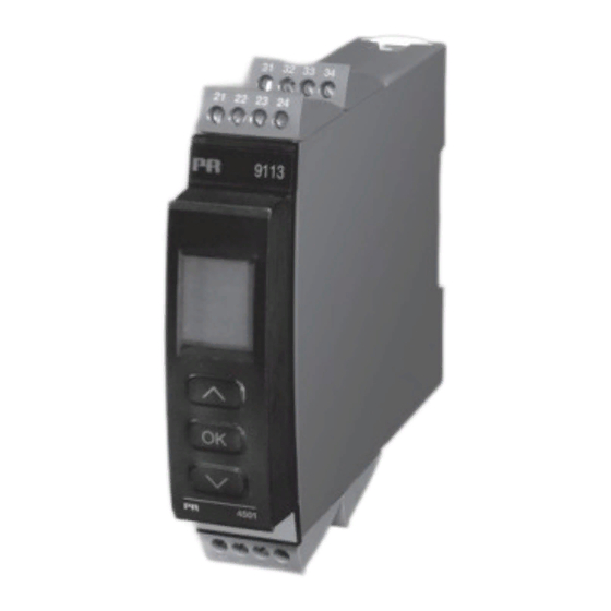
Seite 1
Side 1 Page 25 Page 51 Seite 77 9 1 1 3 T e m p e r a t u r e / m A c o n v e r t e r N o . 9 1 1 3 V 1 0 2 - I N ( 1 0 3 5 ) P r o d u c t v e r s i o n : 9 1 1 3 - 0 0 2 S I G N A L S T H E B E S T...
Seite 2
PR electronics A/S tilbyder et bredt program af analoge og digitale signalbehandlingsmoduler til industriel automation. Programmet består af Isolatorer, Displays, Ex-barrierer, Temperaturtransmittere, Universaltransmittere mfl. Vi har modulerne, du kan stole på i selv barske miljøer med elektrisk støj, vibrationer og temperaturudsving, og alle produkter opfylder de strengeste internationale standarder.
Seite 5
Hvis der er tvivl om modulets rette håndtering, skal der rettes henvendelse til den lokale forhandler eller alternativt direkte til: pR electronics A/s, lerbakken 10, 8410 Rønde, Danmark, tlf: +45 86 37 26 77. Det er ikke tilladt at benytte flerkoret ledning ved tilslutning af forsyningsspæn- ding med mindre ledningsenderne er forsynet med ledningstyller.
AnsvAR I det omfang instruktionerne i denne manual ikke er nøje overholdt, vil kunden ikke kunne rette noget krav, som ellers måtte eksistere i henhold til den indgå- ede salgsaftale, mod PR electronics A/S. AFmonTERIng AF sysTEm 9000 billede 1: Modulet frigøres fra DIN-skinnen ved...
En 60079-11 : 2007, En 60079-15 : 2005, En 60079-26 : 2007 ATEX certificate: KEmA 07ATEX0148 X Bemyndiget organ: KEmA Quality b.v. (0344) Utrechtseweg 310, 6812 AR Arnhem p.o. box 5185, 6802 ED Arnhem The netherlands Rønde, 24. september 2009 Kim Rasmussen Producentens underskrift 9113 - Product Version 9113-002...
• SIL 2-funktionaliteten skal aktivt tilvælges via menupunkt. Anvendelse • 9113 kan monteres i sikkert område samt i zone 2 / division 2 og modtage signaler fra zone 0, 1, 2, 20, 21 og 22 / Class I/II/III, Div. 1, Gr. A-G.
*Bestilles særskilt: CJC- klemme 5910Ex / 5913Ex Forsyning via Zone 0, 1, 2, power rail 20, 21, 22 / Cl. I/II/III, div. 1 gr. A-g Zone 2 / Cl. 1, div. 2, gr. A-D eller sikkert område 9113 - Product Version 9113-002...
Anvendelse • Kommunikationsinterface til ændring af driftsparametre i 9113. • Kan flyttes fra en 9113 til en anden 9113 og downloade opsætningen fra det første modul til andre af samme type. • Som fastmonteret display til visualisering af procesdata og status.
Statusrelæ til forsyning ......1,5 kVAC / 150 VAC forstærket Kommunikationsinterface ......Programmeringsfront 4501 Signal- / støjforhold ........Min. 60 dB (0...100 kHz) Gennemsnitlig reaktionstid inkl. forsinkelse: Temperaturindgang ......... ≤ 1 s mA-indgang ..........≤ 0,4 s Kalibreringstemperatur ........ 20...28°C 9113 - Product Version 9113-002...
Seite 12
Klemskruetilspændingsmoment ....0,5 Nm Relativ luftfugtighed ........< 95% RH (ikke kond.) Mål, uden displayfront (HxBxD) ....109 x 23,5 x 104 mm Mål, med displayfront (HxBxD) ....109 x 23,5 x 116 mm 9113 - Product Version 9113-002...
Seite 14
Max. spænding ........... 125 VAC / 110 VDC Max. strøm ..........0,5 AAC / 0,3 ADC Max. effekt ........... 62,5 VA / 32 W marine-godkendelse: Det Norske Veritas, Ships & Offshore ..Ansøgt 9113 - Product Version 9113-002...
Seite 15
FM us ............FM 3600, 3611, 3810 CSA E60079-0, -15 CSA 22.2 -25, -142, -213 ANSI/ISA-12.00.01 / 12.12.02 UL, Standard for Safety ......UL 61010-1 SIL ............... IEC 61508 af span = af det aktuelt valgte måleområde 9113 - Product Version 9113-002...
Føler kortslutning SE.SH Se grænser ovenfor Intern CJC-føler defekt eller CJC- Test af intern CJC-føler CJ.ER temperatur uden for område** Defekt eller manglende CJC- CJC-klemme fejl - check CJC-terminal CJ.CE klemme, temperatur uden for gyldigt område 9113 - Product Version 9113-002...
Seite 17
** Fejlen kan resettes ved at steppe igennem menuerne eller ved at slukke og tænde for modulet. Fejlen kan tilsidesættes ved at vælge en anden indgangstype end TC. *** Fejlen kan resettes ved at steppe igennem menuerne. 9113 - Product Version 9113-002...
AF TRyKKnAppER Dokumentation til rutediagram generelt Når du skal konfigurere 9113, bliver du guidet igennem samtlige parametre og kan vælge netop de indstillinger, der passer til applikationen. Til hver menu findes en rullende hjælpetekst, som vises i displaylinie 3.
FR, IT, ES, SE og DK. power rail: I menuen ”RAIL” vælges om følerfejl skal overføres til en central overvågning i PR 9410 power control unit. safety Integrity level: Se Safety Manual for yderligere information. 9113 - Product Version 9113-002...
TC.J TC.E password. TC.K Rød tekst viser safety SENSOR TC.TYPE Txt 10 Txt 18 Txt 36 parametre i en SIL- konfiguration. Se Safety Manual for yderligere information. Fortsættes på siden Rutediagram ADV.SET ADV.SET Txt 2 9113 - Product Version 9113-002...
Seite 24
999.9 999.9 -199.9 -199.9 Konfiguration af 150.0 Til normaltilstand 1.0 OUT.LO OUT.HI RESP. magen til CH1 Txt 14 Txt 15 Txt 35 9113 - Product Version 9113-002...
Vælg Pt-følertype Gå til displayopsætning [06] Vælg Pt10 som følertype Udfør memory-operationer Vælg Pt20 som følertype Overfør gemt opsætning til 9113 Vælg Pt50 som følertype [18] Gem 9113-opsætning i 4501 Vælg Pt100 som følertype Juster LCD-kontrast Vælg Pt200 som følertype [19] Vælg Pt250 som følertype...
Seite 27
Scrolling help texts in display line 3 ........49 Appendix ................102 IECEx Installation Drawing ..........103 ATEX Installation Drawings, UK, FR, DE, DK ....106 FM Installation Drawing ..........118 Safety Manual ..............121 9113 - Product Version 9113-002...
General mounting, connection and disconnection of wires. Troubleshooting the device. Repair of the device and replacement of circuit breakers must be done by pR electronics A/s only. WARnIng Do not open the front plate of the device as this will cause damage to the connector for the display / programming front PR 4501.
Seite 29
Should there be any doubt as to the correct handling of the device, please contact your local distributor or, alternatively, pR electronics A/s, lerbakken 10, 8410 Rønde, Danmark tlf: +45 86 37 26 77. The use of stranded wires is not permitted for mains wiring except when wires are fitted with cable ends.
To the extent the instructions in this manual are not strictly observed, the customer cannot advance a demand against PR electronics A/S that would otherwise exist according to the concluded sales agreement. hoW To DEmoUnT sysTEm 9000...
En 60079-11 : 2007, En 60079-15 : 2005, En 60079-26 : 2007 ATEX certificate: KEmA 07ATEX0148 X Notified body KEmA Quality b.v. (0344) Utrechtseweg 310, 6812 AR Arnhem p.o. box 5185, 6802 ED Arnhem The netherlands Rønde, 24 September 2009 Kim Rasmussen Manufacturer’s signature 9113 - Product Version 9113-002...
0, 1, 2, 20, 21 and 22 / Class I/II/III, Div. 1, Gr. A-G. • Conversion and scaling of temperature (Pt, Ni and TC) and active current signals. • The 9113 has been designed, developed and certified for use in SIL 2 applications according to the requirements of IEC 61508. Technical characteristics •...
*Order separately: CJC connetor 5910Ex/5913Ex Supply via Zone 0, 1, 2, power rail 20, 21, 22 / Cl. I/II/III, div. 1 Zone 2 / Cl. 1, div. 2, gr. A-D or safe area gr. A-g 9113 - Product Version 9113-002...
Application • Communications interface for modification of operational parameters in 9113. • Can be moved from one 9113 device to another and download the configuration of the first unit to subsequent units. • When mounted in the process, the display shows process values and device status.
Status relay to supply ......1.5 kVAC / 150 VAC reinforced Communications interface ......Programming front 4501 Signal / noise ratio ........Min. 60 dB (0...100 kHz) Average response time incl. delay: ≤ Temperature input ........≤ mA input ..........0.4 s Calibration temperature....... 20...28°C 9113 - Product Version 9113-002...
Seite 36
Screw terminal torque ......... 0.5 Nm Relative humidity ......... < 95% RH (non-cond.) Dimen., without display front (HxBxD) ..109 x 23.5 x 104 mm Dimensions, w. display front (HxBxD) ..109 x 23.5 x 116 mm 9113 - Product Version 9113-002...
Seite 38
Max. voltage ..........125 VAC / 110 VDC Max. current ..........0.5 AAC / 0.3 ADC Max. AC power ........... 62.5 VA / 32 W marine approval: Det Norske Veritas, Ships & Offshore ..Pending 9113 - Product Version 9113-002...
Seite 39
FM us ............FM 3600, 3611, 3810 CSA E60079-0, -15 CSA 22.2 -25, -142, -213 ANSI/ISA-12.00.01 / 12.12.02 UL, Standard for Safety ......UL 61010-1 SIL ............... IEC 61508 of span = of the currently selected measurement range 9113 - Product Version 9113-002...
See conditions above Internal CJC sensor defect or Test of internal CJC sensor CJ.ER CJC temperature out of range** Defect or missing CJC-connector, CJC connector error - check CJC-connector block CJ.CE temperature out of allowed range 9113 - Product Version 9113-002...
Seite 41
** Error is acknowledged by either stepping through the basic setup, or by resetting the device power. Error can be disregarded by selecting input type different than TC. *** Error is acknowledged by stepping through the basic setup. 9113 - Product Version 9113-002...
Documentation for routing diagram. In general When configuring the 9113, you will be guided through all parameters and you can choose the settings which fit the application. For each menu there is a scrolling help text which is automatically shown in line 3 on the display.
The simulation function exits automatically, if the 4501 is detached. password: Here you can choose a pass word between 0000 and 9999 in order to protect the device against unauthorised modifications to the configuration. The device is delivered default without password. 9113 - Product Version 9113-002...
Seite 47
UK, DE, FR, IT, ES, SE and DK. power rail: In the menu ”RAIL” you can choose if sensor errors are transmitted to the central surveillance in the PR 9410 power control unit. safety integrity level: See Safety Manual for details 9113 - Product Version 9113-002...
TC.K SENSOR TC.TYPE Red text signifies safety Txt 10 Txt 18 Txt 36 parameters in a SIL configuration. See safety manual for details Continued on the page Routing diagram ADV.SET ADV.SET Txt 2 9113 - Product Version 9113-002...
Seite 49
999.9 999.9 -199.9 -199.9 Configuration of 150.0 To default state 1.0 OUT.LO OUT.HI RESP. identical to CH1 Txt 14 Txt 15 Txt 35 9113 - Product Version 9113-002...
Seite 53
Reglage avance (ADV.SET) ..........74 Menu deroulant en ligne 3 de l’indicateur......75 Appendix ................102 IECEx Installation Drawing ..........103 ATEX Installation Drawings, UK, FR, DE, DK ....106 FM Installation Drawing ..........118 Safety Manual ..............121 9113 - Product Version 9113-002...
électrostatiques (ESD) : montage général, raccordement et débranchement de fils et recherche de pannes sur le module. seule pR electronics sARl est autorisée à réparer le module et à remplacer les fusibles. AvERTIssEmEnT Ne pas ouvrir la plaque avant du module au risque d’endommager...
Seite 55
Vous pouvez également vous adresser à PR electronics SARL, Zac du Chêne, Activillage, 4, allée des Sorbiers, F-69673 Bron Cedex (tél. : (0) 472 140 607) ou à PR electronics A/S, Lerbakken 10, DK-8410 Rønde, Danemark (tél. : +45 86 37 26 77).
Dans la mesure où les instructions de ce guide ne sont pas strictement respectées par le client, ce dernier n’est pas en droit de faire une réclamation auprès de PR electronics SARL, même si cette dernière figure dans l’accord de vente conclu.
Certificat ATEX : KEmA 07ATEX0148 X Organisme notifié KEmA Quality b.v. (0344) Utrechtseweg 310, 6812 AR Arnhem p.o. box 5185, 6802 ED Arnhem The netherlands Rønde, le 24 septembre 2009 Kim Rasmussen Signature du fabricant 9113 - Product Version 9113-002...
• Conversion et mise à l’échelle de signaux en température (Pt, Ni et TC) et en courant actif. • Le 9113 a été conçue, développé et certifié pour utilisation dans les applications SIL 2 en conformité avec les exigences de la CEI 61508.
• L’accès à la programmation peut être bloqué par un mot de passe. Ce mot de passe est sauvegardé dans le module afin d’assurer un haut niveau de protection contre les modifications non autorisées. montage / installation • Cliquer le 4501 sur la face avant du 9113 9113 - Product Version 9113-002...
Interface de communication ....... Façade de programmation 4501 Rapport signal / bruit ........Min. 60 dB (0...100 kHz) Temps de réponse moyen, délai inclu : ≤ Entrée température ......... ≤ Entrée mA ..........0,4 s Température d’étalonnage ......20...28°C 9113 - Product Version 9113-002...
Seite 62
Pression max. avant déformation de la vis . 0,5 Nm Humidité relative.......... < 95% RH (sans cond.) Dimensions, sans façade 4501 (HxLxP) ..109 x 23,5 x 104 mm Dimensions, avec façade 4501 (HxLxP) ..109 x 23,5 x 116 mm 9113 - Product Version 9113-002...
Seite 64
Tension max..........125 Vca / 110 Vcc Courant max..........0,5 Aca / 0,3 Acc Puissance ca max........62,5 VA / 32 W Approbation marine : Det Norske Veritas, Ships & Offshore ..En cours 9113 - Product Version 9113-002...
Seite 65
IEC 61241-0 et -11 c FM us ............FM 3600, 3611, 3810 CSA E60079-0, -15 CSA 22.2 -25, -142, -213 ANSI/ISA-12.00.01 / 12.12.02 UL, Standard for Safety ......UL 61010-1 SIL ............... IEC 61508 EC = Echelle configurée 9113 - Product Version 9113-002...
Voir conditions ci-dessus Défaut capteur CSF interne ou temp. Vérification du capteur CSF interne CJ.ER CSF dépasse l’échelle** Bornier CSF en défaut ou manquant, Erreur connecteur CSF - contrôler le bornier CSF CJ.CE température dépasse l’échelle valable 9113 - Product Version 9113-002...
Seite 67
** L’erreur est corrigée soit en parcourant les menus, soit en déconnectant et puis reconnectant l’alimentation du module. L’erreur peut être négligée en sélectant un type d’entrée autre que TC. *** L’erreur est corrigée en parcourant les menus. 9113 - Product Version 9113-002...
Documentation pour le diagramme de programmation. généralités Lors de la configuration du 9113 vous êtes guidés tout au long des paramètres du menu ; ainsi vous pouvez choisir le réglage qui correspond à votre application. Pour chaque menu il y a un texte d’aide qui défile en ligne 3 de l’indicateur.
100%) est appliquée et la valeur actuelle est entrée. Si vous validez ces points, l’appareil va fonctionner selon cet ajustement. Si plus tard vous souhaitez modifier ou changer de type d’entrée l’unité reviendra à la calibration usine. 9113 - Product Version 9113-002...
Seite 73
Rail d’alimentation : Dans le menu ”RAIL” vous pouvez choirsir si des erreurs capteur doivent être transmis à l’unité de surveillance du module PR 9410 Contrôleur d’alimentation. safety Integrity level: Voir le ”Safety Manual” (en Anglais) pour informations complémentaires. 9113 - Product Version 9113-002...
Texte rouge signifie Txt 10 Txt 18 Txt 36 paramètres sécurité dans une configuration SIL. Voir le ”Safety Manual” (en Anglais) pour informations complémentaires. Continué à la page Diagramme de programmation ADV.SET ADV.SET Txt 2 9113 - Product Version 9113-002...
Seite 75
999.9 999.9 -199.9 -199.9 Configuration 150.0 de la voie 2 Retour au menu 1.0 OUT.LO OUT.HI RESP. identique Txt 14 Txt 15 Txt 35 à la voie 1 9113 - Product Version 9113-002...
[50] Erreur CSF - contrôler le bornier CSF [14] [51] Régler température de la sortie analogique basse Pas de communication [15] Régler température de la sortie analogique haute [16] Activer signal d’état du rail d’alimentation 9113 - Product Version 9113-002...
Installation, Montage und Demontage von Leitungen. Fehlersuche im Gerät. Reparaturen des gerätes und Austausch von sicherungen dürfen nur von pR electronics A/s vorgenommen werden. WARnUng Die Frontplatte des Gerätes darf nicht geöffnet werden, weil hier durch die Kontakte zur Kontaktierung des Frontdisplays 4501 beschädigt werden können.
Händler vor Ort Kontakt aufnehmen. Sie können aber auch direkt mit pR electronics gmbh, Im Erlengrund 26, D-46149 oberhausen, (Tel.: (0) 208 62 53 09-0) oder mit pR electronics A/s, lerbakken 10, DK-8410 Rønde, Dänemark (Tel.: +45 86 37 26 77) Kontakt aufnehmen.
Wasser leicht angefeuchtet ist. hAFTUng In dem Umfang, in welchem die Anweisungen dieses Handbuches nicht genau eingehalten werden, kann der Kunde PR electronics gegenüber keine Ansprüche geltend machen, welche ansonsten entsprechend der eingegange- nen Verkaufsvereinbarungen existieren können.
En 60079-11 : 2007, En 60079-15 : 2005, En 60079-26 : 2007 ATEX-Zertifikat: KEmA 07ATEX0148 X Zulassungsstelle: KEmA Quality b.v. (0344) Utrechtseweg 310, 6812 AR Arnhem p.o. box 5185, 6802 ED Arnhem The netherlands Rønde, 24. September 2009 Kim Rasmussen Unterschrift des Herstellers 9113 - Product Version 9113-002...
A-G aufnehmen. • Umwandlung und Skalierung von Temperatursignalen (Pt, Ni und TE) sowie aktiven Stromsignalen. • Der 9113 wurde entwickelt und zertifiziert für SIL 2-Anwendungen entsprechend den Anforderungen der Richtlinie IEC 61508. Technische merkmale • 1 grüne und 2 rote Leuchtdioden in der Front des Gerätes zeigen den normalen Betrieb und Fehlfunktionen an.
Bitte die CJC-Anschlussklemme Typ 5910Ex/ 5913Ex separat bestellen! Versorgung über Zone 0, 1, 2, Power Rail 20, 21, 22 / Cl. I/II/III, div. 1 gr. A-g Zone 2 / Cl. 1, div. 2, gr. A-D oder sicheres bereich 9113 - Product Version 9113-002...
Anwendungen • Kommunikationsschnittstelle zur Änderung der operativen Parameter im 9113. • Kann von einem 9113 auf das nächste gesteckt werden um die Daten des ersten Messumformers auf den nächsten zu übertragen. • Wenn das Gerät im Prozess integriert ist, zeigt das Display die entsprechen- den Prozesswerte und den jeweiligen Prozessstatus an.
Statusrelais zur Versorgung ....1,5 kVAC / 150 VAC verstärkt Kommunikationsschnittstelle ...... Programmierfront 4501 Signal- / Rauschverhältnis ......Min. 60 dB (0...100 kHz) Durchschnittliches Ansprechzeit inkl. Verzögerung: ≤ Temperatur-Eingang ........ ≤ mA-Eingang ..........0,4 s Kalibrierungstemperatur ......20...28°C 9113 - Product Version 9113-002...
Seite 88
Litzendraht Klemmschraubenanzugsmoment ....0,5 Nm Relative Luftfeuchtigkeit ......< 95% RF (nicht kond.) Abmessungen, ohne Frontdisplay (HxBxD) .. 109 x 23,5 x 104 mm Abmessungen, mit Frontdisplay (HxBxD) ... 109 x 23,5 x 116 mm 9113 - Product Version 9113-002...
Seite 90
Max. Spannung ........... 125 VAC / 110 VDC Max. Strom ..........0,5 AAC / 0,3 ADC Max. Leistung ..........62,5 VA / 32 W marine-Zulassung: Det Norske Veritas, Ships & Offshore ..Angefordert 9113 - Product Version 9113-002...
Seite 91
FM us ............FM 3600, 3611, 3810 CSA E60079-0, -15 CSA 22.2 -25, -142, -213 ANSI/ISA-12.00.01 / 12.12.02 UL, Standard for Safety ......UL 61010-1 SIL ............... IEC 61508 d. messspanne = der momentan gewählten Messspanne 9113 - Product Version 9113-002...
Sensor Kurzschluss SE.SH Siehe Bedingungen oben Interner CJC-Fühler defekt oder Test des internen CJC-Fühlers CJ.ER Temp. außerh. des Bereichs** Defekte oder fehlende CJC- CJC-Anschlussklemmen-Fehler - überprüfe CJC- CJ.CE Anschlussklemme, Temperatur Klemmenblock außerhalb des zulässigen Bereiches 9113 - Product Version 9113-002...
Seite 93
Einige Fehler können nur durch Wegnahme der Versorgungsspannung zurück gesetzt werden. ** Fehler wird entweder durch Durchschalten der Grundeinstellungen oder durch Wegnahme der Versorgungsspannung zurück gesetzt! Fehler greift nur bei TE-Eingang. *** Fehler wird durch Durchschalten der Grundeinstellungen zurück gesetzt. 9113 - Product Version 9113-002...
Dokumentation für das Flussdiagramm. grundsätzliches Bei der Konfiguration des 9113 werden Sie durch alle Parameter geleitet und Sie können die Einstellungen wählen, welche zur Applikation passt. Für jedes Menü existiert ein scrollender Hilfetext welcher automatisch in der 3. Zeile im Display gezeigt wird.
Wert wird übernommen. Dann wird ein höherer Wert (nicht unbedingt 100%) eingelesen. Wenn Sie die Kalibrierung akzeptieren, wird das Gerät mit den neuen Werten übernommen. Wenn Sie später diese Werte verwerfen oder andere Parameter eingeben, wird die Werkskalibrierung übernommen. 9113 - Product Version 9113-002...
Seite 99
Rail: Im Menü ”Rail” können Sie wählen, ob Sensor-Fehler an die zentrale Überwachung im Power Control Unit PR 9410 weitergegeben werden sollen. safety Integrity level (sIl): Für Details sehen Sie bitte im Sicherheitshandbuch (Safety Manual) nach. 9113 - Product Version 9113-002...
Seite 100
Passwort gesichert ist TC.K SENSOR TC.TYPE Txt 10 Txt 18 Txt 36 Roter Text bedeutet Sicher- heitsparameter in einer SIL Konfiguration. Siehe Sicherheitshandbuch (Safety Manual) für Details. Fortsetzung auf Seite 96 Flussdiagramm ADV.SET ADV.SET Txt 2 9113 - Product Version 9113-002...
Seite 101
999.9 999.9 -199.9 -199.9 Konfiguration von 150.0 Kanal 2 Zum Normal-Zustand 1.0 OUT.LO OUT.HI RESP. identisch zum Txt 14 Txt 15 Txt 35 Kanal 1 9113 - Product Version 9113-002...
For Installation in Zone 2 / Division 2 the following must be observed. The 4501 programming module is to be used solely with PR electronics modules. It is important that the module is undamaged and has not been altered or modified in any way. Only 4501 modules free of dust and moisture shall be installed.
Seite 106
Do not separate connectors when energized and an explosive gas mixture is present. Do not mount or remove modules from the Power Rail when an explosive gas mixture is present. Revision date: Version Revision: Prepared by: Page: 2009-11-27 V3 R0 9113 - Product Version 9113-002...
Seite 107
80 mW Lo/Ro 445 μH/ 0.3 F 1.6 F 8 F 80 mH 250 mH 600 mH 10 V 30 mA 15 nF 1.7 μH Revision date: Version Revision: Prepared by: Page: 2009-11-27 V3 R0 9113 - Product Version 9113-002...
Seite 109
Do not separate connectors when energized and an explosive gas mixture is present. Do not mount or remove modules from the Power Rail when an explosive gas mixture is present. Revision date: Version Revision: Prepared by: Page: 2009-11-27 V3 R0 9113 - Product Version 9113-002...
Seite 110
80 mW Lo/Ro 445 μH/ 0.3 F 1.6 F 8 F 80 mH 250 mH 600 mH 10 V 30 mA 15 nF 1.7 μH Revision date: Version Revision: Prepared by: Page: 2009-11-27 V3 R0 9113 - Product Version 9113-002...
Seite 112
Ne déconnecter pas les connecteurs une fois activé et dans un environnement en présence de gaz. Ne montez pas ou n'enlevez pas les modules du rail d’alimentation est présence d’un mélange de gaz. Revision date: Version Revision: Prepared by: Page: 2009-11-27 V3R0 – FR01 9113 - Product Version 9113-002...
Seite 113
80 mW Lo/Ro 445 μH/ 0,3 F 1,6 F 8 F 80 mH 250 mH 600 mH 10 V 30 mA 15 nF 1,.7μH Revision date: Version Revision: Prepared by: Page: 2009-11-27 V3R0 – FR01 9113 - Product Version 9113-002...
4501 Für die Installation in Zone 2 / Division 2 ist Folgendes zu beachten: Das aufsteckbare Frontdisplay 4501 zur Programmierung ist ausschließlich mit PR electronics- Geräten zu verwenden. Es ist wichtig, dass das Display unbeschädigt ist, nicht umgebaut oder in irgendeiner Weise verändert wurde.
Seite 115
Nicht die Anschlüsse trennen, solange ein Energie geladenes explosives Gasgemisch vorhanden ist. Montieren oder entfernen Sie nicht Geräte oder Baugruppen auf bzw. von der Power Rail, wenn ein explosives Gasgemisch vorhanden ist. Revision date: Version Revision: Prepared by: Page: 2009-11-27 V3R0 – DE01 9113 - Product Version 9113-002...
Seite 116
80 mW Lo/Ro 445 μH/ 0,3 F 1,.6 F 8 F 80 mH 250 mH 600 mH 10 V 30 mA 15 nF 1,7 μH Revision date: Version Revision: Prepared by: Page: 2009-11-27 V3R0 – DE01 9113 - Product Version 9113-002...
Seite 118
Monter/demonter ikke stik, når forsyning er tilsluttet og der forefindes en eksplosionsfarlig gasblanding. Monter/demonter ikke modulet på Power Rail, når der forefindes en eksplosionsfarlig gasblanding. Revision date: Version Revision: Prepared by: Page: 2009-11-27 V3R0 – DK01 9113 - Product Version 9113-002...
Seite 119
80 mW Lo/Ro 445 μH/ 0,3 F 1,6 F 8 F 80 mH 250 mH 600 mH 10 V 30 mA 15 nF 1,7μH Revision date: Version Revision: Prepared by: Page: 2009-11-27 V3R0 – DK01 9113 - Product Version 9113-002...
For Installation in Zone 2 / Division 2 the following must be observed. The 4501 programming module is to be used solely with PR electronics modules. It is important that the module is undamaged and has not been altered or modified in any way.
Seite 121
Warning: Do not mount or remove modules from the Power Rail when an explosive gas mixture is present. Revision date: Version Revision: Prepared by: Page: 2009-11-27 V3 R0 9113 - Product Version 9113-002...
Seite 122
Group A,B Group C,E,F Group D,G 0.3 F 1.6 F 8 F 80 mH 250 mH 600 mH 10 V 30 mA 15 nF 1.7 μH Revision date: Version Revision: Prepared by: Page: 2009-11-27 V3 R0 9113 - Product Version 9113-002...
9113 TeMpeRaTuRe / ma CONVeRTeR Safety Manual Observed standards Standard Description Functional Safety of electrical / electronic / programmable electronic IeC 61508 safety-related systems IeC 61508- part 2: Requirements for electrical / electronic / programmable electronic 2:2000 safety-related systems IeC 61508- part 3: Software requirements 3:1998 IeC 61326-3- Immunity requirements for safety-related systems 1:2008 acronyms and abbreviations acronym / Designation Description abbreviation Term defined by IeC 61508 as “part of a subsystem comprising a single component or any element group of components that performs one or more element safety functions” This is the likelihood of dangerous safety function probability of Failure pFD failures occurring on demand. on Demand The term “probability” is misleading, as IeC probability of danger- 61508 defines a Rate. ous Failure per Hour...
Safety Manual 9113 TeMpeRaTuRe / ma CONVeRTeR assumptions and restrictions for use of the product Basic safety specifications Operational temperature range.... -20...+60°C Storage temperature range...... -20...+85°C power supply type, min...... Double or reinforced Supply voltage ......... 19.2...31.2 VDC external loop supply voltage .... 5...26 VDC + external drop Mounting area .......... Zone 2 / Division 2 or safe area Mounting environment ...... pollution degree 2 or better Safety accuracy The analogue output corresponds to the applied input within the safety accuracy. Safety accuracy ........ ±2% 4.2.1 minimum span For temperature measurements, the selected range (OuT.HI - OuT.LO)
SIL-mode is entered, in addition to the normal functional test. Refer to section 14 - Safe parameterisation - user responsibility. 4.3.4 analogue output The connected safety pLC shall be able to detect and handle the fault indications on the analogue output of the 9113 converter by having a NaMuR Ne43-compliant current input. failure rates The basic failure rates from the Siemens standard SN 29500 are used as the failure rate database.
Safety Manual 9113 TeMpeRaTuRe / ma CONVeRTeR Safety parameters probability of dangerous Failure per Hour (pFH) 6.10e-08 Note probability of failure on demand (pFD) - 3.96e-04 1 year proof test interval proof test interval (10% of loop pFD) 3 years Safe Failure Fraction 90.7 % Demand response time Signal input: < 0.5 seconds Temperature input: < 1.1 seconds Demand mode High Demand rate 3000 seconds Mean Time To Repair (MTTR) 24 hours Diagnostic test interval 30 seconds Hardware Fault Tolerance (HFT) Component Type SIL capability SIL 2 Description of the “Safe State” Output ≤ 3.6 ma or output ≥ 21 ma Note1: The 9113 contains no lifetime limiting components, therefore the pFH figures are valid for up to 12 years, according to IeC 61508. Hardware and software configuration all configurations of software and hardware versions are fixed from factory, and cannot be changed by end-user or reseller.
Repair of the device and replacement of circuit breakers must be done by pR electronics a/S only. 12 maintenance No maintenance required. 13 Documentation for routing diagram The routing diagram is shown in section 16.2. 13.1 In general When configuring the 9113, you will be guided through all parameters and you can choose the settings which fit the application. For each menu there is a scrolling help text which is automatically shown in line 3 on the display. Configuration is carried out by use of the 3 function keys: 1 will increase the numerical value or choose the next parameter 2 will decrease the numerical value or choose the previous parameter 3 will accept the chosen value and proceed to the next menu When configuration is completed, the display will return to the default state 1.0. pressing and holding 3 will return to the previous menu or return to the default state (1.0) without saving the changed values or parameters.
Safety Manual 9113 TeMpeRaTuRe / ma CONVeRTeR 13.2 further explanations 13.2.1 password protection access to the configuration can be blocked by assigning a password. The password is saved in the device in order to ensure a high degree of protection against unauthorised modifications to the configuration. Default password 2008 allows access to all configuration menus. password protection is mandatory in SIL applications. 13.2.2 Sensor/cable fault information via display front 4501 When the function is enabled and supported by selected input type, sensor or cable faults are displayed as Se.BR (sensor break) or Se.SH...
9113 TeMpeRaTuRe / ma CONVeRTeR Safety Manual 13.3.5 process calibration (Cal) a process calibration can be made by the end user. a known process signal must be applied for both low and high end of the input measurement range. The known input of the applied low end signal must be entered in the CaL.LO menu and confirmed by pressing OK before removing or changing the applied signal to the high end signal. The known input of...
Safety Manual 9113 TeMpeRaTuRe / ma CONVeRTeR 14 Safe parameterisation - user responsibility 14.1 Safety-related configuration parameters 14.1.1 parameters related only to Channel 1 Name Function CH1.TYp Selected input type: TeMp = Temperature CuRR = Current I.RaNGe Selected fixed input range for current measurements (for CH1. TYp = CuRR): 0_20 = 0...20 ma (no sensor error detection!) 4_20 = 4...20 ma CONNeC Selected sensor connection type for RTD measurements (for SeNSOR = Ni or pt):...
Seite 134
9113 TeMpeRaTuRe / ma CONVeRTeR Safety Manual Name Function Ni.TYpe Ni sensor type (for SeNSOR = Ni): 50 = Ni50 100 = Ni100 120 = Ni120 1000 = Ni1000 TC.TYpe Thermocouple type (for SeNSOR = TC): TC.B = Thermocuple type B TC.e = Thermocuple type e TC.J = Thermocuple type J TC.K = Thermocuple type K TC.L = Thermocuple type L TC.N = Thermocuple type N TC.R = Thermocuple type R TC.S = Thermocuple type S TC.T = Thermocuple type T TC.u = Thermocuple type u TC.W3 = Thermocuple type W3 TC.W5 = Thermocuple type W5 TC.Lr = Thermocuple type Lr CJC type for SeNSOR = TC: INT = Internal CJC sensor measurement CONN = CJC connector measurement (accessory) O.RaNGe Fixed output range for current output: 0-20 = 0...20 ma Not valid when eN.SIL = YeS (Safety applications) 4-20 = 4...20 ma 20-0 = 20...0 ma Not valid when eN.SIL = YeS (Safety applications) 20-4 = 20...4 ma Version No. V4R0...
Seite 135
Safety Manual 9113 TeMpeRaTuRe / ma CONVeRTeR Name Function OuT.eRR Fixed output value on detected sensor error: NONe = Sensor error detection NOT enabled, output at sensor error is undefined. The end user must ensure that the applied sensor including wiring has a failure rate qualifying it for the safety application without the detection enabled. 0 ma = Output is 0 ma at sensor error 3.5 ma = Output is 3.5 ma at sensor error (Ne43 downscale) 23 ma = Output is 23 ma at sensor error (Ne4 upscale) OuT.LO Selected temperature value for 0% output for CH1.TYp = TeMp in units defined by the uNIT parameter (°C or °F) Range is defined by the selected temperature sensor (SeNSOR and TC.TYpe, Ni.TYpe or pt.TYpe), but value must be less than OuT.HI - minimum span. OuT.HI Selected temperature value for 100% output for CH1.TYp =...
9113 TeMpeRaTuRe / ma CONVeRTeR Safety Manual 14.1.2 parameters related only to Channel 2 (only for type 9113BB) Name Function CH1.TYp Functions as described for Channel 1 (14.1.1) I.RaNGe CONNeC uNIT SeNSOR pt.TYpe Ni.TYpe TC.TYpe O.RaNGe OuT.eRR OuT.LO OuT.HI ReSp uSe.CaL 14.1.3. parameters related to both channels Name Function NeW.paS password for protection of the device configuration from un-authorized access. Range from 0 to 9999.
Safety Manual 9113 TeMpeRaTuRe / ma CONVeRTeR 14.2.1 If no password is set action Display shows press OK aDV.SeT Set (aDV.SeT) to Yes and press OK SeTup Set SeTup to SIL and press OK eN.SIL Set eN.SIL to YeS and press OK NeW.paS Set password to a number between 0 and CONFIG 9999 and press OK Verify (at this time the device starts operating OpeN->LOCK* in SIL mode with the entered configuration parameters!) press OK to confirm verification of the OpeN- CH1.TYp >LOCK in the display Verify input type for Channel 1 and press OK I.RaNGe Verify fixed input range and press OK CONNeC (ONLY IF CH1.TYp = CuRR) Verify sensor connection type and press OK uNIT (ONLY IF SeNSOR = Ni or pt and CH1.TYp = TeMp) Verify temperature unit and press OK SeNSOR (ONLY IF CH1.TYp = TeMp)
Seite 138
9113 TeMpeRaTuRe / ma CONVeRTeR Safety Manual action Display shows Verify CJC type and press OK O.RaNGe (ONLY IF SeNSOR = TC and CH1.TYp = TeMp) Verify fixed output range and press OK OuT.eRR Verify fixed output value on detected sensor error OuT.LO and press OK (ONLY IF CH1.TYp = TeMp, or IF I.RaNGe = 4-20 Verify temperature for 0% output and press OK OuT.HI (ONLY IF CH1.TYp = TeMp) Verify temperature for 100% output and press OK ReSp (ONLY IF CH1.TYp = TeMp) Verify analogue output response time and press OK CH2.TYp Verify input type for Channel 2 and press OK I.RaNGe Verify fixed input range and press OK CONNeC (ONLY IF CH2.TYp = CuRR) Verify sensor connection type and press OK uNIT (ONLY IF SeNSOR = Ni or pt and CH2.TYp = TeMp) Verify temperature unit and press OK SeNSOR (ONLY IF CH2.TYp = TeMp) Verify temperature sensor type and press OK pt.TYpe ( ONLY IF CH2.TYp = TeMp) Verify pt sensor type and press OK Ni.TYpe (ONLY IF SeNSOR = pt and CH2.TYp = TeMp) Version No. V4R0...
Seite 139
Safety Manual 9113 TeMpeRaTuRe / ma CONVeRTeR action Display shows Verify Ni sensor type and press OK TC.TYpe (ONLY IF SeNSOR = Ni and CH2.TYp = TeMp) Verify Thermocouple type and press OK (ONLY IF SeNSOR = TC and CH2.TYp = TeMp) Verify CJC type and press OK O.RaNGe (ONLY IF SeNSOR = TC and CH2.TYp = TeMp) Verify fixed output range for current output OuT.eRR Verify fixed output value on detected sensor error OuT.LO and press OK (ONLY IF CH2.TYp = TeMp, or IF I.RaNGe = 4-20 ma or 20-4 ma) Verify temperature for 0% output and press OK OuT.HI (ONLY IF CH2.TYp = TeMp) Verify temperature for 100% output and press OK ReSp (ONLY IF CH2.TYp = TeMp) Verify analogue output response time and press OK CH1.CaL Verify the use of applied process calibration values CH2.CaL for Channel 1 and press OK Verify the use of applied process calibration values paSSW. for Channel 2 and press OK Verify password and press OK SIL.OK Verify SIL mode within 1 second Version No. V4R0...
In addition, if a process calibration is taken into SIL-mode operation (refer to section 13.3 - advanced functions), it is mandatory that the accuracy of the device (and sensor, if applicable) are tested. 15 fault reaction and restart condition When the 9113 detects a fault the output will go to Safe State, in which the output will go to “de-energised”. If the fault is application-specific (cable error detection) the 9113 will restart when the fault has been corrected. For device faults there are 2 ways of bringing the device out of Safe State. 1. power cycle the device. 2. Bring the device out of SIL mode (choose “NO” in the menu point ”eN.SIL”), and set it back to SIL mode again (choose “YeS” in the menu point “eN.SIL” and verify the configuration).
Safety Manual 9113 TeMpeRaTuRe / ma CONVeRTeR 16 user interface 16.1 Scrolling help texts in display line 3 enter SIL setup [01] Set correct password [17] enter simulation mode [02] enter advanced setup menu? Select temperature input enter RaIL setup [03] Select current input perform process calibration enter language setup [04] Select 0-20 ma input range enter password setup Select 4-20 ma input range enter display setup [05] Select TC sensor type perform memory operations Select Ni sensor type Load saved configuration into 9113 Select pt sensor type [18] Save 9113 configuration in 4501 [06] Select pt10 sensor type adjust LCD contrast Select pt20 sensor type [19] Select pt50 sensor type adjust LCD backlight [20]...
9113 TeMpeRaTuRe / ma CONVeRTeR Safety Manual 16.2 routing diagram If no key is activated for 1 minute, the display will return to the default state 1.0 power up without saving configuration changes. 1 Increase value / choose next parameter 2 Decrease value / choose previous parameter 3 accept the chosen value and proceed to the next menu Hold 3 Back to previous menu / return to menu 1.0 without saving 12 mA 100@C If SIL-locked directly to EN.SIL] 20-4 20-0 23mA 0000 CURR 4-20 4-20 0/3.5mA 9999 TEMP 0-20 0-20 NONE 0000 CURR 4-20 4-20 PASSW. ADV.SET I.RANGE O.RANGE OUT.ERR...
Seite 143
Safety Manual 9113 TeMpeRaTuRe / ma CONVeRTeR 999.9 999.9 -199.9 -199.9 150.0 Configuration of CH2 OUT.LO OUT.HI RESP. To default state 1.0 Txt 14 Txt 15 Txt 15 identical to CH1 Version No. V4R0...
Safety Manual 9113 TeMpeRaTuRe / ma CONVeRTeR 17 Connections diagram Supply and power Rail status relay connections 31 32 33 34 91 92 93 94 95 N.C. Gnd. Gnd. +24 V error signal +24 V Inputs NC = no connection TC, internal *TC, RTD, 2-wire RTD, 3- / 4-wire CJC sensor CJC connector 41 42 43 44 41 42 43 44...
Seite 146
Displays Programmable displays with a wide se- lection of inputs and outputs for display of temperature, volume and weight, etc. Feature linearisation, scaling, and difference measurement functions for programming via PReset software. Ex interfaces Interfaces analogue digital signals as well as HART signals between sensors / I/P ®...
Seite 147
PR electronics AB sales@prelectronics.se August Barks gata 6A tel. +46 (0) 3149 9990 S-421 32 Västra Frölunda fax +46 (0) 3149 1590 PR electronics UK Ltd Middle Barn, Apuldram sales@prelectronics.co.uk Chichester tel. +44 (0) 1243 776 450 West Sussex, PO20 7FD...