Inhaltsverzeichnis
Werbung
Verfügbare Sprachen
Verfügbare Sprachen
Quicklinks
Easy Control
. . . . . . . . . . . . . . . . . . . . . . . . . . . . . . . . . . . . . . . . . . . . . . . . . . . . . . . . . . . . . . . . . . .
Assembly/Servicing instructions
Easy Control
. . . . . . . . . . . . . . . . . . . . . . . . . . . . . . . . . . . . . . . . . . . . . . . . . . . . . . . . . . . . . . . . . . .
Manuel de montage et de service
Easy Control
. . . . . . . . . . . . . . . . . . . . . . . . . . . . . . . . . . . . . . . . . . . . . . . . . . . . . . . . . . . . . . . . . . .
Montage-/Servicerichtlijnen
Easy Control
. . . . . . . . . . . . . . . . . . . . . . . . . . . . . . . . . . . . . . . . . . . . . . . . . . . . . . . . . . . . . . . . . . .
Montage-/Serviceanleitung
3
21
39
57
Werbung
Kapitel
Inhaltsverzeichnis

Verwandte Anleitungen für Villeroy & Boch Easy Control


Inhaltszusammenfassung für Villeroy & Boch Easy Control
- Seite 1 Montage-/Serviceanleitung Easy Control ..............
- Seite 2 SANARIUM SEITE 2...
- Seite 3 Montage-/Serviceanleitung Easy Control...
-
Seite 4: Inhaltsverzeichnis
......... 7.3. Elektrischer Anschlussplan Easy Control mit Leistungsteil bis 9 kW .... -
Seite 5: Bestimmungsgemäßer Gebrauch
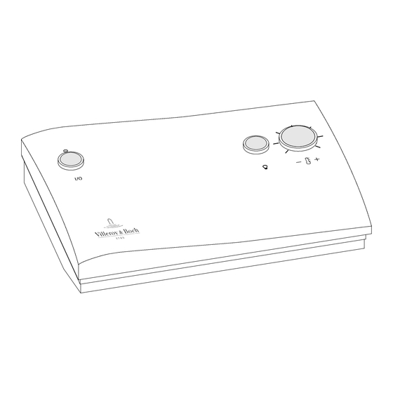
Gegenstände auf oder beim Saunaofen liegen. BRANDGEFAHR! Technische Daten Easy Control Easy Control: 1/ N/ PE 230 V, 50-60 Hz, max. 3 kW Abmessungen: B = 210 mm, H = 150 mm, T = 55 mm Raumbedingungen: Temperatur 0 ºC - 40 ºC, Luftfeuchtigkeit max. 80 % r.F. -
Seite 6: Lieferumfang Easy Control
Easy Control Lieferumfang Easy Control Im Lieferumfang sind folgende Komponenten A, B enthalten: A 1 Stück Temperatursensor Temp B 1 Stück Temperatursensor Temp/STB C 1 Stück Easy Control D 1 Beutel Befestigungsteile - Technische Dokumentation. SEITE 6 50701116/10.05... -
Seite 7: Steuerung Montieren
Easy Control Steuerung montieren 5.1. Steuergehäuse montieren/anschließen Steuergehäuse öffnen An den vier abgebildeten Stellen mit einem Schraubendreher nacheinander die Nasen vorsichtig eindrücken und dabei drehen. Sind alle vier Verriegelungen gelöst, lässt sich das Frontteil abnehmen. 50 mm 190 mm OK FFB = Oberkante fertiger Fußboden... -
Seite 8: Leistungsteil Anschließen
Easy Control Steuerung montieren 5.1. Steuergehäuse montieren/anschließen Gehäuseunterteil montieren/anschließen nicht gesteckt gesteckt Alle Elektroleitungen in der entsprechenden Anschlussreihenfolge von hinten durch das Gehäuseunterteil zusammen mit je einer Kabeltülle einziehen. Gehäuseunterteil mit den vier integrierten Schrauben festschrauben. Steuerung gemäß Anschlussplan anschließen. -
Seite 9: Sensoren Montieren
Easy Control Sensoren montieren 6.1. Montage Temperatursensor Temp/STB Bohrung Ø 10 mm für die Leitungsdurchführung im Kabineninnenraum gemäß dem Installationsplan bohren. Elektroleitung mit einer Kabeltülle verlegen. Elektroleitungen gemäß Anschlussplan anschließen. Siehe Kapitel 7. Elektroleitungen so weit in das Wandelement Sensorplatte Sensorgehäuse... -
Seite 10: Anschluss-/Installationsplan
Easy Control Anschluss-/Installationsplan 7.1. Elektrischer Anschlussplan Easy Control bis 3 kW SEITE 10 50701116/10.05... - Seite 11 Easy Control Anschluss-/Installationsplan 7.1. Elektrischer Anschlussplan Easy Control bis 3 kW SEITE 11 50701116/10.05...
-
Seite 12: Installationsplan Easy Control Bis 3 Kw
Easy Control Anschluss-/Installationsplan 7.2. Installationsplan Easy Control bis 3 kW SEITE 12 50701116/10.05... -
Seite 13: Elektrischer Anschlussplan Easy Control Mit Leistungsteil Bis 9 Kw
Easy Control Anschluss-/Installationsplan 7.3. Elektrischer Anschlussplan Easy Control mit Leistungsteil bis 9 kW SEITE 13 50701116/10.05... - Seite 14 Easy Control Anschluss-/Installationsplan 7.3. Elektrischer Anschlussplan Easy Control mit Leistungsteil bis 9 kW SEITE 14 50701116/10.05...
- Seite 15 Easy Control Anschluss-/Installationsplan 7.3. Elektrischer Anschlussplan Easy Control mit Leistungsteil bis 9 kW SEITE 15 50701116/10.05...
- Seite 16 Easy Control Anschluss-/Installationsplan 7.3. Elektrischer Anschlussplan Easy Control mit Leistungsteil bis 9 kW SEITE 16 50701116/10.05...
-
Seite 17: Installationsplan Easy Control Mit Leistungsteil Bis 9 Kw
Easy Control Anschluss-/Installationsplan 7.4. Installationsplan Easy Control mit Leistungsteil bis 9 kW SEITE 17 50701116/10.05... -
Seite 18: Sollte Etwas Nicht Funktionieren
Sicherung hat ausgelöst. Sicherung wechseln. Steuerung vom Netz trennen. Sicherung (1,25 AT) wechseln oder den Service kontaktieren. Ersatzteile Artikel-Nr. Ersatzteil 3070144 Easy Control 30601112 Leistungsteil 9 kW 50701115 Bedienungsanleitung Easy Control Bedienungsanleitung Easy Control - Export 3060103 STB2 SEITE 18 50701116/10.05... -
Seite 19: Gewährleistung
Easy Control 10. Gewährleistung Villeroy & Boch gewährt Ihnen nach Anschaffung dieses Qualitätsprodukts eine Werksgewährleistung von zwei (2) Jahren. Auf die privat genutzte Saunakabine (ohne elektrische Komponenten wie z.B. Saunaofen und -steuerung, Beleuchtung, Infrarot Heizsystem) gewähren wir eine Gewährleistung von fünf (5) Jahren. -
Seite 20: Informatie • Information
Easy Control 11. Informatie • Information Voor Nederland: Villeroy & Boch Wellness bv Savannahweg 25 • 3542 AW Utrecht • Nederland Tel.: +31 (0) 30 247 34 00 • Fax: +31 (0) 30 247 34 99 E-mail: wellness-nl@villeroy-boch.com • www.villeroy-boch.com Villeroy &... - Seite 21 Assembly/Servicing instructions Easy Control...
- Seite 22 ......7.3. Electrical wiring diagram for Easy Control system with power unit up to 9 kW ..
-
Seite 23: Use For Intended Purpose
FIRE HAZARD! Technical specifications Easy Control system Easy Control system: 230 V, 50-60 Hz, max. 3 kW Dimensions: W = 330 mm, H = 240 mm, D = 90 mm Room conditions: Temperature 0 ºC - 40 ºC, air humidity max. 80 % rel. hum. -
Seite 24: Items Supplied With Easy Control System
Easy Control Items supplied with Easy Control system The following components are supplied: A, B A 1 x Temp temperature sensor B 1 x Temp/STL temperature sensor C 1 x Easy Control system D 1 x bag of fittings - Technical documentation. -
Seite 25: Assemble The Control System
Easy Control Assemble the control system 5.1. Assemble and connect the control system housing Open the control system housing Carefully insert a screwdriver at the four points shown, and use it to push in and turn each lug in sequence. -
Seite 26: Connect The Power Unit
Easy Control Assemble the control system 5.1. Assemble and connect the control system housing Assemble and connect the bottom section of the connected housing connected Thread each wire in from the back, through its own plastic sleeve and via the bottom section of the housing, following the connection order indicated. -
Seite 27: Sensor Installation
Easy Control Sensor installation 6.1. Assembly of Temp/STL temperature sensor Drill a Ø 10 mm hole to allow the cable to he threaded into the cabin in accordance with the installation plan. Fit the power cable in a plastic sleeve. -
Seite 28: Connection/Installation Plan
Easy Control Connection/Installation plan 7.1. Electrical wiring diagram for Easy Control system up to 3 kW PAGE 28 50701116/10.05... - Seite 29 Easy Control Connection/Installation plan 7.1. Electrical wiring diagram for Easy Control system up to 3 kW PAGE 29 50701116/10.05...
-
Seite 30: Installation Plan For Easy Control System Up To 3 Kw
Easy Control Connection/Installation plan 7.2. Installation plan for Easy Control system up to 3 kW PAGE 30 50701116/10.05... -
Seite 31: Electrical Wiring Diagram For Easy Control System With Power Unit Up To 9 Kw
Easy Control Connection/Installation plan 7.3. Electrical wiring diagram for Easy Control system with power unit up to 9 kW PAGE 31 50701116/10.05... - Seite 32 Easy Control Connection/Installation plan 7.3. Electrical wiring diagram for Easy Control system with power unit up to 9 kW PAGE 32 50701116/10.05...
- Seite 33 Easy Control Connection/Installation plan 7.3. Electrical wiring diagram for Easy Control system with power unit up to 9 kW PAGE 33 50701116/10.05...
- Seite 34 Easy Control Connection/Installation plan 7.3. Electrical wiring diagram for Easy Control system with power unit up to 9 kW PAGE 34 50701116/10.05...
-
Seite 35: Installation Plan For Easy Control System With Power Unit Up To 9 Kw
Easy Control Connection/Installation plan 7.4. Installation plan for Easy Control system with power unit up to 9 kW PAGE 35 50701116/10.05... -
Seite 36: Troubleshooting
Replace fuse (1.25 AT) contact customer service. Spare parts Article no. Spare part 3070144 Easy Control system 30601112 Power unit 9 kW 50701115 Operating instructions for Easy Control system Operating instructions for Easy Control system - export version 3060103 STB2 PAGE 36 50701116/10.05... -
Seite 37: Warranty
Easy Control 10. Warranty After your purchase of this quality product Villeroy & Boch provides you with a factory warranty of two (2) years. We provide a warranty of five (5) years for the sauna cabin when used residentially (excluding electrical components such as sauna heater and controls, lighting, infra-red heating system). -
Seite 38: Informatie • Information
Easy Control 11. Informatie • Information Voor Nederland: Villeroy & Boch Wellness bv Savannahweg 25 • 3542 AW Utrecht • Nederland Tel.: +31 (0) 30 247 34 00 • Fax: +31 (0) 30 247 34 99 E-mail: wellness-nl@villeroy-boch.com • www.villeroy-boch.com Villeroy &... - Seite 39 Manuel de montage et de service Easy Control...
- Seite 40 ........7.3. Plan de raccordement électrique Easy Control avec unité d’alimentation jusqu’à 9 kW . . .
-
Seite 41: Utilisation Normale
DANGER DE FEU ! Données techniques Easy Control Easy Control 230 V, 50-60 Hz, max. 3 kW Mesures : L = 330 mm, H = 240 mm, P = 90 mm Conditions de cabine : Température 0 ºC - 40 ºC, Humidité relative maximale de l’air 80 % PAGE 41 50701116/10.05... -
Seite 42: Fourniture Easy Control
Fourniture Easy Control Les composants suivants doivent être fournis : A, B A 1 capteur de température Temp B 1 capteur de température Temp/STB C 1 Easy Control D 1 sachet de pièces de fixation - Documentation technique PAGE 42 50701116/10.05... -
Seite 43: Montage Du Contrôle
Easy Control Montage du contrôle 5.1. Montage/raccordement de la boîte du contrôleur Ouvrir la boîte du contrôleur Poussez les nez aux quatre positions illustrées avec un tournevis et tournez. Quand tous les quatre verrous sont détachés, la partie frontale peut être enlevée. -
Seite 44: Raccordement De L'alimentation
Easy Control Montage du contrôle 5.1. Montage/raccordement de la boîte du contrôleur Montage/raccordement de la partie inférieure de la pas mit boîte Tout les conduits électriques doivent être conduits dans la suite indiquée par derrière à travers la partie inférieure de la boîte. -
Seite 45: Montage Des Capteurs
Easy Control Montage des capteurs 6.1. Montage capteur de température Temp/STB Percer un trou de Ø 10 mm pour les câbles d’alimentation vers l’intérieur de la cabine, suivant le plan d’installation. Mettez un manchon support de câble sur les conduits électriques. -
Seite 46: Plan De Raccordement Et D'installation
Easy Control Plan de raccordement et d’installation 7.1. Plan de raccordement électrique Easy Control jusqu’à 3 kW PAGE 46 50701116/10.05... - Seite 47 Easy Control Plan de raccordement et d’installation 7.1. Plan de raccordement électrique Easy Control jusqu’à 3 kW PAGE 47 50701116/10.05...
-
Seite 48: Plan D'installation Easy Control Jusqu'à 3 Kw
Easy Control Plan de raccordement et d’installation 7.2. Plan d’installation Easy Control jusqu’à 3 kW PAGE 48 50701116/10.05... -
Seite 49: Plan De Raccordement Électrique Easy Control Avec Unité D'alimentation Jusqu'à 9 Kw
Easy Control Plan de raccordement et d’installation 7.3. Plan de raccordement électrique Easy Control avec unité d’alimentation jusqu’à 9 kW PAGE 49 50701116/10.05... - Seite 50 Easy Control Plan de raccordement et d’installation 7.3. Plan de raccordement électrique Easy Control avec unité d’alimentation jusqu’à 9 kW PAGE 50 50701116/10.05...
- Seite 51 Easy Control Plan de raccordement et d’installation 7.3. Plan de raccordement électrique Easy Control avec unité d’alimentation jusqu’à 9 kW PAGE 51 50701116/10.05...
- Seite 52 Easy Control Plan de raccordement et d’installation 7.3. Plan de raccordement électrique Easy Control avec unité d’alimentation jusqu’à 9 kW PAGE 52 50701116/10.05...
-
Seite 53: Plan D'installation Easy Control Avec Unité D'alimentation Jusqu'à 9 Kw
Easy Control Plan de raccordement et d’installation 7.4. Plan d’installation Easy Control avec unité d’alimentation jusqu’à 9 kW PAGE 53 50701116/10.05... -
Seite 54: Si Quelque Chose Ne Fonctionne Pas
Remplacez le fusible (1,25 AT) ou contactez le service clientèle. Pièce de rechange N° d’article Pièce de rechange 3070144 Easy Control 30601112 Alimentation 9 kW 50701115 Manuel d’utilisation Easy Control Manuel d’utilisation Easy Control - Export 3060103 STB2 PAGE 54 50701116/10.05... -
Seite 55: Garantie
Easy Control 10. Garantie Villeroy & Boch vous offre une garantie d’usine de deux (2) ans sur ce produit de qualité, à compter de sa date d’achat. Cette garantie s’étend à cinq (5) ans pour les cabines sauna à usage privé (hors composants électriques tels que la chaufferie et la commande du sauna, l’éclairage et le système de chauffage infrarouge). -
Seite 56: Informatie • Information
Easy Control 11. Informatie • Information Voor Nederland: Villeroy & Boch Wellness bv Savannahweg 25 • 3542 AW Utrecht • Nederland Tel.: +31 (0) 30 247 34 00 • Fax: +31 (0) 30 247 34 99 E-mail: wellness-nl@villeroy-boch.com • www.villeroy-boch.com Villeroy &... - Seite 57 Montage-/Servicerichtlijnen Easy Control...
- Seite 58 ........7.3. Elektriciteitsaansluitingsoverzicht Easy Control met vermogensonderdeel tot 9 kW ..
-
Seite 59: Gebruik Volgens De Richtlijnen
BRANDGEVAAR! Technische gegevens Easy Control Easy Control: 230 V, 50-60 Hz, max. 3 kW Afmetingen: B = 330 mm, H = 240 mm, D = 90 mm Vereisten ruimte: Temperatuur 0 ºC - 40 ºC, luchtvochtigheid max. 80 % relatieve luchtvochtigheid PAGINA 59 50701116/10.05... -
Seite 60: Levering Easy Control
Easy Control Levering Easy Control Bij de levering worden de volgende componenten A, B meegeleverd: A 1 stuks Temperatuursensor Temp B 1 Stück Temperatursensor Temp/STB C 1 stuks Easy Control D 1 zak Bevestigingsonderdelen - Technische documentatie. PAGINA 60 50701116/10.05... -
Seite 61: Besturing Monteren
Easy Control Besturing monteren 5.1. Besturingsbehuizing monteren/aansluiten Besturingsbehuizing openen Op de vier afgebeelde plaatsen met een schroevendraaier één voor één de neuzen voorzichtig indrukken en daarbij draaien. Als alle vier vergrendelingen zijn ontgrendeld, kan de voorkant worden verwijderd. 50 mm... -
Seite 62: Vermogensonderdeel Aansluiten
Easy Control Besturing monteren 5.1. Besturingsbehuizing monteren/aansluiten Besturingsonderstuk monteren/aansluiten geplugd geplugd niet Alle elektrische leidingen in de desbetreffende aansluitvolgorde van achteren door het behuizingsonderstuk samen met telkens een kabeldoorvoer naar binnen trekken. Behuizingsonderstuk met de vier geïntegreerde schroeven vastmaken. Besturing volgens het aansluitingsoverzicht aansluiten. -
Seite 63: Sensoren Monteren
Easy Control Sensoren monteren 6.1. Montage temperatuursensor Temp/STB Boorgat Ø 10 mm voor de leidingdoorvoer in de binnenruimte van de cabine boren volgens het installatieoverzicht. Elektrische leiding met een kabeldoorvoer aanleggen. Besturing volgens het aansluitingsoverzicht aansluiten. Zie hoofdstuk 7. Elektrische leidingen zover in het wandelement... -
Seite 64: Aansluitings-/Installatieoverzicht
Easy Control Aansluitings-/Installatieoverzicht 7.1. Elektriciteitsaansluitingsoverzicht Easy Control tot 3 kW PAGINA 64 50701116/10.05... - Seite 65 Easy Control Aansluitings-/Installatieoverzicht 7.1. Elektriciteitsaansluitingsoverzicht Easy Control tot 3 kW PAGINA 65 50701116/10.05...
-
Seite 66: Installatieoverzicht Easy Control Tot 3 Kw
Easy Control Aansluitings-/Installatieoverzicht 7.2. Installatieoverzicht Easy Control tot 3 kW PAGINA 66 50701116/10.05... -
Seite 67: Elektriciteitsaansluitingsoverzicht Easy Control Met Vermogensonderdeel Tot 9 Kw
Easy Control Aansluitings-/Installatieoverzicht 7.3. Elektriciteitsaansluitingsoverzicht Easy Control met vermogensonderdeel tot 9 kW PAGINA 67 50701116/10.05... - Seite 68 Easy Control Aansluitings-/Installatieoverzicht 7.3. Elektriciteitsaansluitingsoverzicht Easy Control met vermogensonderdeel tot 9 kW PAGINA 68 50701116/10.05...
- Seite 69 Easy Control Aansluitings-/Installatieoverzicht 7.3. Elektriciteitsaansluitingsoverzicht Easy Control met vermogensonderdeel tot 9 kW PAGINA 69 50701116/10.05...
- Seite 70 Easy Control Aansluitings-/Installatieoverzicht 7.3. Elektriciteitsaansluitingsoverzicht Easy Control met vermogensonderdeel tot 9 kW PAGINA 70 50701116/10.05...
-
Seite 71: Installatieoverzicht Easy Control Met Vermogensonderdeel Tot 9 Kw
Easy Control Aansluitings-/Installatieoverzicht 7.4. Installatieoverzicht Easy Control met vermogensonderdeel tot 9 kW PAGINA 71 50701116/10.05... -
Seite 72: Indien Er Iets Niet Functioneert
Zekering verwisselen. Besturing van het elektriciteitsnet afkoppelen. Zekering (1,25 AT) verwisselen of contact opnemen met het servicepunt. Vervangingsonderdelen Artikel-Nr. Vervangingsonderdeel 3070144 Easy Control 30601112 Vermogensonderdeel 9 kW 50701115 Bedieningshandleiding Easy Control Bedieningshandleiding Easy Control - Export 3060103 STB2 PAGINA 72 50701116/10.05... -
Seite 73: Garantie
Easy Control 10. Garantie Villeroy & Boch geeft u een garantie van twee (2) jaar op de aankoop van dit kwaliteitsproduct. Op de voor privé-doeleinden gebruikte saunacabine (zonder elektrische componenten zoals bijv. saunakachel en -bediening, verlichting, infrarood verwarmingssysteem) geven wij een garantie van vijf (5) jaar. -
Seite 74: Notities
Easy Control 11. Notities PAGINA 74 50701116/10.05... - Seite 75 Easy Control 11. Notities PAGINA 75 50701116/10.05...
-
Seite 76: Informatie • Information
Easy Control 12. Informatie • Information Voor Nederland: Villeroy & Boch Wellness bv Savannahweg 25 • 3542 AW Utrecht • Nederland Tel.: +31 (0) 30 247 34 00 • Fax: +31 (0) 30 247 34 99 E-mail: wellness-nl@villeroy-boch.com • www.villeroy-boch.com Villeroy &...