Inhaltsverzeichnis
Werbung
Verfügbare Sprachen
Verfügbare Sprachen
Quicklinks
HiFi
Zusätzlich erforderliche Unterlagen für den Komplettservice
Additionally required Service Documents for the Complete Service
Service
Manual
Sicherheit
Safety
Materialnr./Part No.
72010 800 0000
Materialnummer/Part Number 72010 760 7500
Änderungen vorbehalten/Subject to alteration • Printed in Germany
E-BS 36 0500 • 8002/8012, 8005/8015, 8006/8016
http://www.grundig.com
Service Manual
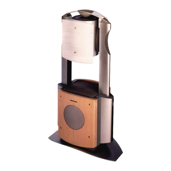
Apollo 2000
G.NK 0150
Grundig Service
Technik:
TV
TV
SAT
VCR/LiveCam
HiFi/Audio
Car Audio
Telekommunikation
Fax:
Planatron
(8.00-22.00 Uhr)
Ersatzteil-Verkauf:
Telefon:
Fax:
Hotline Deutschland...
...Mo.-Fr. 8.00-18.00 Uhr
0180/52318-41
0180/52318-49
0180/52318-48
0180/52318-42
0180/52318-43
0180/52318-44
0180/52318-45
0180/52318-51
0180/52318-99
...Mo.-Fr. 8.00-19.00 Uhr
0180/52318-40
0180/52318-50
Werbung
Inhaltsverzeichnis

Inhaltszusammenfassung für Grundig Apollo 2000
- Seite 1 Service Manual HiFi Apollo 2000 G.NK 0150 Grundig Service Hotline Deutschland..Mo.-Fr. 8.00-18.00 Uhr Technik: 0180/52318-41 0180/52318-49 Zusätzlich erforderliche Unterlagen für den Komplettservice 0180/52318-48 Additionally required Service Documents for the Complete Service VCR/LiveCam 0180/52318-42 HiFi/Audio 0180/52318-43 Service Car Audio 0180/52318-44...
-
Seite 2: Inhaltsverzeichnis
General Section Messgeräte / Messmittel Test Equipment / Aids Beachten Sie bitte das GRUNDIG Messtechnik-Programm, das Sie unter Please note the Grundig Catalog "Test and Measuring Equipment" obtain- folgender Adresse erhalten: able from: GRUNDIG Instruments Test- und Messsysteme GmbH Würzburger Str. 150, D 90766 Fürth/Bay Tel. -
Seite 3: Ausbauhinweise
Apollo 2000 Allgemeiner Teil / General Section Ausbauhinweise Disassembly Instructions Leitungsverlegung Wiring Bevor Sie die Leitungen und insbesondere die Masseleitungen lösen, Before disconnecting any leads and especially the earth connecting muss die Leitungsverlegung zu den einzelnen Baugruppen beachtet leads observe the way they are routed to the individual assemblies. - Seite 4 Allgemeiner Teil / General Section Apollo 2000 3.1 Verstärker-Platten 3.1 Amplifier Boards Je 2 Schrauben (Fig. 4), 4 Schrauben (Fig. 5) und 2 Undo 2 screws (Fig. 4), 4 screws (Fig. 5) and 2 screws Schrauben (Fig. 5) herausschrauben. (Fig. 5) each.
-
Seite 5: Aufstellenundsicherheit
Apollo 2000 Allgemeiner Teil / General Section Bedienhinweise Dieses Kapitel enthält Auszüge aus der Bedienungsanleitung. Weitergehende Informationen entnehmen Sie bitte der gerätespezifischen Bedienungsanleitung, deren Materialnummer Sie in der entsprechenden Ersatzteilliste finden. AUFSTELLEN UND SICHERHEIT ____________________ Damit diese hochwertigen und komfortablen Lautsprecher Ihnen lange Zeit Freu- °C... -
Seite 6: Auf Einen Blick
Allgemeiner Teil / General Section Apollo 2000 AUF EINEN BLICK _____________________________________________________ Die Bedienelemente und Anschlüsse POWER Schaltet den Lautsprecher ein und wieder aus. Der Lautsprecher ist vollständig vom Netz getrennt. Anzeigen Im Netzschalter: rot: Lautsprecher in Bereitschaft (Stand-by); grün: Lautsprecher in Betrieb;... -
Seite 7: Operating Hints
Apollo 2000 Allgemeiner Teil / General Section Operating Hints This chapter contains excerpts from the operating instructions. For further particulars please refer to the appropriate user instructions the part number of which is indicated in the relevant spare parts list. -
Seite 8: Connection And Operation
Allgemeiner Teil / General Section Apollo 2000 OVERVIEW ________________________________________________________________________ Controls and connections POWER Switches the loudspeaker on and off again. The loudspeaker is completely disconnected from the mains. Indicators In the mains button: Red: the loudspeaker is in Stand-by mode;... -
Seite 9: Circuit Diagrams And Layout Of Pcbs
Apollo 2000 Schaltpläne und Druckplattenabbildungen / Circuit Diagrams and Layout of PCBs Apollo 2000 Schaltpläne und Druckplattenabbildungen / Circuit Diagrams and Layout of PCBs Schaltpläne und Druckplattenabbildungen / Circuit Diagrams and Layout of PCBs Verdrahtungsplan / Wiring Diagram SI302 SI301... -
Seite 10: Power Amplifier Board
Schaltpläne und Druckplattenabbildungen / Circuit Diagrams and Layout of PCBs Apollo 2000 Schaltpläne und Druckplattenabbildungen / Circuit Diagrams and Layout of PCBs Apollo 2000 Control-Platte / Control Board D291 R394 R393 T391 D310 IC315 C311 C309 T431 T432 D311 D303... - Seite 11 Apollo 2000 Schaltpläne und Druckplattenabbildungen / Circuit Diagrams and Layout of PCBs Apollo 2000 Schaltpläne und Druckplattenabbildungen / Circuit Diagrams and Layout of PCBs NF-Verstärker-Platte / Power Amplifier Board +30V OPTION-A 22V~ HEAT SI01 FROM 0.1U/50V/10% T4A-L POWER SI02 TRANSFORMER...
- Seite 12 Schaltpläne und Druckplattenabbildungen / Circuit Diagrams and Layout of PCBs Apollo 2000 Schaltpläne und Druckplattenabbildungen / Circuit Diagrams and Layout of PCBs Apollo 2000 Control-Platte / Control Board 220k 220k LOW LEVEL DETECTION R407 R410 C349 4.7K C407 C410 C409...
- Seite 13 Apollo 2000 Schaltpläne und Druckplattenabbildungen / Circuit Diagrams and Layout of PCBs WAKEUP TRX-ON 6.8k R481 6.8k P12/SCLK P11/TxD R482 P13/SDATA P10/RxD BC848B BC848B T492 T495 P20/CNTR0 R471 -DET P20/AN0 6.8k AT-PROT P21/AN1 T493 MITER RX-ON BC848B P22/AN2 T491 T494...
-
Seite 14: Power Supply
Schaltpläne und Druckplattenabbildungen / Circuit Diagrams and Layout of PCBs Apollo 2000 Netzteil / Power Supply 22V~ 22V~ +12V STDBY 22V~ 22V~ 3.3n/20%/400V G2R-1/12VDC SI01 T2.5A-L 14V~ MAINS 14V~ 230V AC 3.3n/20%/400V PTR2 50-60Hz NETZ PTR1 NETZANSCHLUSSPLATTE POWER TRANSFORMER MAINS CON BOARD 29.09.99... - Seite 15 Apollo 2000 Explosionszeichnung und Ersatzteilliste / Exploded View and Spare Parts List Explosionszeichnung und Ersatzteilliste / Exploded View and Spare Parts List GRUNDIG Service 3 - 1...
-
Seite 16: Ersatzteilliste Spare Parts List
84529 671 0400 ELKO AMMO5 1000UF 16V T 00029 83032 415 4600 TRANS.BC 546 B GEG.AMMO-P 5 / 2000 APOLLO 2000 T 00302 83010 048 4800 SMD TRANS BC848B/ BC847B D 00001 83092 154 0100 DIODE 1 N 5401 G GI/FAG G...


