Herunterladen Diese Seite drucken

Werbung

Verfügbare Sprachen

Verfügbare Sprachen

Montageanleitung
Installation instructions
Notice de montage
AS-i Modul
AS-i module
Module AS-i
ProcessLine
AC2910

Werbung

loading

Inhaltszusammenfassung für ifm ProcessLine AC2910

  • Seite 1 Montageanleitung Installation instructions Notice de montage AS-i Modul AS-i module Module AS-i ProcessLine AC2910...
  • Seite 2 
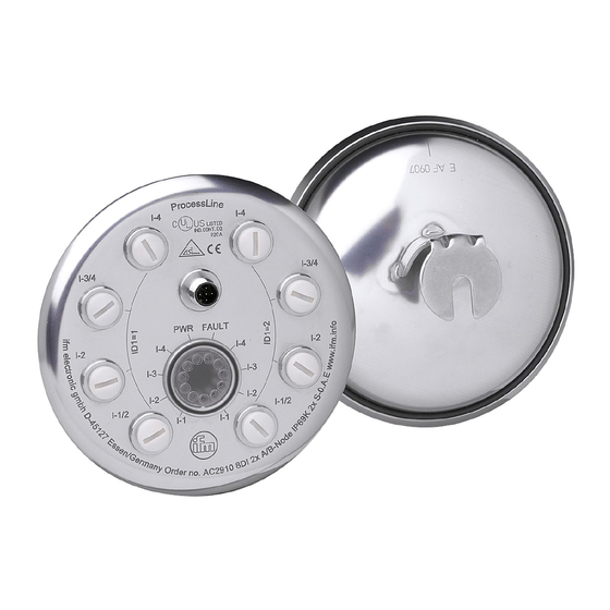
Bestimmungsgemäße Verwendung • AS-i-Profil 2 x S-0.A.E • maximale Anzahl von Modulen pro Master: 31 (2 unabhängige A/B- Slaves pro Modul) • AS-Interface Version 2.1 Bedien- und Anzeigeelemente Elektrischer Anschluss Entfernen Sie die montierten Verschlusskappen (E70297) erst dann, wenn Sie die Anschlussstecker der Sensoren mit den M12-Buchsen verbinden.
  • Seite 3 Eingänge AS-i 1: AS-i + 3: AS-i - 5: FE M12-Buchse Sensorversorgung L+ Sensorversorgung L- Funktionserde Datenbit Eingang Buchse I-1/2 I-1/2 I-2 I-3/4 I-3/4 I-4 Hinweis Das Modul verhält sich im AS-i Netz wie zwei unabhängige A/B- Slaves. Adressieren Die Auslieferungsadresse für beide Slaves ist 0. Adressieren mit dem Adressiergerät AC1154 Das Modul kann mit einem 2/4adrigem Verbindungskabel über den M12-Stecker (AS-i) adressiert werden.
  • Seite 4 • LED FAULT rot blinkt: Peripheriefehler, z. B. Sensorversorgung überlastet bzw. kurzgeschlossen Überlast und Kurzschluss der Eingangsversorgung werden dem AS-i Master (Version 2.1 oder höher) als Peripheriefehler signalisiert. Technische Daten Sie können das Datenblatt bei Bedarf unter der Internetadresse www.ifm.com herunterladen.
  • Seite 5 Function and features • AS-i profile 2 x S-0.A.E • maximum number modules master: (2 independent A/B slaves per module) • AS-Interface version 2.1 Operating and indicating elements Electrical connection Do not remove the mounted protective caps (E70297) before the sen- sor plugs are connected to the M12 sockets.
  • Seite 6 AS-i Inputs 1: AS-i + 3: AS-i - 5: FE M12 socket sensor supply L+ sensor supply L- functional earth Data bit input socket I-1/2 I-1/2 I-2 I-3/4 I-3/4 I-4 Note In the AS-i network the module functions as two independent A/B slaves. Addressing The address for the two slaves is set to 0 at the factory.
  • Seite 7 Overload and short circuit of the input supply are signalled as peri- pheral fault to the AS-i master (version 2.1 or higher). Technical data You can download the data sheet from the Internet if required (www.ifm.com).
  • Seite 8 Fonctionnement et caractéristiques • profil 2 x S-0.A.E • nombre maximal de modules par maître: 31 (2 esclaves A/B indépen- dants par module) • version AS-interface 2.1 Eléments de service et d'indication Raccordement électrique N'enlever les capuchons protecteurs utilisés (E70297) que lorsque les connecteurs des capteurs sont raccordés aux prises M12.
  • Seite 9 AS-i entrées 1: AS-i + 3: AS-i - 5: FE prise M12 broche alimentation capteur L+ alimentation capteur L- terre fonctionnelle Bit de données entrée prise I-1/2 I-1/2 I-2 I-3/4 I-3/4 I-4 broche Remarque Dans le réseau AS-i le module fonctionne comme deux esclaves A/B indépendants.
  • Seite 10 Une surcharge ou un court-circuit de l'alimentation des entrées est sig- nalé au maître AS-i (version 2.1 ou supérieure) en tant que défaut péri- phérie. Données techniques Vous pouvez télécharger la fiche technique à l'adresse internet www.ifm.com si besoin.
  • Seite 11 Limited voltage The device shall be supplied from an isolating transformer having a secondary Listed fuse rated as noted in the following table. Overcurrent protection Control-circuit wire size Maximum protective device rating ampere (0.13) (0.20) (0.32) (0.52) (0.82) (1.3)