Emerson EXM Bedienungsanleitung
Verfügbare Sprachen
Verfügbare Sprachen
Quicklinks
G e n e r a l i n f o r m a t i o n :
EXM/EXL are unipolar stepper motor driven
electronic expansion valves for precise control of
refrigerant mass flow in refrigeration systems.
!
S a f e t y i n s t r u c t i o n s :
• Read operating instructions thoroughly. Failure to
comply can result in device failure, system damage
or personal injury
• According to EN 13313 it is intended for use by
persons having the appropriate knowledge and
skill.
• In a severely contaminated system, avoid
breathing acid vapors and avoid contact with skin
from contaminated refrigerant / lubricants.
Failure to do so could result in injury.
• Before opening any system make sure pressure in
system is brought to and remains at atmospheric
pressure.
• Do not exceed the specified maximum ratings for
pressure, temperature, voltage and current.
• Ensure that the system piping is grounded.
• Do
not
release
any
refrigerant
atmosphere!
• Do not use any other fluid media without prior
approval of EMERSON. Use of fluid not listed
could result in a change of hazard category of
product and consequently change of conformity
assessment
requirement
accordance with European pressure equipment
directive 14/68/EU.
• Do not operate valve connected directly to supply
voltage. Use suitable stepper motor driver.
• Before installation or service disconnect all
voltages from system and device.
• Do not operate system before all cable connections
are completed.
• Observe and avoid mechanical damage of
component housing.
• Ensure that design, installation and operation are
according
to
European
standards/regulations.
M o u n t i n g l o c a t i o n :
• Choice of mounting location: If the coil is exposed
to moisture/water (regardless of temperature), the
metal parts of coil may begin to rust over time.
• The valve must be installed with head upside or
within ± 90° from upside as per Fig.1a.
• Recommendation for use in refrigeration applications
(self-contained display cabinet/unit): Valve to be
installed vertical with coil upside or between vertical
and maximum angle of 60° from vertical if the valve
is located in cold/wet compartment. (Fig.1b)
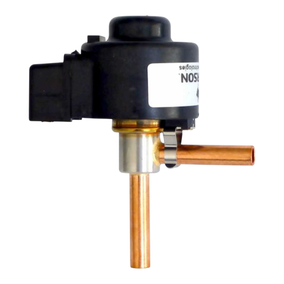
T e c h n i c a l D a t a :
Type
Maximum working pressure at TS: –30°C...+70°C
Connection, DN
Fluid group
Refrigerant
Dimensions
Protection class:
Nominal Supply Voltage U
Maximum Current I
max
Marking
Independent VDE test for heat pumps and display
cases with R290 / R32
Emerson Climate Technologies GmbH
Am Borsigturm 31 I 13507 Berlin I Germany
Electronic Expansion Valves EXM/EXL
• For best results locate the valve as close as possible
to the distributor or inlet of evaporator.
I n s t a l l a t i o n :
• The valve has Bi-flow performance capability.
• Protect the orifice of valve against entering particle
by means of installing filter or filter drier at the inlet
of valve or on liquid line.
• All valves are delivered at full open. Do not charge
system before closure of valve.
• Check
subcooling and make sure no flash gas is present
at the inlet of valve before attempting to check
valve operation. Install an EMERSON sight glass
AMI or MIA before the valve.
B r a z i n g : ( F i g . 2 )
• Perform and consider the brazing joint as per
EN 14324.
• Before and after brazing clean tubing and brazing
joints.
• Remove the coil by pulling it from valve prior to
brazing.
• Do not exceed the max. body temperature of 120°C!
into
the
• Minimize vibrations in the piping lines by
appropriate solutions.
• To avoid oxidization, it is advised to purge the
system with an inert gas such as nitrogen while
brazing.
P r e s s u r e t e s t :
for
product
in
After completion of installation, a test pressure must
be carried out as follows:
‾ According to EN378 for systems which must
comply with European pressure equipment
directive 14/68/EU.
‾ To maximum working pressure of system for other
applications
!
Warning:
• Failure to do so could result in loss of refrigerant
and personal injury.
• The pressure test must be conducted by skilled
and
national
persons with due respect regarding the danger
related to pressure.
T i g h t n e s s T e s t :
Conduct a tightness test according to EN 378-2 with
appropriate equipment and method to identify leakages
of external joints. The allowable leakage rate must be
according system manufacturer's specification.
www.climate.emerson.com/en-gb
Operating instruction
for
sufficient
refrigerant
EXM
PS: 45 bar
1/4" ODM
I & II
R290, R32, R 410A, R 407C, R 134a
see Fig. 4
IP65 excluded JST (IP30) terminal (see Fig.5)
12 VDC ±10% for EXM-125
24 VDC ±10% for EXM-24U
260 mA for EXM-125
130 mA for EXM-24U
not applicable
Additional requirements at the end of this operation instructions must be considered
Date: 22.03.2019
E l e c t r i c a l c o n n e c t i o n :
!
Warning:
• Entire electrical connections have to comply with
local regulations.
• Improper wiring will result wrong direction of
rotation or no rotation of stepper motor.
Wiring and mounting of coil:
• Prewired coil with cable length of approximately
1 meter is ready for connection to the electronic
charge/
board.
Wiring to driver/controller:
• See the wiring diagram of used driver or controller.
E X M / E X L - 1 2 5
White
Winding ½
Orange
E X M / E X L - 2 4 U
White
Winding ½
Red
(common)
Orange
Fig. 3
O p e r a t i o n :
• See operating instructions of used electronic
driver/controller.
• If the power to the valve is interrupted, the valve will
keep as the position it was before power off.
S e r v i c e / M a i n t e n a n c e :
• Before shutting the power off, drive the valve to fully
close position.
• Defective EXM/EXL must be replaced, they cannot
be repaired.
• For motor check, use an ohmmeter with suitable
range.
• Internal resistance between each winding is 46 Ω for
EXM/EXL-125 and 185 Ω for EXM/EXL-24U.
(windings see Fig. 3).
PS: 45 bar
1/4" ODF / 8 mm ODM
R290, R32, R 410A, R 407C, R 134a
12 VDC ±10% for EXL-125
24 VDC ±10% for EXL-24U
260 mA for EXL-125
130 mA for EXL-24U
not applicable
EXML_OI_ML_R07_865021.docx
Yellow
Blue Brown
Winding ¾ (common)
Yellow
Blue
Winding ¾
EXL
I & II
see Fig. 4

Verwandte Anleitungen für Emerson EXM


Inhaltszusammenfassung für Emerson EXM
-
Seite 2: Betrieb
• Kältemittel nicht in die Atmosphäre entweichen • Vor und nach dem Löten sind die Lötstellen zu lassen! reinigen. Wicklung ½ • Es dürfen nur von EMERSON freigegebene • Vor dem Einlöten ist die Spule abzunehmen. Medien eingesetzt werden. Die Verwendung nicht • Max. Gehäusetemperatur 120°C... - Seite 9 Geltungsbereich: Emerson EXM/L Expansionsventile sind für den Einsatz in einem fertigen Produkt oder in einem Kühlsystem integriert und werden elektrisch über eine separate Steuerung mit Gleichstromversorgung gesteuert. Das Ventil ist für den Einbau in ein Gerät / System ausgelegt. Um mit jedem Regler einsetzbar zu sein, ist dieser nicht in die Prüfung einbezogen.