ABB UMC100.3 Montageanweisung
Vorschau ausblenden
Andere Handbücher für UMC100.3:
- Montageanweisung (2 Seiten) ,
- Technische beschreibung (158 Seiten)
Quicklinks
en Installation instructions
UMC100.3
de Montageanweisung
1SAJ530000Rx2xx
es Instrucciones de montaje
fr Notice de montage
it
Istruzioni di montaggio
sv Installation och skötsel
PTB 10 ATEX 3016
pl Instrukcja montażu
no Monteringsveiledning
cs Pokyny pro instalaci
cn 安装说明书
ru Инструкция по монтажу
ABB STOTZ-KONTAKT GmbH
Eppelheimer Str. 82
Postfach 10 1680
69123 Heidelberg
69006 Heidelberg
Germany
Germany
Telephone +49 (0 ) 6221 701-0
Telefax
+49 (0 ) 6221 701-240
E-mail
automation-helpline.desto@de.abb.com
Internet
http://www.abb.de/stotz-kontakt
en
Please refer to the manual for safety instructions.
System description
de
Die Sicherheitshinweise entnehmen Sie bitte dem Handbuch.
Systembeschreibung
es
Por favor, tomar las advertencias de seguridad del manual.
Descripción del sistema
fr
Vous trouverez les consignes de sécurité dans le manuel.
Description du système
it
Fate riferimento alle indicazioni di sicurezza che sono
contenute nel seguente manuale.
Descrizione del sistema
sv Läs säkerhetsanvisningarna i manualen.
Systembeskrivning
pl
Prosimy zapoznać się z instrukcjami bezpieczeństwa
z podręcznika użytkownika.
Opis układu
no
Vennligst se manualen for sikkerhetsanvisninger.
Systembeskrivelse
cs Konzultujte prosím příručku ohledně bezpečnostních pokynů.
Popis systému
cn 相关安全说明请参照使用手册
系统描述
ru
Инструкции по безопасности приведены в руководстве.
Описание системы
Internet
:
en
http://new.abb.com/low-voltage/products/motor-controllers
OTechnical descriptions
2CDC135033D02xx.PDF (Eng)
de
http://new.abb.com/low-voltage/de/produkte/motor-controller
OTechnische Beschreibung
2CDC135033D01xx.PDF (Deut.)
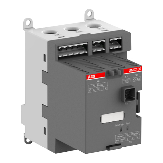
en
Connection
de
Anschluss
es
en
Current path for feeding through wires up to a diameter of 11 mm
a
de
Strompfad zum Durchstecken von Drähten bis 11 mm Durchmesser
es
Circuito de corriente para paso de cables de hasta 11 mm de diámetro
fr
Trajet du courant pour traversée de fils jusqu'à un diamètre de 11 mm
it
Circuito di corrente per infilare fili di diametro fino a 11 mm
sv
Kabelgenomföring för kablar upp till 11 mm diameter
cn
用于插入直径最大至11 mm电线的电流通路
ru
Канал трансформатора тока для проводов диаметром до 11 мм
en
Connection PTC (T1,T2)
en
Connection I/O module
d
e
de
Anschluss PTC (T1,T2)
de
Anschluss E/A-Modul
es
Conexión PTC (T1,T2)
es
Conexión para módulo E/S
fr
Connexion PTC (T1,T2)
fr
Connexion module E/S
Connessione PTC (T1,T2)
Collegamento modulo I/O
it
it
sv
Anslutning PTC (T1,T2)
sv
Anslutning I/O-modul
cn
PTC接口(T1,T2)
cn 输入/输出模块接口
ru
Подключение термодатчика PTC (T1, T2)
ru
Подключение модуля В/В
UMC100.3 DC
10
en
24 V DC, GND Supply voltage
de
24 V DC, GND Versorgungsspannung
es
24 V DC, GND Tensión de alimentación
fr
24 V DC, GND tension d'alimentation
it Tensione di alimentazione 24 V DC, terra
sv
24 V DC, GND Manöverspänning
cn
24 V DC, GND
电源电压
ru
24 В пост. т. , GND (земля) напряжение питания
en Screw-type terminal
de Schraubtechnik
M2.5 / 0.098 in
es Técnica de conexión
0.5 Nm / 4.5 in.lb
por tornillo
fr
Bornes à vis
0.2 ... 2.5 mm 2
it
Terminale a vite
28 ... 12 AWG
sv Skruvanslutning
pl Złącze śrubowe
no Skruklemme
0.2 ... 2.5 mm 2
cs Svorka se šroubem
28 ... 12 AWG
cn 螺钉端子
ru Винтовая клемма
en Connection cable
pl Kabel połączeniowy
de Verbindungskabel
no Tilkoblingskabel
es Cable conector
cs Připojovací kabel
fr
Câble de connexion
cn 连接电缆
it
Cavo di collegamento
ru Соединительный кабель
sv Anslutningskabel
UMC100 - I/O Module UMCIO-CAB.30
Distance max. 3.0 m
30cm
1SAJ691000R0001
I/O Module - I/O Module IOIO-CAB.30
30cm
1SAJ692000R0001
II (2) G [Ex e] [Ex d] [Ex px]
II (2) D [Ex t] [Ex p]
en Safety and Commissioning Notes for Motors in EEx Areas
The UMC100 is a 1-channel device providing internal self-tests which guarantees relia-
UMC100.3
1SAJ530000Rx2xx
ble motor protection on a high level. A suitable housing for the UMC is required when
II (2) G [Ex e] [Ex d] [Ex px]
using the UMC in Ex areas.
II (2) D [Ex t] [Ex p]
The UMC100 must not be connected to frequency converters, softstarters or similar
PTB 10 ATEX 3016
components in Ex applications.
English
2CDC 135 033 D02xx
The UMC100 is approved for device group II, category 2 zones „G" or „D" (i.e., explosive
German
2CDC 135 033 D01xx
atmospheres caused by gases, vapors, mists or air, or by combustible dust).
The UMC100 was developed and designed according to the standards
Englisch
2CDC 135 033 D02xx
IEC 61508 and ISO13849.
Deutsch
2CDC 135 033 D01xx
The increased risks in EEx areas require, amongst other things, careful observation
of the following notes and standards:
Inglés
2CDC 135 033 D02xx
•
IEC 60079-7: Electrical apparatus for explosive atmospheres: Equipment protection
Alemán
2CDC 135 033 D01xx
by increased safety "e"
Anglais
2CDC 135 033 D02xx
•
IEC 60079-14: Electrical apparatus for explosive atmospheres: Electrical installa-
Allemand
2CDC 135 033 D01xx
tions design, selection and erection
•
IEC 60079-17: Electrical apparatus for explosive atmospheres: Electrical installa-
tions inspection and maintenance
Inglese
2CDC 135 033 D02xx
Tedesco
2CDC 135 033 D01xx
Safe state
For the reverse starter control function, the safe state is present if the relays DO0
Engelsk
2CDC 135 033 D02xx
and DO1 are de-energized (open). For all other motor operation modes (e. g. DOL,
Tysk
2CDC 135 033 D01xx
Star-Delta Start), the safe state is present if relay DO0 is de-energized (open).
Safety functions
The following functions of the UMC100 are safety-relevant:
Angielski
2CDC 135 033 D02xx
Niemiecki
2CDC 135 033 D01xx
Thermal overload protection: The thermal overload protection function induces the
de-energization of the relay(s) if the device detects a thermal overload situation
(calculated using the thermal model) or a phase loss.
Engelsk
2CDC 135 033 D02xx
Tysk
2CDC 135 033 D01xx
Thermistor motor protection: This safety function brings the system to the safe state
if the resistance measured at the PTC inputs (T1/T2) exceeds the limit specified in
the corresponding standard. This safety function only has to be activated if the motor
Angličtina
2CDC 135 033 D02xx
Němčina
2CDC 135 033 D01xx
provides a corresponding sensor.
Configuring the safety functions
2CDC 135 033 D02xx
英文版使用手册
A) Thermal overload protection
2CDC 135 033 D01xx
德文版使用手册
The following parameters have to be set for proper function of the thermal overload
protection.
Английский язык 2CDC 135 033 D02xx
Немецкий язык
2CDC 135 033 D01xx
Nominal motor current I
require the approval of the PTB or a comparable institution.
en
xx = sequential version number
For motors it is furthermore necessary to observe the ratio between the tripping
xx = fortlaufende Versionsnummer
de
current and the nominal current (I
es
xx = Número de versión secuencial
fr
xx = N° de version séquentiel
can be found in the certificate or on the motor type plate. The tripping time must be
it
xx = Numero di versione sequenziale
shorter than the heating period t
sv
xx = Löpande versionsnummer
motor must run below the coordinate given by I
pl
xx = numer kolejny wersji
pole-changing starter control function.
no
xx = fortløpende versjonsnummer
cs
xx = posloupné číslo verze
Trip class (parameter 28): The tripping time must be shorter than the heating period t
xx = 版本序列号
cn
Current factor (parameter 31) – for external current transformer: The transmission
ru
xx = последовательный номер версии
ratio of the used transformer must be set correctly.
Phase loss protection (parameter 42): The phase loss protection function is activated
ex works. Deactivation of this function is only permitted for demonstration purposes.
Resistive load must be set to „NO" (Parameter 26).
Set correct number of phases (parameter 47).
Conexión
fr
Connexion
it
Connessione
en
Mounting by 4 screws M4. Eyelets can be broken off for DIN rail mounting
b
de
Befestigung mit 4 M4 Schrauben, Ösen bei Hutprofil-Montage abbrechbar
es
Sujeción con 4 tornillos M4. Para montaje en perfil DIN, romper las pestañas de sujeción con tornillos.
fr
Fixation à l'aide de 4 vis M4. Montage oméga : rompre les œillets
it
Fissaggio tramite 4 viti M4; se il montaggio avviene su barra DIN, si possono staccare gli occhielli
sv
Infästning med 4 M4 skruvar, öra kan brytas av vid DIN-skenemontage.
cn
用4个M4螺钉固定。DIN导轨安装时可将安装孔折断。
ru
Крепление 4 винтами М4, при монтаже на профиль лепестки можно отломать.
en
Connection for the Control Panel
f
de
Anschluss für Bediengerät
es
Conexión para el panel de control
fr
Connexion pour l'unité de commande
it
Collegamento del pannello di comando
sv
Anslutning för kontrollpanelen
cn 控制面板接口
ru
Разъем для панели управления
UMC100.3 UC
j
en 24V DC, GND for supply of I/O modules
de 24 V DC, GND für Versorgung der E/A-Module
es 24V DC, GND para alimentación de módulos de E/S
fr
24 V DC, GND pour l'alimentation des modules E/S
it
24 V DC, terra, per l'alimentazione dei moduli I/O
sv 24V DC, GND för strömförsörjning av I/O-moduler
cn 24V DC, GND 用于I/O模块电源
ru 24 В пост. т. , GND (земля) для питания Вх./Вых.
модулей
en Dimensions
de Abmessungen
fr
Dimensions
it
Dimensioni
pl Wymiary
no Dimmensjoner
cn 尺寸
ru Размеры
106.7
4.201"
100
3.937"
Ø 4.5 Ø 0.18"
X6
DO Relay
C
C
0 1 2
0 V
24 V DC
0 V
j
24 V DC
Distance max. 3.0 m
Out
j
L1
NC
L3
24 V
NC
L2
NC
0 V
VI150
Out
N
k
24 V
L
RDY
0 V
Diag
ERR
N
DOC
DO0
NC
L
0V
24V DC
NC
en
Warning!
Installation and maintenance have to be per-
formed according to the technical rules, codes
and relevant standards, e.g. EN 60204 part 1, by
skilled electricians only.
de
Warnung!
Die Installation und Wartungsarbeiten dieses
Gerätes müssen durch eine Elektrofachkraft
durchgeführt werden, nach den anerkannten
technischen Regeln, Vorschriften und relevanten
Normen, z. B. EN 60204 Teil 1.
pl
Ostrzeżenie!
UMC100.3
Czynności instalacyjne i konserwacyjne mogą być
wykonywane zgodnie z zasadami technicznymi,
przepisami prawa i odnośnymi normami,
np. EN 60204 część 1, wyłącznie przez
wykwalifikowanych elektryków.
cn
警告!
该产品的安装和维护只能由专业技术人员根据技术
规程、规定和相关的标准,
比如 EN60204的第一部分,进行操作。
, I
(parameter 29/30): Motors intended for use in Ex areas
e1
e2
/I
) and the heating period t
. These information
a
e
E
, i. e., the tripping characteristic curve for the cold
E
/I
and t
. I
must be set only for the
a
e
E
e2
pl
Podłączenie
no
Tilkobling
en
Output relay (Common root and contactors)
c
Important: Screws of unused terminals have to be screwed in to achieve protection against accidental contact.
de
Ausgangsrelais (Relaiskontakte und gemeinsamer Wurzelkontakt)
Wichtig: Schrauben von nicht benutzten Klemmen müssen zum Berührungsschutz angezogen werden.
es
Salida de relé (contactos de relé con contacto de raíz común)
Importante: Los tornillos de bornes no utilizados deberán apretarse para protegerlos de contactos accidentales.
fr
Relais de sortie (contacteurs et contact racine commun)
Important : Les vis des bornes de connexion non utilisées doivent être serrées pour que soit assurée une protection contre les contacts accidentels.
it
Relè d'uscita (contatti a relè e contatto comune)
Importante: Stringere anche le viti dei morsetti non utilizzati, per impedire un eventuale contatto
sv
Utgångsrelä (reläkontakter med gemensam punkt)
en
Connector Communication Interface
g
Viktigt: Skruvarna på oanvända klämmor måste dras åt för att ett skydd mot beröring skall uppnås.
de
Anschluss Kommunikationsinterface
cn
输出继电器(同公共点继电器触点)
重要:未使用的端子的螺钉也必须拧紧,以防意外接触。
es
Conector Interfaz de comunicación
ru
Выходные реле (релейные контакты с общим основным контактом)
fr
Connecteur interface de communication
Важно: винты неиспользуемых клемм необходимо затянуть, чтобы предотвратить случайное прикосновение.
it
Collegamento per connettore bus di campo
h
sv
Anslutning Kommunikationsgränssnitt
cn
通信接口插头
ru
Соединитель интерфейса связи
k UMC100.3 UC
en
110-240 V AC/DC Supply voltage
de
110-240 V AC/DC Versorgungsspannung
es
110-240 V AC/DC Tensión de alimentación
fr
110-240 V AC/DC Tension d'alimentation
it
Tensione di alimentazione 110-240 V AC/DC
sv
110-230V AC/DC Manöverspänning
cn
110-240 V AC/DC 电源电压
ru
110-240 В перем. т./пост. т. напряжение питания
d
e
Thermistor
I/O Module
24 V DC
Inputs
Interface
es Dimensiones
T1 T2
Ca Cb
sv Dimensioner
DO3
cs Rozměry
f
max.
250 mA
UMC100-PAN
Communication
Interface
Power
X5
g
70
2.76"
j
0 V
24 V DC
X7
X8
T1 T2
Ca Cb
X9
Trip/Rdy
Run
Power
DO
DI 24V
d
e
0V 24V
3
0 ... 5
X5
Thermistor
I/O Module
24 V DC
57 2.24"
Inputs
Interface
T1 T2
Ca Cb
f
UMC100.3 DC
DO3
max.
UMC100-PAN
50 mA
UMC100.3 DC
I
Communication
Interface
g
X10
X5
UMC100.3 UC
k
j
UMC100.3 UC
110-240 V AC/DC
es
¡Advertencia!
La instalación y mantenimiento de estos aparatos
debe efectuarla un especialista, de acuerdo a las
reglas, instrucciones y normas relevantes,
p.ej.: EN60204, Parte 1.
it
Avvertenze!
L'installazione e la manutenzione
devono essere realizzate in accordo con le
normative tecniche vigenti (esempio: EN60204-
1) solamente da personale specializzato.
no
Advarsel!
Montering og vedlikehold må kun utføres av
faglærte elektrikere i henhold til tekniske regler,
lover og relevante standarder,
f.eks. EN 60204 del 1.
ru
Внимание!
Монтаж и обслуживание должны выполняться только
квалифицированными электриками, в соответствии с
техническими правилами, нормами и соответсвующими
стандартами, например EN 60204 часть 1.
B) Thermistor motor protection
To activate the thermistor motor protection function it is necessary to change parameter 9 ‚PTC'
to „Tripping". The input is then automatically monitored for short-circuit and wire break
conditions. In case of a fault, a motor switch-off is initiated.
C) Signaling
Malfunction of the relay output or the main contactor is signaled as check back fault
according to ISO 13849. Signaling may be performed via the fieldbus or an fault output
(signaling relay or 24 V transistor output). The fault output is configured as sum fault
output by default. To activate the fault output set parameter „Fault output (27)" according
to the application's purpose.
D) Other parameters
Check back (parameter 22) is set to ‚current' ex works and must not be changed.
Automatic reset of thermal overload faults. Parameter 14 ‚automatic reset' is set to ‚off'
ex works and must not be changed.
This has no effects to the configurable error acknowledgement of external errors
(on the multifunctional inputs or the DX1xx I/O module).
Test position: The multifunctional inputs (parameters 114/115/116) can be used to activate
the test position. After commissioning, the test position must not be activated unintentionally
during regular operation. This is usually avoided by the design of the switchgear
(e. g. mechanical test position).
Emergency start: Parameter 15 ‚emergency start' is set to ‚off' ex works and must not be
changed. According to IEC 60079-14/11.3, a phase imbalance detection function has to
be configured for the protection of delta-connected motors during underload operation.
Checking the configuration
The correct parameter configuration can be checked as follows:
• On the LCD operating panel
• Using the Device Type Manager (DTM): The parameters can be read from the device
via DTM and then checked for correct configuration. This can be performed on site or
via the bus.
Protecting the parameters against unintentional changes
Once the parameter configuration is finished, it is necessary to enable the parameter
locking function in order to avoid unintentional changing of parameters.
The state of the parameter locking function is indicated by the padlock symbol on the
LCD operating panel.
Maintenance and repair
The devices do not require any service. Repair work may only be performed by the
manufacturer.
Tests
The device automatically performs periodic self-tests. Therefore, no retesting has to be
performed by the user if the motor is switched at least 1 time per year.
Otherwise, a test start of the motor must be performed to test the correct function of the
relay.
Characteristic values according to IEC 61508 and ISO 13849 - See UMC100 handbook.
.
E
„Safety and Commissioning Notes for Motors in EEx Areas"
cs
Připojení
sv
Anslutning
cn
en
2 system LEDs
LEDs h
Trip/Rdy
de
2 System-LEDs
en
Trip/Ready
es
2 LEDs de sistema
de
Auslösung/Bereit
fr
2 LED système
Disparo/ Listo
es
it
2 LEDs di sistema
fr
Déclenchement/ Prêt
sv
2 system-LED
it
Apertura/ Pronto
2个系统LED指示灯
cn
sv
Utlösning/ Redo
ru
2 системных СИД
cn
脱扣/ 就绪
ru
Расцепление/ Готов
L1, L2, L3
c
F1
Contactor
Supply
(e.g. 230 V AC)
Relay Outputs
DOC DO0
DO1
DO2
3
I
UMC100.3 DC
Lim
DI0
DI1
DI2
DI3
DI4 DI5
a
UMC100.3 DC
3
i
M
L1, L2, L3
c
F1
Contactor
Supply
(e.g. 230 V AC)
Relay Outputs
DOC DO0
DO1
DO2
3
UMC100.3 UC
Lim
DI0
DI1
DI2
DI3
DI4 DI5
a
IO-Modules
i
3
M
fr
Avertissement!
L'installation et la maintenance de cet appareil
doivent être réalisées par des personnes
compétentes et connaissant les textes et direc-
tives règlementaires, ainsi que les normes de
référence telle que la norme EN60204.1.
sv
Varning!
Installation och underhåll av denna apparat
får endast utföras av behörig person, och
enligt gällande föreskrifter och standarder
t.ex. EN 60204 del 1.
cs
Varování!
Instalace a údržba musí být prováděna v
souladu s technickými zásadami, předpisy a
příslušnými normami, např. EN 60204 část 1,
jen kvalifikovanými elektrikáři.
Translation for de, es, fr, it, pl, no, cs, sv ->>
ru
Подключение
连接
Run
Motor running
Motor läuft
Motor en marcha
Moteur tourne
Motore in funzione
Motor till
马达运行
Двигатель работает
L1
L2
L3
1
2
3
4
5
X6
X7
X8
DO Relay
T1 T2
Ca Cb
C
C
0 1 2
6
L1
L2
L3
7
X9
1
2
Trip/Rdy
Run
8
3
4
5
Power
DO
DI 24V
0V 24V
3
0 ... 5
X5
9
X6
X7
X8
DO Relay
T1 T2
Ca Cb
C
C
0 1 2
6
10
7
X9
Trip/Rdy
Run
8
UMC100.3 UC
Power
Out
DO
DI 24V
N L
0V 24V
3
0 ... 5
X10
X5
9
11
10

Verwandte Anleitungen für ABB UMC100.3


Inhaltszusammenfassung für ABB UMC100.3
- Seite 1 Disparo/ Listo Motor en marcha 2 LEDs di sistema Déclenchement/ Prêt Moteur tourne UMC100.3 UC k UMC100.3 UC UMC100.3 DC 2 system-LED Apertura/ Pronto Motore in funzione 24 V DC, GND Supply voltage en 24V DC, GND for supply of I/O modules 110-240 V AC/DC Supply voltage 2个系统LED指示灯...
- Seite 2 Sicherheits- und Inbetriebnahmehinweise für Motoren im EEx-Bereich Notas de seguridad y de puesta en marcha para motores en zonas EEx Notes relatives à la sécurité et à la mise en service des moteurs dans les zones EEx Istruzioni di sicurezza e di messa in esercizio per motori in zone EEx Il dispositivo UMC100 è...