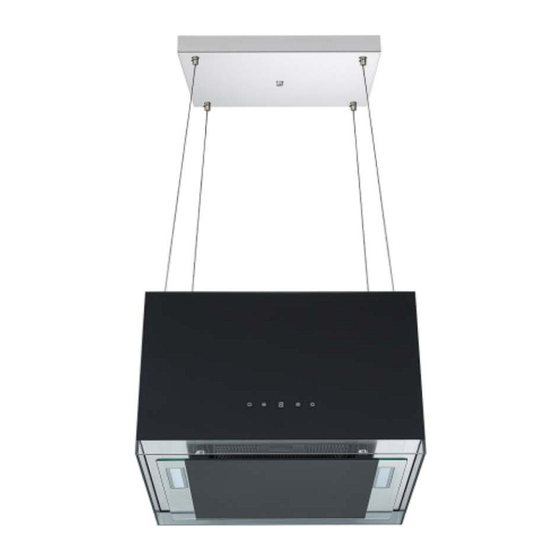
Respekta CH 11050 IS Bedienungs- & Installationsanleitung
Vorschau ausblenden
Andere Handbücher für CH 11050 IS:
- Bedienungs- & installationsanleitung (40 Seiten)
Werbung
Verfügbare Sprachen
Verfügbare Sprachen
Werbung
Inhaltsverzeichnis

Inhaltszusammenfassung für Respekta CH 11050 IS
- Seite 1 Mod. No.: Bedienungs- & Installationsanleitung Dunstabzugshaube User manual & Installation Instruction Cooker hoods CH 11050 IS CH 11050 IW SY-132D2IW-E4r-C46-L22-500 NEG-Novex Großhandelsgesellschaft für Elektro- und Haustechnik GmbH, Chenover Str. 5, D-67117 Limburgerhof...
-
Seite 13: Fernbedienung
Berühren Sie zum Löschen der Codierung 5 Sekunden lang die Power Taste E. Die Tastenbeleuchtungen beginnen von einer Taste zur anderen zu blinken. Die Haube befindet sich im Verbindungsmodus. Berühren Sie dann erneut die Power-Taste E für 5 Sekunden. Der vorherige Verbindungscode wird gelöscht Wenn die vorherige Codierung gelöscht wurde, kehrt die Dunstabzugshaube in den Standby- Modus zurück. -
Seite 15: Zubehörliste
ZUBEHÖRLISTE Inselhauben CH 11050 ISB CH 11050 ISW Name Abbildung Anzahl Aktiv Kohlefilter Decken Montageplatte Montageplatte Abdeckung Drahtseil Beton Dübel Exzenterschraube φ6*60mm zur Befestigung der Montageplatte ohne Dübel an einer Betondecke. Senkschrauben ST6 x 40 mm ( 4 Stück zur Montage der Montageplatte mit Dübeln an einer Betondecke / 8 Stück zur Montage an einer Holzdecke) Senkkopfschrauben ST4 ×... - Seite 16 Deutsch 18. Montageanleitung Dunstabzugshauben Modelle: CH 11050 ISB CH 11050 IWB Sicherheitsabstand zwischen Kochfeld und Haube beachten. (Kapitel 11.1) in der Bedienungsanleitung. Die Decke muss ein Gewicht von mindestens 120 kg tragen und die Dicke der Decke muss ≥ 30 mm betragen.
- Seite 17 Für die Montage der Dunstabzugshaube an einer Betondecke gehen Sie wie folgt vor: 1. Verwenden Sie die beiliegende Bohrschablone und markieren Sie die 4 Bohrlöcher für die Montageplatte (B) mit einem Bleistift an der Decke. 2. Bohren Sie die 4 benötigten Löcher (6mm / 60mm tief) in die Decke.
- Seite 18 6. Führen Sie die 4 Drahtseil durch die Löcher in der Montageplatten-Abdeckung und das Gerätekabel durch das Loch 2. Dann führen Sie das Gerätekabel durch die Aussparung in der Montageplate. (Abb. B4) Ab jetzt ist die Gegenwart von 2-3 Personen erforderlich. Eine bis zwei davon Abb.
- Seite 19 11. Schieben Sie die Schraubenaufnahmezylinder Montageplatte-Abdecking Höhenverstell- über die Montageplatte und schraube fixieren Sie sie mit der Fixierschraube (Abb. B6) Drahtseil 12. Falls nötig, Länge der Fixirmutter Abb. B6 Drahtseile allenfalls mittels der verstellbaren Schrauben justieren, damit der Hauben Körper waagrecht zu hängen kommt.
- Seite 20 Dann befolgen Sie nachfolgende Montageschritte: 1. Verwenden Sie die beiliegende Bohrschablone und markieren Sie die 8 Bohrlöcher für die Montageplatte (B) mit einem Bleistift an der Holzdecke. 2. Stechen Sie die Punkte für die 8 Schrauben (B) mit einer Aale leicht an. 3.
-
Seite 32: Remote Control
When the previous code has been cleared, the cooker hood turns back to standby mode, touch the power key E on the cooker hood for 5 seconds. The key illuminations starts to flash from one key to the othe. The cooker hood is in connection mode, then, tocu any key on remote control to confirm the connection. -
Seite 34: Accessory List
ACCESSORY LIST Island Cooker hoods CH 11050 ISB CH 11050 ISW Name Picture Charcoal filter Mounting plate Decorative plate Wire rope Wall plug (for mounting the mounting plate on a concrete ceiling) Eccentric screw φ6*60mm for mounting the mounting plate without wall plugs on a concrete ceiling. -
Seite 35: Installation Instruction
English 18. Installation Instruction Modells: CH 11050 ISB CH 11050 IWB Observe the safety distance between the hob and hood. (Chapter 11.1 in the user's manual) The ceiling must can bear at least 120KGs weight, and the thickness of the ceiling must be ≥30MM. - Seite 36 To install the extractor hood on a concrete ceiling, proceed as follows: 1. Use the enclosed drilling template and mark the 4 drill holes for the mounting plate (B) with a pencil on the ceiling 2. Drill the 4 required holes (6mm / 60mm deep) in the ceiling.
- Seite 37 6. Guide the 4 wire cables through the holes in the suspension plate cover, the device cable through hole mount the supplied connector on the device cable. Then run the device cable through the recess in the mounting plate. (Fig .B4) From now on, the presence of 2-3 people is required.
- Seite 38 11. Slide the mounting plate cover over the mounting plate and fix it with the fixing screw (Fig B6) 12. If necessary, adjust the length of the wire ropes using the adjustable screws, so that the hood body hangs horizontally. 13.
- Seite 39 1. 1. Use the enclosed drilling template and mark the 8 drill holes for the mounting plate (B) with a pencil on the suspended ceiling. 2. Lightly pierce the points for the 8 screws (B) with an eel. 3. Then follow the installation steps 4. to 13. in the above section "Mounting the extractor hood on a concrete ceiling"...


