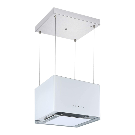
Respekta CH 11050 ISB Montageanleitung
Insel dunstabzugshauben
Vorschau ausblenden
Andere Handbücher für CH 11050 ISB:
- Bedienungs- & installationsanleitung (29 Seiten) ,
- Bedienungs- & installationsanleitung (40 Seiten)

Verwandte Anleitungen für Respekta CH 11050 ISB


Inhaltszusammenfassung für Respekta CH 11050 ISB
- Seite 1 Mod. No.: Montageanleitung Insel Dunstabzugshauben Installation Instruction Island Cooker hoods CH 11050 ISB CH 11050 IWB SY-132D2IW-E4r-C59-L52-500 NEG-Novex Großhandelsgesellschaft für Elektro- und Haustechnik GmbH, Chenover Str. 5, D-67117 Limburgerhof...
-
Seite 2: Zubehörliste
ZUBEHÖRLISTE Inselhauben CH 11050 ISB CH 11050 IWB Name Abbildung Anzahl Aktiv Kohlefilter Decken Montageplatte Montageplatte Abdeckung Drahtseil Beton Dübel Exzenterschraube sφ6 x 60mm Senkkopfschrauben ST6 x 40 (4 davon für Montage der Montageplatte an einer Beton Decke / 8 für Montage an einer Holzdecke) Senkkopfschrauben ST4 ×... -
Seite 3: Elektrische Installation
Deutsch Montageanleitung Dunstabzugshauben Modelle: CH 11050 ISB CH 11050 IWB Sicherheitsabstand zwischen Kochfeld und Haube beachten. (Kapitel 11.1) in der Bedienungsanleitung. Die Decke muss ein Gewicht von mindestens 120 kg tragen und die Dicke der Decke muss ≥ 30 mm betragen. - Seite 4 Für die Montage der Dunstabzugshaube an einer Betondecke gehen Sie wie folgt vor: 1. Verwenden Sie die beiliegende Bohrschablone und markieren Sie die 4 Bohrlöcher für die Montageplatte (B) mit einem Bleistift an der Decke. 2. Bohren Sie die 4 benötigten Löcher (10mm / ca. 43mm tief) in die Decke.
- Seite 5 6. Führen Sie die 4 Drahtseil durch die Löcher in der Montageplatten-Abdeckung und das Gerätekabel durch das Loch 2. Dann führen Sie das Gerätekabel durch die Aussparung in der Montageplate. (Abb. B4) Ab jetzt ist die Gegenwart von 2-3 Personen erforderlich. Eine bis zwei davon Abb.
- Seite 6 Abb. B6 Montageplatten- Abdeckung 11. Schieben Sie die Montageplatten-Abdecking über die Montageplatte und Verstellbare Schraube fixieren Sie sie mit der Fixierschraube (Abb. B6) Fixierschraube 12. Falls nötig, Länge der Drahtseile allenfalls mittels der verstellbaren Schrauben justieren, damit der Hauben Körper waagrecht zu hängen kommt.
- Seite 7 1. Verwenden Sie die beiliegende Bohrschablone und markieren Sie die 8 Bohrlöcher für die Montageplatte (B) mit einem Bleistift an der Holzdecke. 2. Stechen Sie die Punkte für die 8 Schrauben (B) mit einer Aale leicht an. 3. Befolgen Sie dann die unter obigem Kapitel "Montage der Dunstabzugshaube an einer Betondecke"...