Inhaltsverzeichnis
Werbung
Verfügbare Sprachen
Verfügbare Sprachen
Quicklinks
Betriebsanleitung | Operating instructions | Notice d'instruction
Istruzioni per l'uso | Instrucciones de servicio | Bruksanvisning | 使用手册 | Manual de
instruções
R412028475-BAL-001-AE
2022-12; Replaces: 2022-05
DE/EN/FR/IT/ES/SV/ZH/PT
AVENTICS™ SPRA
Elektrischer Antrieb mit Kolbenstange
Rod-style electrical actuator
Entraînement électrique avec tige de piston
Azionamento elettrico con asta pistone
Accionamiento eléctrico con vástago de émbolo
Elektrisk drivning med kolvstång
带活塞杆的电动驱动装置
Acionamento elétrico com haste de pistão
Werbung
Inhaltsverzeichnis
Fehlerbehebung

Verwandte Anleitungen für Emerson AVENTICS SPRA


Inhaltszusammenfassung für Emerson AVENTICS SPRA
- Seite 1 Betriebsanleitung | Operating instructions | Notice d’instruction Istruzioni per l'uso | Instrucciones de servicio | Bruksanvisning | 使用手册 | Manual de instruções R412028475-BAL-001-AE 2022-12; Replaces: 2022-05 DE/EN/FR/IT/ES/SV/ZH/PT AVENTICS™ SPRA Elektrischer Antrieb mit Kolbenstange Rod-style electrical actuator Entraînement électrique avec tige de piston Azionamento elettrico con asta pistone Accionamiento eléctrico con vástago de émbolo Elektrisk drivning med kolvstång...
-
Seite 2: Inhaltsverzeichnis
Inhaltsverzeichnis Zu dieser Dokumentation ........................................Gültigkeit der Dokumentation ......................................Zusätzliche Dokumentationen ......................................1.2.1 Zusätzliche Dokumentation für Produkt ohne Motor............................1.2.2 Zusätzliche Dokumentation für Produkt mit Motor ............................1.2.3 Zusätzliche Vorschriften..................................... Darstellung von Informationen ......................................1.3.1 Warnhinweise ........................................1.3.2 Symbole..........................................Verwendete Bezeichnungen ......................................Sicherheit ............................................ - Seite 3 6.4.4 Montage des Motoranbausatzes ..................................Montage Parallel-Motoranbausatz (Baugröße 32/40/63 mm) ............................6.5.1 Verwendungszweck ......................................6.5.2 Schrauben und Anzugsmomente M .................................. 6.5.3 Montage der Zwischenplatte....................................6.5.4 Montage des Zahnriemens....................................6.5.5 Montage des Getriebedeckels .................................... Montage (Baugröße 100 mm)......................................6.6.1 Motoranbausatz......................................... 6.6.2 Montage der Kupplung ...................................... 6.6.3 Montage des Inline-Motoranbausatzes................................
-
Seite 4: Zu Dieser Dokumentation
1 Zu dieser Dokumentation Lesen Sie diese Dokumentation vollständig und insbesondere das Kapitel g 2. Si- NOTICE! Seals age faster under aggressive ambient conditions. Defective seals will lead to pneumatic leaks and non-compliance with the degree of protection. cherheit, bevor Sie mit dem Produkt arbeiten. Inspect seals more frequently. -
Seite 5: Nicht Bestimmungsgemäße Verwendung
INFO: Wenn das Produkt in einem anderen Bereich eingesetzt werden soll: 2.6 Gefahrenquellen Einzelgenehmigung beim Hersteller einholen. Hinweise 2.6.1 Verletzungsgefahr • Das Produkt ist eine unvollständige Maschine nach Maschinenrichtlinie Stolpergefahr durch unsachgemäß verlegte Kabel und Leitungen 2006/42/EG. • Kabel und Druckluftleitungen so verlegen, dass niemand darüber stolpern kann. -
Seite 6: Produkt Lagern
• Das Produkt erst unmittelbar vor der Installation aus der Verpackung neh- Produktidentifikation men. Das bestellte Produkt wird anhand der Materialnummer eindeutig identifiziert. • Sicherstellen, dass das Produkt nicht herunterfallen kann, bevor das Produkt Die Materialnummer finden Sie an folgender Stelle: aus den Befestigungen gelöst wird. -
Seite 7: Einbauzubehör
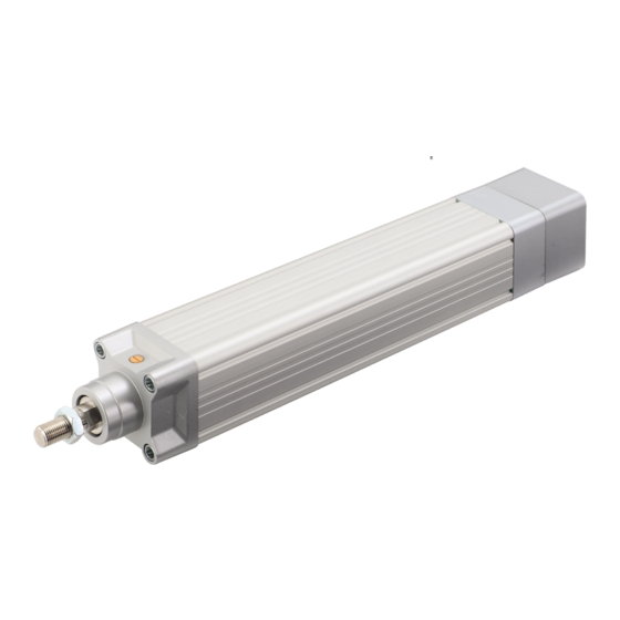
5.4.2 Einbauzubehör 5.5 Produktübersicht (Baugröße 100 mm) Zubehör für elektrischen Antrieb mit Kolbenstange 5.5.1 Antrieb (Baugröße 32/40/63 mm) Elektrischer Antrieb mit Kolbenstange (Baugröße 100 mm) Abb. 3: Zubehör (für Baugröße 32/40/63 mm) Abb. 5: Überblick (Baugröße 100 mm) 1 Lineareinheit 2 Näherungssensor 3 Fußbefestigungssatz axial 4 Mittenschwenkbefestigung 1 Gewinde für Kopfbefestigung 2 Mantelrohr 5 Lagerböcke 6 Schwenkzapfenbefestigung vorne... -
Seite 8: Montage Und Installation
Drehrichtung des Motors beim Ausfahren der Lineareinheit Werkzeug Zubehörteile • Ausschließlich vom Hersteller freigegebenes Zubehör verwenden. Siehe g 14. Zubehör. 6.2 Vorbereitung 6.2.1 Produkt auspacken und prüfen 1. Anhand der Materialnummer prüfen, ob das Produkt mit Ihrer Bestellung übereinstimmt. 2. Produkt auf Transportschäden und Lagerungsschäden prüfen. Ein beschädigtes Produkt darf nicht montiert werden. -
Seite 9: Montage Inline-Motoranbausatz (Baugröße 32/40/63 Mm)
4. Teile der Maschine bzw. Anlage sichern, in die die Lineareinheit eingebaut Tab. 3: Montage Inline-Motoranbausatz: Schrauben und Anzugsmomente M für werden soll. Kupplungsgehäuse und Kupplung 5. Gelenkkopf (2) und Einbauzubehör (1) an der Maschine bzw. Anlage fest- Kupplungsgehäuse (9) Kupplung (12) schrauben. -
Seite 10: Montage Des Motoranbausatzes
Lagemaße für Kupplung mit Fußbefestigung ben (3) festziehen. Sicherstellen, dass die Kupplung je nach Konfiguration (mit/ohne Fußbefesti- gungssatz) entsprechend der Angaben zu den Lagemaßen montiert wird: - Für Kupplung ohne Fußbefestigung. Siehe g Tab. 4. - Für Kupplung mit Fußbefestigung. Siehe g Tab. 5. - Anzugsmomente für Schrauben. -
Seite 11: Montage Des Zahnriemens
1. Motor (2) auf Zwischenplatte (4) montieren: Vierkantdichtung ohne Aus- 6. Zahnriemenscheibe (7) und zweite Spannhülse auf der Motorseite ausrichten. schnitt (3) einsetzen und alle Inbusschrauben (1) anziehen. Siehe folgende Tabelle. Dabei die Ausrichtmarke (5) auf der Zwischenplatte beachten. Tab. 9: Ausrichtung der Zahnriemenscheibe (7) auf der Motorseite 2. -
Seite 12: Montage (Baugröße 100 Mm)
6.6 Montage (Baugröße 100 mm) 6.6.1 Motoranbausatz Der Motoranbausatz ermöglicht den Anbau eines Motors mit axialem Schaft. 6.6.2 Montage der Kupplung Abb. 18: Einbau des Getriebedeckels 18 Dichtscheibe 19 Getriebedeckel 1. Flachdichtung (8) zwischen Getriebedeckel (19) und Zwischenplatte (4) le- gen. 2. Dichtscheiben (18) über die Inbusschrauben (9/10) schieben. Abb. 20: Montage der Kupplung 3. -
Seite 13: Montage Des Parallel-Motoranbausatzes
Tab. 13: Montage des Inline-Motoranbausatzes: Schrauben und Anzugsmomen- te M für Motor und Motoradapter Motor (1) Motoradapter (3) Motoranbausatz Schraube [Nm] Schraube [Nm] R412028547 SPRA-100 / 1FK704x M6×30 M8×30 R412028548 SPRA-100 / 1FK706x M8×30 M8×30 R412028549 SPRA-100 / 1FK708x M10×30 M8×30 R412028550 SPRA-100 / 1FK710x M12×40 M8×30 R412028535 SPRA-100 / IC830M6xx-BK M8×30... -
Seite 14: Montage Der Sensoren
Baugröße Maximale kinetische Energie in J (Joule) 6.7 Montage der Sensoren –3 32 mm Max. 0,1 x 10 J –3 40 mm Max. 0,2 x 10 J –3 63 mm Max. 0,4 x 10 J –3 100 mm Max. 1 x 10 J 8 Betrieb 8.1 Grundlegende Vorgaben Allgemeine Vorgaben •... -
Seite 15: Vorgehen
Einsatz unter aggressiven Umgebungsbedingungen Überprüfung der Dichtungen Aggressive Umgebungsbedingungen sind z. B.: • Hohe Temperaturbelastung • Starker Schmutzanfall • Nähe zu fettlösenden Flüssigkeiten oder Dämpfen Als Folge von aggressiven Umgebungsbedingungen ergeben sich weitere Vorga- ben für die Inspektion: • Prüfintervall für Dichtungen an die Umgebungsbedingungen anpassen. ACHTUNG! Unter aggressiven Umgebungsbedingungen altern Dichtungen schneller. -
Seite 16: Produkt Nachschmieren (Baugröße 100 Mm)
9.5.1 Produkt nachschmieren (Baugröße 100 mm) Motoranbausatz Schraube RS 30×10 * Mrev = Millionen Umdrehungen ** Erste Nachschmierung nach 100.000 Umdrehungen. 9.5.2 Wartungskontrollen Bei jedem Wartungsintervall folgende Überprüfungen durchführen: • Gleitspindel „LS“: Das Axialspiel muss kleiner als die folgenden Werte sein: –... -
Seite 17: Lineareinheit Demontieren
2. Produkt prüfen anhand der nachfolgend beschriebenen Fehlerbilder. 3. Störungsbehebung durchführen mithilfe der Informationen unter „Abhilfe“. Hinweise zu Zubehör finden Sie auf der Produktseite im Emerson Store. Wenn sich die Störung nicht wie beschrieben beheben lässt: Produkt demon- tieren und zurücksenden. Siehe g 4.3 Produkt... - Seite 18 Contents About this documentation......................................... Documentation validity ........................................Additional documentation ........................................ 1.2.1 Additional documentation for product without motor ............................1.2.2 Additional documentation for product with motor............................. 1.2.3 Additional regulations ......................................Presentation of information ......................................1.3.1 Warnings..........................................1.3.2 Symbols ..........................................Designations used..........................................Safety ..............................................
- Seite 19 6.4.4 Assembling the motor attachment kit................................Assembling the parallel motor attachment kit (sizes 32/40/63 mm) ..........................6.5.1 Purpose..........................................6.5.2 Screws and tightening torques M ..................................6.5.3 Assembling the intermediate plate ..................................6.5.4 Assembling the toothed belt ....................................6.5.5 Assembling the gearbox cover ................................... Assembly (size 100 mm) ........................................
-
Seite 20: About This Documentation
Meaning of the signal words 1 About this documentation Signal word Meaning Read this documentation completely, especially chapter g 2. Safety before work- ing with the product. Danger Immediate danger to the life and health of persons. These instructions contain important information on the safe and appropriate as- Failure to observe these notices will result in serious health consequences, including death. -
Seite 21: Obligations Of The Operator
2.6.2 Material damage 2.4 Obligations of the operator Damage due to too high mechanical loads 2.4.1 Identifications and warning signs on the product The product can be damaged by too high mechanical loads. As owner, ensure that identifications and warning signs on the product are clearly •... -
Seite 22: Returning The Product
• Keep the product in its packaging until the time of installation. 5.4 Product overview (sizes 32/40/63 mm) • If the product is stored for more than 3 months: Check the general condition of all parts monthly. If required: Recondition or renew the protective treat- 5.4.1 Actuator ment. -
Seite 23: Product Overview (Size 100 Mm)
Parallel motor attachment kit (for sizes 32/40/63 mm) 5.5.2 Installation accessories Accessories for rod-style electrical actuator (size 100 mm) Fig. 4: Parallel motor attachment kit (for sizes 32/40/63 mm) 1 Intermediate plate 2 Gearbox cover Fig. 6: Accessories (for size 100 mm) 3 Clevis mounting 1 Linear unit 2 Proximity sensor 3 Foot mounting 4 Trunnion (pair) 5.5 Product overview (size 100 mm) -
Seite 24: Required Accessories, Materials And Tools
• Make sure that the product is not damaged by falling parts or incorrect tool NOTICE! If no input torque is applied, the push rod can be moved by hand or usage. The push rod and seals in particular must not be damaged. If neces- by gravity. - Seite 25 6.4.2 Screws and tightening torques M Positioning dimensions for coupling without foot mounting Fig. 10: Inline motor attachment kit: screw position Fig. 12: Positioning dimensions for coupling without foot mounting Table 2: Assembling the inline motor attachment kit: screws and tightening Table 4: Positioning dimensions for coupling without foot mounting torques M for motor adapter and motor Motor attachment kit...
-
Seite 26: Screws And Tightening Torques M
6.4.4 Assembling the motor attachment kit Motor (1) Intermediate plate (12) Motor attachment kit Screw [Nm] Screw [Nm] R412028525 SPRA-32 / IC830M2xx-Kx M5×16 M6×16 R412028527 SPRA-40 / IC830M2xx-Cx M5×16 M6×16 R412028529 SPRA-63 / IC830M4xx-Gx M6×20 M8×25 Table 7: Assembling the parallel motor attachment kit: screws and tightening torques M for gearbox covers (9) and (10) Gearbox cover (9) -
Seite 27: Assembling The Gearbox Cover
Motor attachment kit Pulley [Nm] R412028525 SPRA-32 / IC830M2xx-Kx GT3-5M-Z22 R412028527 SPRA-40 / IC830M2xx-Cx GT3-5M-Z22 R412028529 SPRA-63 / IC830M4xx-Gx GT3-5M-Z44 8. Insert the pretensioning screw (13) into the side hole of the intermediate plate (4) and tighten the toothed belt (6) with the pretensioning screw until both guides are straight and parallel. -
Seite 28: Assembly (Size 100 Mm)
Optional mounting element 2. Push the coupling hub onto the motor shaft and align the coupling hole with the end of the motor shaft. 3. Tighten the screws (13). Tightening torques: - For inline motor attachment kit. See g Table 14. - For parallel motor attachment kit. See g Table 16. 6.6.3 Assembling the inline motor attachment kit Fig. 21: Assembling the inline motor attachment kit 1 Screw... -
Seite 29: Assembling The Parallel Motor Attachment Kit
2. Mount the inline gearbox (9) to the linear unit (7): Insert the seal (6) between Motor (9) Coupling (13) the two components and tighten the housing with 4 screws (5). Motor attachment kit Screw [Nm] Screw [Nm] 3. Place the seal (4) on the inline gearbox (9), then attach the motor adapter R412028548 SPRA-100 / 1FK706x M8×30... -
Seite 30: Notes On Safety
Interval Maintenance work To be carried Details 7.2 Notes on safety out by To eliminate risks during commissioning, observe the notes on safety. See Clean linear unit. Instructed per- See section g 2. Safety. g 9.4.2 Procedure Monthly Check tight fit of the push rod and Qualified per- 7.3 Preparation add-on parts, correct if necessary. -
Seite 31: Cleaning
• Check housing (1) for cracks and gaps. 9.5 Maintenance • Check profile (2) for cracks, gaps and damage. Notes • Check push rod (3) for scratches and indents. • Observe the maintenance plan for the overall system: Further maintenance Detailed inspection tasks may result from the maintenance plan for the overall system and the maintenance intervals specified therein. -
Seite 32: Maintenance Checks
3. Protect the system against being restarted (accident prevention). Motor attachment 4. Allow the product and adjacent system parts to cool down (accident preven- SPRA-RN-100 Relubrication Nominal stroke: 2 mm tion). position From mechanical 5 mm 5. Wear protective clothing (accident prevention). end stop: Relubrication interval Every 20 Mrev* or 200 km... -
Seite 33: Technical Data
Defective motor, gearbox or Replace product (qualified person). screw nut 13 Technical data This section contains an excerpt of the most important technical data. Further technical data can be found on the product page in the Emerson store. General Specifications Size 32 mm 40 mm... - Seite 34 Sommaire A propos de cette documentation...................................... Validité de la documentation ......................................Documentation supplémentaire ....................................... 1.2.1 Documentation supplémentaire pour le produit sans moteur ..........................1.2.2 Documentation supplémentaire pour le produit avec moteur..........................1.2.3 Prescriptions supplémentaires ................................... Présentation d’informations ......................................1.3.1 Avertissements ........................................1.3.2 Symboles ...........................................
- Seite 35 6.4.4 Montage du kit de montage de moteur................................Montage du kit de montage de moteur parallèle (pour tailles 32/40/63 mm) ........................6.5.1 Utilisation prévue ....................................... 6.5.2 Vis et couples de serrage M ....................................6.5.3 Montage de la plaque intermédiaire................................... 6.5.4 Montage de la courroie dentée................................... 6.5.5 Montage du couvercle de réducteur...................................
-
Seite 36: Propos De Cette Documentation
1 A propos de cette documentation Lire entièrement la présente documentation et en particulier le chapitre g 2. Sé- NOTICE! Seals age faster under aggressive ambient conditions. Defective seals will lead to pneumatic leaks and non-compliance with the degree of protection. curité avant de travailler avec le produit. -
Seite 37: Utilisation Non Conforme
Remarques 2.6 Sources de danger • Le produit est une machine incomplète selon la directive machines 2006/42/ 2.6.1 Risque de blessure Risque de trébuchement dû à des câbles et conduites mal posés 2.3 Utilisation non conforme • Poser les câbles et les conduites d’air comprimé de manière à éviter tout Il y a mauvaise utilisation prévisible lorsque la machine incomplète est utilisée à... -
Seite 38: Transport Et Stockage
4 Transport et stockage 4.1 Transport du produit Dangers pendant le transport • Lors du déchargement et du transport du produit emballé jusqu’à sa destina- tion, procéder avec prudence et respecter les informations figurant sur l’em- ballage. • Déballer le produit juste avant de procéder à son installation. •... -
Seite 39: Accessoires De Montage
5.4.2 Accessoires de montage 5.5 Aperçu du produit (taille 100 mm) Accessoires pour entraînement électrique avec tige de piston 5.5.1 Entraînement (tailles 32/40/63 mm) Entraînement électrique avec tige de piston (taille 100 mm) Fig. 3: Accessoires (pour tailles 32/40/63 mm) Fig. 5: Aperçu (taille 100 mm) 1 Unité linéaire 2 Capteur de proximité... -
Seite 40: Montage Et Installation
Sens de rotation du moteur lorsque l’unité linéaire est déployée Outils Accessoires • Utiliser exclusivement des accessoires autorisés par le fabricant. Voir g 14. Accessoires. 6.2 Préparation 6.2.1 Déballage et vérification du produit 1. A l’aide de la référence, vérifier si le produit correspond à votre commande. 2. -
Seite 41: Accessoires De Montage
4. Fixer les pièces de la machine ou de l’installation dans laquelle l’unité linéaire Tab. 3: Montage du kit de montage de moteur en ligne : vis et couples de serrage doit être installée. pour le boîtier de coupleur et le coupleur 5. -
Seite 42: Montage Du Kit De Montage De Moteur
Dimensions de position pour coupleur avec fixation par patte 3. Monter la bride du moteur (10) sur le boîtier de coupleur (8) : insérer le joint rond (4) entre la bride du moteur et le boîtier de coupleur et fixer par le ser- d’équerre rage des 4 vis (3). -
Seite 43: Montage De La Plaque Intermédiaire
6.5.3 Montage de la plaque intermédiaire Fig. 15: Montage de la plaque intermédiaire 1 Vis à six pans creux 2 Moteur 3 Joint carré sans encoche 4 Plaque intermédiaire 5 Repère d’alignement 6 Courroie dentée 7 Poulie de courroie dentée 8 Joint plat Fig. 17: Poulies de courroie dentée (vue détaillée) 9 Vis 10 Vis... -
Seite 44: Montage Du Couvercle De Réducteur
Tab. 10: Fixation des poulies de courroie dentée : couple de serrage M Elément de fixation en option Kit de montage de mo- Poulie de courroie [Nm] teur dentée R412028537 SPRA-32 / 1FK7015 GT3-3M-Z18 R412028540 SPRA-40 / 1FK7022 GT3-3M-Z24 R412028541 SPRA-40 / 1FK7034 GT3-5M-Z22 R412028544 SPRA-63 / 1FK7034 GT3-5M-Z22 R412028525... -
Seite 45: Montage Du Kit De Montage De Moteur En Ligne
1. Pousser le premier moyeu du coupleur avec les dents au maximum sur la Procédure broche filetée de l’unité linéaire. 1. Fixer le coupleur (8) à l’unité linéaire (7) avec la vis (13). Voir chapitre 2. Pousser le moyeu du coupleur sur l’arbre du moteur et aligner l’alésage du g 6.6.2 Montage du coupleur. -
Seite 46: Détection Des Butées De Fin De Course Mécaniques
Tab. 16: Montage du kit de montage de moteur parallèle : vis et couples de ser- 7 Mise en service rage M pour le moteur et le coupleur Moteur (9) Coupleur (13) 7.1 Spécifications générales Kit de montage de mo- [Nm] [Nm] Spécifications pour le produit teur R412028547... -
Seite 47: Aperçu
9.2 Aperçu Spécifications générales • En cas d’usure accrue, raccourcir les intervalles de maintenance en fonction du degré d’usure. • Si l’unité linéaire est utilisée dans des conditions ambiantes autres que celles spécifiées dans ces instructions, vérifier les composants une fois par mois pour détecter toute altération visible (oxydation, saleté, etc.). -
Seite 48: Procédure
• Pour le nettoyage, utiliser exclusivement de l’eau et, le cas échéant, un pro- Kit de montage de duit de nettoyage doux (protection du matériel). moteur Quantité de lubrifiant 8 cm³ • L’eau utilisée pour le nettoyage (y compris les additifs chimiques) doit avoir un pH neutre. -
Seite 49: Démontage Et Remplacement
Ce chapitre contient un extrait des principales données techniques. D’autres don- • Utiliser exclusivement des pièces de rechange ou des kits de remplacement nées techniques sont disponibles sur la page dédiée au produit dans l’Emerson du catalogue en ligne (prévention des accidents, protection du matériel). -
Seite 50: Accessoires
Max. 95 % (sans condensation) tionnement) Humidité relative (sto- Max. 90 % (sans condensation) ckage) Montage Spécification Position de montage Indifférente 14 Accessoires Des informations relatives aux accessoires sont disponibles sur la page dédiée au produit dans l’Emerson Store. AVENTICS™ SPRA | R412028475-BAL-001-AE | Français... - Seite 51 Indice Sulla presente documentazione......................................Validità della documentazione ......................................Documentazione aggiuntiva ......................................1.2.1 Documentazione aggiuntiva per il prodotto senza motore..........................1.2.2 Documentazione aggiuntiva per il prodotto con motore............................ 1.2.3 Disposizioni aggiuntive ...................................... Presentazione delle informazioni ...................................... 1.3.1 Avvertenze di sicurezza ...................................... 1.3.2 Simboli..........................................
- Seite 52 6.4.4 Montaggio del kit motore ....................................Montaggio del kit motore parallelo (per grandezza 32/40/63 mm) ........................... 6.5.1 Scopo d’uso ........................................6.5.2 Viti e coppie di serraggio M ....................................6.5.3 Montaggio della piastra intermedia..................................6.5.4 Montaggio della cinghia dentata ..................................6.5.5 Montaggio del coperchio del riduttore ................................Montaggio (grandezza 100 mm).......................................
-
Seite 53: Sulla Presente Documentazione
1 Sulla presente documentazione Leggere questa documentazione in ogni sua parte e in particolare il capitolo NOTICE! Seals age faster under aggressive ambient conditions. Defective seals will lead to pneumatic leaks and non-compliance with the degree of protection. g 2. Sicurezzaprima di adoperare il prodotto. Inspect seals more frequently. -
Seite 54: Uso Non A Norma
INFO: Se il prodotto deve essere utilizzato in un altro settore: richiedere l’au- 2.6 Fonti di pericolo torizzazione individuale al produttore. Indicazioni 2.6.1 Pericolo di lesioni • Il prodotto è una quasi-macchina secondo la direttiva 2006/42/CE. Pericolo di inciampare dovuto a cavi e condotte non posati correttamente 2.3 Uso non a norma •... -
Seite 55: Stoccaggio Del Prodotto
• Prima di sganciare il prodotto dai fissaggi, assicurarsi che il prodotto non pos- • Sulla parte posteriore del prodotto. sa cadere. • Sulla targhetta di identificazione. • Attuare misure idonee volte a evitare danneggiamenti durante il sollevamen- to del prodotto. 5.3 Segnali di avvertimento sul prodotto •... -
Seite 56: Panoramica Sul Prodotto (Grandezza 100 Mm)
Kit motore parallelo (per grandezza 32/40/63 mm) 5.5.2 Accessori di montaggio Accessori per azionamento elettrico con asta pistone (grandezza 100 mm) Fig. 4: Kit motore parallelo (per grandezza 32/40/63 mm) 1 Piastra intermedia 2 Coperchio riduttore 3 Fissaggio a forcella Fig. 6: Accessori (per grandezza 100 mm) 1 Unità lineare 2 Sensore di prossimità... -
Seite 57: Pianificazione
6.1 Pianificazione 6.3 Montaggio dell'unità lineare Requisiti 6.1.1 Condizioni di montaggio • Tutte le indicazioni del progetto possono essere realizzate. Disposizioni generali • La preparazione è conclusa. • Assicurarsi che il prodotto, dopo essere stato montato, non sia sottoposto a Indicazioni carichi meccanici. -
Seite 58: Montaggio Del Kit Motore Inline (Grandezza 32/40/63 Mm)
9. Se necessario: applicare sull'unità lineare segnali di divieto e di avvertimento 1. Separare i semigiunti. della macchina o dell’impianto. Vedere g 2.4.1 Marcature e segnali di avverti- 2. Orientare i semigiunti dell’albero al motore e all’unità lineare. mento sul prodotto. In proposito osservare i dati degli indici di posizione: - Per giunto senza fissaggio a piedini. -
Seite 59: Montaggio Del Kit Motore
6.4.4 Montaggio del kit motore Tab. 7: Montaggio del kit motore parallelo: viti e coppie di serraggio M per co- perchio del riduttore (9) e (10) Coperchio riduttore Coperchio riduttore (10) Kit motore Vite [Nm] Vite [Nm] R412028537 SPRA-32 / 1FK7015 M4×30 4,0 ± 0,5 M6×20 4,0 ± 0,5 R412028540 SPRA-40 / 1FK7022... -
Seite 60: Montaggio Del Coperchio Del Riduttore
Kit motore Puleggia dentata [Nm] R412028541 SPRA-40 / 1FK7034 GT3-5M-Z22 R412028544 SPRA-63 / 1FK7034 GT3-5M-Z22 R412028525 SPRA-32 / IC830M2xx-Kx GT3-5M-Z22 R412028527 SPRA-40 / IC830M2xx-Cx GT3-5M-Z22 R412028529 SPRA-63 / IC830M4xx-Gx GT3-5M-Z44 8. Inserire la vite di precarico (13) nel foro laterale della piastra intermedia (4) e stringere la cinghia dentata (6) con la vite di precarico finché... -
Seite 61: Montaggio (Grandezza 100 Mm)
Elemento di fissaggio opzionale 2. Spingere il mozzo del giunto sull’albero motore e allineare il foro del giunto all’estremità dell’albero motore. 3. Avvitare le viti (13). Coppie di serraggio: - Per il kit motore inline. Vedere g Tab. 14. - Per il kit motore parallelo. Vedere g Tab. 16. 6.6.3 Montaggio del kit motore inline Fig. 21: Montaggio del kit motore inline 1 Vite... -
Seite 62: Montaggio Del Kit Motore Parallelo
2. Montare il riduttore inline (9) sull’unità lineare (7): inserire la guarnizione (6) Tab. 16: Montaggio del kit motore parallelo: viti e coppie di serraggio M per mo- tra entrambi i componenti e serrare il corpo con 4 viti (5). tore e giunto 3. Posare la guarnizione (4) sul riduttore inline (9), montare poi l’adattatore per Motore (9) Giunto (13) motore (10) sul riduttore inline e stringere le viti (3). -
Seite 63: Messa In Funzione
7 Messa in funzione 9.2 Panoramica Disposizioni generali 7.1 Disposizioni di base • In presenza di usura elevata: accorciare gli intervalli di manutenzione in base Disposizioni per il prodotto al grado di usura. • Se l’unità lineare viene azionata al di fuori delle condizioni ambientali indicate •... -
Seite 64: Pulizia
• L’acqua utilizzata per la pulizia (additivi chimici inclusi) deve essere a pH neu- tro. Indicazioni • Se i liquidi penetrano all’interno del sistema rovinano le guarnizioni, danneg- giando così il prodotto (protezione del materiale). • Assicurarsi che l'unità lineare non venga a contatto con liquidi. 9.4.2 Procedura 1. -
Seite 65: Controlli Di Manutenzione
• Attuare misure idonee volte a evitare danneggiamenti durante il sollevamen- Kit motore to del prodotto. A partire dal finecor- 18,5 mm • Prodotti e componenti pesanti devono essere trasportati da due persone o da sa meccanico: una sola persona con l'ausilio di elevatori. Intervallo di manutenzione Ogni 5 Mrev* o 50 km •... -
Seite 66: Errori
Motore, riduttore o dado a sfere Sostituire il prodotto (personale specializzato). danneggiato 13 Dati tecnici Il presente capitolo contiene un estratto dei principali dati tecnici. Per maggiori informazioni sui dati tecnici consultare la pagina del prodotto nell'Emerson Store. Generalità Specifiche Grandezza 32 mm 40 mm... - Seite 67 Índice Acerca de esta documentación ......................................Validez de la documentación ......................................Documentación adicional ......................................... 1.2.1 Documentación adicional para producto sin motor............................1.2.2 Documentación adicional para producto con motor ............................1.2.3 Normas adicionales ......................................Representación de información ......................................1.3.1 Avisos de advertencia......................................1.3.2 Símbolos ..........................................
- Seite 68 6.4.4 Montaje del kit de montaje del motor ................................Montaje del kit de montaje del motor paralelo (para el tamaño 32/40/63 mm)......................... 6.5.1 Uso previsto ........................................6.5.2 Tornillos y pares de apriete M .................................... 6.5.3 Montaje de la placa intermedia ..................................6.5.4 Montaje de la correa dentada .....................................
-
Seite 69: Acerca De Esta Documentación
1 Acerca de esta documentación Lea esta documentación por completo, especialmente el capítulo g 2. Seguri- NOTICE! Seals age faster under aggressive ambient conditions. Defective seals will lead to pneumatic leaks and non-compliance with the degree of protection. dad, antes de empezar a trabajar con el producto. Inspect seals more frequently. -
Seite 70: Uso No Previsto
ción de riesgos se deberán tener en cuenta las circunstancias particulares del Definición de persona cualificada usuario. Una persona cualificada es aquella que, basándose en su formación INFO: Si se pretende utilizar el producto en otro sector: obtener la aprobación técnica, sus conocimientos y su experiencia, así... -
Seite 71: Transporte Y Almacenamiento
4 Transporte y almacenamiento 4.1 Transporte del producto Peligros durante el transporte • Proceder con cuidado durante la descarga y el transporte del producto enva- sado y tener en cuenta la información en el envase. • No saque el producto de su embalaje hasta inmediatamente antes de la insta- lación. -
Seite 72: Accesorios Para El Montaje
5.4.2 Accesorios para el montaje 5.5 Vista general del productos (tamaño 100 mm) Accesorios para el accionamiento eléctrico con vástago de émbolo 5.5.1 Accionamiento (tamaño 32/40/63 mm) Accionamiento eléctrico con vástago de émbolo (tamaño 100 mm) Fig. 3: Accesorios (para el tamaño 32/40/63 mm) Fig. 5: Vista general (tamaño 100 mm) 1 Unidad lineal 2 Sensor de aproximación 3 Kit de fijación por pie axial... -
Seite 73: Montaje E Instalación
Sentido de giro del motor al extraer la unidad lineal Herramienta Accesorios • Usar exclusivamente accesorios autorizados por el fabricante. Véase g 14. Ac- cesorios. 6.2 Preparación 6.2.1 Desenvasado y comprobación del producto 1. Emplear el número de material para comprobar si el producto coincide con su pedido. -
Seite 74: Montaje Del Kit De Montaje Del Motor En Línea (Tamaño 32/40/63 Mm)
4. Asegure las partes de la máquina o instalación en la que se va a instalar la uni- Tab. 3: Montaje del kit de montaje del motor en línea: tornillos y pares de apriete dad lineal. para la caja del acoplamiento y el acoplamiento 5. -
Seite 75: Montaje Del Kit De Montaje Del Motor
Dimensiones de posición para el acoplamiento con fijación por pie Asegúrese de que el acoplamiento está montado según la configuración (con/ sin juego de fijación por pie) de acuerdo con la información sobre las dimen- siones de posición: - Para el acoplamiento sin fijación por pie. Véase g Tab. 4. - Para el acoplamiento con fijación por pie. -
Seite 76: Montaje De La Correa Dentada
1. Monte el motor (2) en la placa intermedia (4): inserte la junta cuadrada sin re- Kit de montaje del mo- Polea de correa dentada con polea embrida- corte (3) y apriete todos los tornillos Allen (1). da (11) Observe la marca de alineación (5) en la placa intermedia. R412028527 SPRA-40 / IC830M2xx-Cx Respetar la distancia X3 entre el eje y el mangui- to de sujeción. -
Seite 77: Montaje De La Tapa Del Engranaje
Kit de montaje del Elemento de fijación [Nm] • Intervalo de sustitución de todas las correas de distribución: 2 mi- motor llones de ciclos MF1, MP2, MS1 • Montaje de motores de terceros: la frecuencia propia de un motor SPRA-63 / 1FK7034 M8x35 M8x40 8 ± 0,8 de terceros puede desviarse de los valores especificados. -
Seite 78: Montaje Del Kit De Montaje Del Motor En Paralelo
6.6.4 Montaje del kit de montaje del motor en paralelo Fig. 22: Montaje del kit de montaje del motor en línea: posición de los tornillos Fig. 23: Montaje del kit de montaje del motor en paralelo 13 Tornillo 1 Tornillo 2 Engranaje Tab. 13: Montaje del kit de montaje del motor en línea: tornillos y pares de aprie- 3 Acoplamiento 4 Junta... -
Seite 79: Detección De Los Topes Finales Mecánicos
Procedimiento 7.3 Preparación 1. Monte la unidad lineal (11) en el engranaje (2): introduzca la junta (12) entre Especificaciones generales ambos componentes y apriete los tornillos (1). • Limpie las piezas sucias (protección del material). Véase el capítulo g 9.4 Lim- 2. Fijar el acoplamiento (10) al motor (8) con el tornillo (13). Véase el capítulo pieza. -
Seite 80: Inspección
Intervalo Actividad A cargo de Detalles Limpiar la unidad lineal. Persona instrui- Véase el capítu- lo g 9.4.2 Procedi- miento Mensual Comprobar que la varilla de empuje y Personal cualifi- las piezas montadas estén bien ajus- cado tadas, corríjalas si es necesario. Comprobar que la conexión esté bien Personal cualifi- ajustada. -
Seite 81: Procedimiento
• Utilizar únicamente agua y, en caso necesario, un producto de limpieza suave Kit de montaje del para la limpieza (protección del material). motor Lubricante BERUTOX FH 28 EPK / II • El agua utilizada para la limpieza (incluidos los aditivos químicos) debe tener Fabricante: Bechem un pH neutro. -
Seite 82: Especificaciones Básicas
Este capítulo incluye un resumen de los datos técnicos más importantes. Encon- • Únicamente utilizar piezas de repuesto o conjuntos de sustitución del catálo- trará más datos técnicos en la página del producto en Emerson Store. go online (prevención de accidentes, protección del material). -
Seite 83: Accesorios
14 Accesorios Encontrará indicaciones sobre accesorios en la página del producto en Emerson Store. AVENTICS™ SPRA | R412028475-BAL-001-AE | Español... - Seite 84 Innehåll Om denna dokumentation ........................................ Dokumentationens giltighet ......................................Ytterligare dokumentation ....................................... 1.2.1 Ytterligare dokumentation för produkt utan motor............................1.2.2 Ytterligare dokumentation för produkt med motor............................1.2.3 Ytterligare föreskrifter......................................Presentation av information......................................1.3.1 Varningsinformation ......................................1.3.2 Symboler..........................................Beteckningar som används ....................................... Säkerhet............................................
- Seite 85 6.4.4 Montering av motorpåbyggnadssats.................................. Montering parallell-motorpåbyggnadssats (för storlek 32/40/63 mm) ..........................6.5.1 Avsedd användning......................................6.5.2 Skruvar och åtdragningsmoment M .................................. 6.5.3 Montering av mellanplatta ....................................6.5.4 Montering av kuggrem....................................... 6.5.5 Montering av växellock....................................... Montering (storlek 100 mm) ......................................6.6.1 Motorpåbyggnadssats ....................................... 6.6.2 Montering av kopplingen ....................................6.6.3 Montering av inline-motorpåbyggnadssats ................................
-
Seite 86: Om Denna Dokumentation
Signalordens innebörd 1 Om denna dokumentation Signalord Innebörd Läs igenom denna anvisning ordentligt, i synnerhet kapitel g 2. Säkerhet innan du arbetar med produkten. Fara Omedelbart hotande fara för personers liv och hälsa. Denna bruksanvisning innehåller viktig information för att montera, använda och Att inte följa dessa anvisningar leder till allvarliga hälsofaror, till och med dödsfall. -
Seite 87: Den Driftsansvariges Skyldigheter
Produkten är inte avsedd för användning i områden med explosionsrisk • Vid lutande eller vertikal montering (kraft oberoende av vikt) eller vid (explosionsskydd). påverkan från andra krafter ska linjärenheten förses med en lämplig broms eller annan lämplig anordning. 2.4 Den driftsansvariges skyldigheter 2.6.2 Materialskador 2.4.1 Märkningar och varningsskyltar på... -
Seite 88: Skicka Tillbaka Produkten
• Förvaras på en dammfri plats. 5.4 Produktöversikt (storlek 32/40/63 mm) • Förvaras åtskilt från aggressiva medel. • Undvik mekaniska stötar. 5.4.1 Drivning • Förvara produkten i förpackningen tills den ska monteras in. Elektrisk drivning med kolvstång (storlek 32/40/63 mm) • Om produkten förvaras längre än 3 månader: Kontrollera det allmänna skicket på... -
Seite 89: Produktöversikt (Storlek 100 Mm)
Parallell-motorpåbyggnadssats (för storlek 32/40/63 mm) 5.5.2 Installationstillbehör Tillbehör till elektrisk drivning med kolvstång (tillbehör 100 mm) Bild 4: Parallell-motorpåbyggnadssats (för storlek 32/40/63 mm) 1 Mellanplatta 2 Växellock Bild 6: Tillbehör (för storlek 100 mm) 3 Öron i bakänden 1 Linjärenhet 2 Magnetkolvssensor 3 Fotfäste 4 Svängtapp (par) 5.5 Produktöversikt (storlek 100 mm) 5 Centrerat svängtappslager (par) 6 Excentriskt svängtappslager (par) 7 Fläns fram... -
Seite 90: Tillbehör, Material Och Verktyg Som Krävs
• Säkerställ att produkten inte skadas av fallande delar eller felaktig hantering OBS! Om det inte finns något vridmoment initialt kan tryckröret flyttas för av verktyg. I synnerhet tryckröret och tätningarna får inte skadas. Montera hand eller med hjälp av tyngdkraften. produkten med ett täckande skydd vid behov. - Seite 91 6.4.2 Skruvar och åtdragningsmoment M Positionsmått för koppling utan fotfäste Bild 10: Inline-motorpåbyggnadssats: Skruvposition Bild 12: Positionsmått för koppling utan fotfäste Tab. 2: Montering inline-motorpåbyggnadssats: skruvar och åtdragningsmoment Tab. 4: Positionsmått för koppling utan fotfäste för motoradapter och motor Motorpåbyggnadssats Standard Linjärenhet Y1 Motor X1 [mm] Motoradapter (3) Motor (11)
-
Seite 92: Montering Av Motorpåbyggnadssats
6.4.4 Montering av motorpåbyggnadssats Tab. 7: Montering parallell-motorpåbyggnadssats: skruvar och åtdragningsmoment M för växellock (9) och (10) Växellock (9) Växellock (10) Motorpåbyggnadssats Skruv [Nm] Skruv [Nm] R412028537 SPRA-32 / 1FK7015 M4×30 4,0 ± 0,5 M6×20 4,0 ± 0,5 R412028540 SPRA-40 / 1FK7022 M4×35 4,0 ± 0,5 M6×20 4,0 ± 0,5 R412028541... -
Seite 93: Montering Av Växellock
Motorpåbyggnadssats Kuggremsbricka [Nm] R412028544 SPRA-63 / 1FK7034 GT3-5M-Z22 R412028525 SPRA-32 / IC830M2xx-Kx GT3-5M-Z22 R412028527 SPRA-40 / IC830M2xx-Cx GT3-5M-Z22 R412028529 SPRA-63 / IC830M4xx-Gx GT3-5M-Z44 8. Sätt i förspänningsskruven (13) i hålen på sidan av mellanplattan (4) och dra åt kuggremmen (6) med förspänningsskruven tills de båda styrningarna löper rakt och parallellt. -
Seite 94: Montering (Storlek 100 Mm)
Fästelement som tillval 2. Skjut kopplingsnavet på motoraxeln och rikta in kopplingshålen mot motoraxelns ände. 3. Dra åt skruvarna (13). Åtdragningsmoment: - För inline-motorpåbyggnadssats. Se g Tab. 14. - För parallell-motorpåbyggnadssats. Se g Tab. 16. 6.6.3 Montering av inline-motorpåbyggnadssats Bild 21: Montering av inline-motorpåbyggnadssats 1 Skruv 2 Tätning 3 Skruv 4 Tätning... -
Seite 95: Montering Av Parallell-Motorpåbyggnadssats
2. Montera inline-växel (9) på linjärenheten (7): Placera tätningen (6) mellan Motor (9) Koppling (13) båda komponenterna och dra åt huset med 4 skruvar (5). Motorpåbyggnadssats Skruv [Nm] Skruv [Nm] 3. Placera tätningen (4) på inline-växeln (9), fäst sedan motoradaptern (10) på R412028548 SPRA-100 / 1FK706x M8×30... -
Seite 96: Säkerhetsinformation
Underhållsaktiviteter 7.2 Säkerhetsinformation Tab. 17: Underhållsintervall För att utesluta faror under driftstarten ska följande säkerhetsinformation beaktas. Se g 2. Säkerhet. Intervall Aktivitet Utförs av Detaljer Dagligen Kontrollera om det finns synliga Kunnig person Se kapitel 7.3 Förberedelse skador på linjärenheten. g 9.3.2 Tillvägagångs sätt Allmänna föreskrifter Rengör linjärenheten. -
Seite 97: Rengöring
• Vattnet (inklusive kemiska tillsatser) som används för rengöring måste vara pH-neutralt. Information • Vätska som tränger in förstör tätningar och orsakar skador på produkten (skydd mot materialskador). • Säkerställ att linjärenheten inte kommer i kontakt med vätskor. 9.4.2 Tillvägagångssätt 1. -
Seite 98: Underhållskontroller
• Tunga produkter och komponenter måste bäras av två personer eller av en Motorpåbyggnads person med lyftutrustning. sats SPRA-BN-100 Eftersmörjnings Nominellt slag: 15,5 mm • Säkra större produktdelar eller anläggningsdelar så att de inte kan falla ner position eller välta (förebyggande av olyckor). Från mekaniskt 18,5 mm ändanslag:... -
Seite 99: Felbeskrivningar
100 mm Temperaturområde 0 … +50 °C 0 … +50 °C 0 … +50 °C −10 … +50 °C Relativ luftfuktighet (drift) Max. 95 % (icke-kondenserande) Relativ luftfuktighet Max. 90 % (icke-kondenserande) (förvaring) Montering Specifikation Monteringsläge Valfritt 14 Tillbehör Information om tekniska data finns på produktsidan i Emerson Store. AVENTICS™ SPRA | R412028475-BAL-001-AE | Svenska... - Seite 100 目录 关于本文档..............................................102 文档有效性 ............................................102 附加文档............................................102 针对无电机产品的附加文档....................................102 1.2.1 针对带电机产品的附加文档....................................102 1.2.2 附加规定 ..........................................102 1.2.3 信息显示............................................102 警告提示 ..........................................102 1.3.1 图标 ........................................... 102 1.3.2 所使用的名称 ........................................... 102 安全................................................102 关于本章节 ............................................102 按规定使用 ............................................102 违规使用............................................102 运营方义务...
- Seite 101 安装电机安装套件 ......................................107 6.4.4 安装平行式电机安装套件(用于结构尺寸 32/40/63 mm) ............................. 107 用途 ........................................... 107 6.5.1 螺栓和拧紧力矩 M 6.5.2 ......................................107 安装中间板 ........................................108 6.5.3 安装齿形皮带........................................108 6.5.4 安装变速器盖........................................109 6.5.5 安装(结构尺寸 100 mm) ......................................109 电机安装套件........................................109 6.6.1 安装连接器 ........................................109 6.6.2 安装直列式电机安装套件 ....................................110 6.6.3 安装平行式电机安装套件...
- Seite 102 1 关于本文档 信号词 含义 警告 可能威胁人员生命和健康的危险。 在使用产品之前,请完整阅读本文档,尤其是章节 g 2. 安全。 不遵守此类提示可能对健康造成严重影响,甚至导致死亡。 本手册包含有关安全正确地安装、操作和维护产品以及自行排除简单故障的重 u 遵守下文中标有“事故预防”的所有规定。 要信息。 示例:穿着个人防护装备(事故预防)。 注意 可能造成财产损失或功能故障。 1.1 文档有效性 不遵守此类提示可能导致财产损失或功能故障,但不会造成人身伤害。 本文档适用于 SPRA 系列线性单元和安装了 SPRA 系列线性单元的产品。 u 遵守下文中标有“材料保护”的所有规定。 示例:清洁脏污的部件(材料保护)。 该使用手册也可作为安装说明使用。 本文档面向: 1.3.2 图标 设备运营方、设备规划员、机器制造商、安装工人 关于最佳使用我们产品的建议。 1.2 附加文档 遵守此类信息,以确保尽可能顺利的工作过程。 1.2.1 针对无电机产品的附加文档 1.4 所使用的名称 除本文档外,您不会收到有关产品或安装产品的设备/机器的任何其他文件。...
- Seite 103 2.4.4 运营方义务 • 订购:已配置的产品。参见下表。 表 1: 配置类型 • 运营商必须确保安装、操作、拆卸或维护产品的人员没有受到酒精或影响其 反应能力的其他药物的影响。 类型 1 类型 2 类型 3 类型 4 • 运营商必须确保使用个人防护装备。遵守所有设备的规定。 产品范围 线性单元 电机安装套件 2.4.5 清洁、维护、维修 电机 运营商必须确保满足以下前提条件: 安装附件 • 根据使用地点的环境要求确定并遵守清洁间隔。 文档 1x 安装说明 1x 安装说明 2x 安装说明 2x 安装说明 • 出现故障时,运营方的员工不会擅自尝试维修。 供货状态...
- Seite 104 5.4.2 安装附件 带活塞杆的电动驱动装置(结构尺寸 32/40/63 mm)的附件 图 1: 型号铭牌(样本) 1 制造商标志 2 物料号 (MNR) 3 最大轴向力 4 材料标签 5 行程长度 6 主轴节距 7 更多信息的二维码 8 生产日期 9 最大扭矩 10 最大加速度 11 最大线性速度 12 最终完成工厂 13 制造地点 图 3: 附件(用于结构尺寸 32/40/63 mm) 1 线性单元 2 接近传感器 产品识别 3 轴向脚部固定装置套件...
- Seite 105 线性单元伸出时电机的旋转方向 5.5 产品概览(结构尺寸 100 mm) 5.5.1 驱动装置 带活塞杆的电动驱动装置(结构尺寸 100 mm) 图 7: 线性单元伸出时电机的旋转方向 E- 电机旋转方向 E+ 推管的线性方向 6 装配和安装 开始安装之前:尽早熟悉基本安装规定。参见 和 g 6.2 准备。 图 5: 概览(结构尺寸 100 mm) g 6.1 规划 1 头部固定螺纹 2 套管 6.1 规划 3 直列式变速器(选件) 4 电机适配器(选件) 5 连接器(选件) 6 电机(选件) 6.1.1 安装条件 7 线性单元 8 推管...
- Seite 106 6.2.2 采取保护措施 6. 在安装过程中,确保安装力始终只直接作用在线性单元的中部。 7. 确保线性单元可以在整个行程路线上不受阻碍地移动。必要时进行碰撞检 操作 查。 1. 在准备期间不要对设备进行任何工作。 8. 检查是否符合选件的安装要求。 2. 封锁危险区域。 9. 如有必要:将机器或设备的禁止牌和警告牌安装在线性单元上。参见 3. 对设备或设备部件进行卸压和断电。 g 2.4.1 产品上的标志和警告牌。 4. 防止设备重启。 6.4 安装直列式电机安装套件(结构尺寸 32/40/63 mm) 5. 让产品和邻近的设备部件冷却。 6. 穿戴个人防护装备。 6.4.1 电机安装套件 6.3 线性单元的安装 该电机安装套件可以实现指定伺服电机的轴向安装。 前提条件 6.4.2 螺栓和拧紧力矩 M • 规划中的所有规定都可以实施。 • 准备工作已完成。 提示...
-
Seite 107: 安装电机安装套件
1. 分开连接器的两半。 6.4.4 安装电机安装套件 2. 将连接器的两半与电机和线性单元上的轴对齐。 在此过程中注意有关位置尺寸的信息: - 对于无脚部固定装置的连接器。参见 和 g 表 4。 g 图 12 - 对于带脚部固定装置的连接器。参见 和 g 表 5。 g 图 13 3. 拧紧螺栓 (12)。 拧紧力矩。参见 g 表 3。 无脚部固定装置的连接器的位置尺寸 图 14: 安装电机安装套件 1 电机 2 密封件 图 12: 无脚部固定装置的连接器的位置尺寸 3 螺栓 4 圆形密封件 表 4: 无脚部固定装置的连接器的位置尺寸 5 带凹槽的方形密封件 5b 带凹槽的方形密封件(只有带脚部固 定装置的选项)... -
Seite 108: 安装中间板
变速器盖 (9) 变速器盖 (10) 电机安装套件 螺栓 螺栓 [Nm] [Nm] R412028544 SPRA-63 / 1FK7034 M4×45 4.0 ± .5 M8×24 5.9 ± .8 R412028525 SPRA-32 / IC830M2xx-Kx M4×45 M8×50 R412028527 SPRA-40 / IC830M2xx-Cx M4×45 M8×50 R412028529 SPRA-63 / IC830M4xx-Gx M8×70 M8×70 6.5.3 安装中间板 图 17: 齿形皮带轮(详细视图) 7 齿形皮带轮 11 带凸缘轮的齿形皮带轮 X3 距离... -
Seite 109: 安装变速器盖
8. 将预紧螺栓 (13) 插入中间板 (4) 的侧孔中,并用预紧螺栓拧紧齿形皮带 (6), 可选固定元件 直到两个导向装置平直且平行。 重要:如果齿形皮带无法拧紧:松开专用螺栓 (12)。 9. 用合适的频率测量仪测量齿形皮带张力。 10.调整预紧螺栓 (13),直到达到所需的皮带张力。 11.拧紧专用螺栓 (12)。 拧紧力矩。参见 g 表 6。 注意! 拧紧预紧螺栓 (13) 会提高齿形皮带的自有频率。参见 g 表 11。过度 预紧可能导致线性单元或电机的轴承磨损因径向负载而增加(材料保护)。 表 11: 自有频率/回行段挠度 电机安装套件 自有频率 回行段挠度 R412028537 SPRA-32 / 1FK7015 557 - 573 Hz 8 N @ 1 mm R412028540 SPRA-40 / 1FK7022 517 - 533 Hz 15 N @ 1.2 mm R412028541... -
Seite 110: 安装直列式电机安装套件
- 用于直列式电机安装套件。参见 g 表 14。 6. 将电机 (12) 固定在电机适配器 (10) 上:拧紧螺栓 (1)。 - 用于平行式电机安装套件。参见 g 表 16。 6.6.4 安装平行式电机安装套件 6.6.3 安装直列式电机安装套件 图 21: 安装直列式电机安装套件 1 螺栓 2 密封件 3 螺栓 4 密封件 5 螺栓 6 密封件 图 23: 安装平行式电机安装套件 7 线性单元 8 连接器 9 直列式变速器 10 电机适配器 1 螺栓... -
Seite 111: 检测机械末端挡块
操作 注意! 运行期间不得到达线性单元的机械末端挡块位置。否则线性单元将永 久损坏(材料保护)。 1. 将线性单元 (11) 安装在变速器 (2) 上:将密封件 (12) 装入两个部件之间并拧 2. 确保在参考运行期间不会超过下面所规定的各个变量的最大动能。线性单元 紧螺栓 (1)。 动能的计算方式如下:E = ½ * m * v² 2. 用螺栓 (13) 将连接器 (10) 固定在电机 (8) 上。参见章节 g 6.6.2 安装连接 m:移动质量,单位为 kg 器。 v:线性速度,单位为 m/s 3. 将电机适配器 (5) 安装在变速器 (2) 上:将密封件 (4) 装入两个部件之间并拧 因此,参考运行的最大速度取决于具体应用中的移动质量。还必须考虑到线性... -
Seite 112: 一般规定
检查密封件 9.3 检查 9.3.1 一般规定 在正常环境条件下使用 • 检查产品和整个设备属于运营方责任范围。 在侵蚀性环境条件下使用 侵蚀性环境条件包括: • 高温负荷 • 积垢严重 • 易于溶解润滑脂的液体或蒸气 在侵蚀性环境条件下,对检查还有其他规定: • 根据环境条件调整密封件的检查间隔。 注意! 在侵蚀性环境条件下,密封件老化更快。有缺陷的密封会导致气动泄 图 27: 检查密封件 漏和防护等级下降。更频繁地检查密封件(材料保护)。 1 密封件 2 接口 • 在设备特定的维护计划中输入调整后的检查间隔(事故预防、材料保护)。 3 平面密封件 9.3.2 操作 注意! 如果密封圈损坏或错误,则不再保证防护等级 IP54S。因此:立即更换 准备 损坏的密封圈。 1. 在准备期间不要对设备进行任何工作。 1. -
Seite 113: 补充润滑产品(结构尺寸 100 Mm
9.5.1 补充润滑产品(结构尺寸 100 mm) 9.5.2 维护检查 在每个维护间隔执行以下检查: • 滑动主轴“LS”:轴向间隙必须小于以下值: – 结构尺寸 32 mm:.35 mm – 结构尺寸 40 mm:.6 mm – 结构尺寸 63 mm:1.0 mm 如果间隙超过指定值:更换线性单元(事故预防)。 警告! 若不更换,可能导致设备完全失效(移动质量不受控制地移动)。 • 滚珠丝杠“BS/BN/BL”:滚珠丝杠过度磨损会导致噪音增加并可能导致线性单 元堵塞。 • 对 U 形(皮带传动)进行以下检查: – 检查齿形皮带是否有过早疲劳的迹象(裂纹和/或严重磨损)。 – 无论磨损如何,在 200 万次循环后更换。 • 调整提示。参见 g 6.5.4 安装齿形皮带。 图 28: 保护管上的补充润滑塞 准备 9.6 保养后 1. -
Seite 114: 故障查找和故障排除
12 故障查找和故障排除 概述 规格 12.1 基本规定 结构尺寸 32 mm 40 mm 63 mm 100 mm 温度范围 0 … +50 °C 0 … +50 °C 0 … +50 °C −10 … +50 °C 一般维修规定 相对空气湿度(运行) 最大 95 %(非冷凝) • 切勿拆解或改装产品(事故预防、材料保护)。 相对空气湿度(储存) 最大 90 %(非冷凝) • 不要擅自尝试维修(事故预防、材料保护)。 安装 允许的备用件和更换工具箱 规格 • 只使用在线目录中的备用件或更换工具箱(事故预防、材料保护)。 安装位置 任意 12.2 安全提示 为避免故障查找和故障排除过程中的危险,请遵守安全提示。参见 g 2. 安全。 14 附件 12.3 操作... - Seite 115 Índice Sobre esta documentação ......................................... 117 Validade da documentação....................................... 117 Documentações adicionais ....................................... 117 1.2.1 Documentação adicional para produto sem motor ............................117 1.2.2 Documentação adicional para produto com motor ............................117 1.2.3 Regulamentos adicionais ....................................117 Apresentação das informações ......................................117 1.3.1 Avisos..........................................
- Seite 116 6.4.4 Instalação do kit de montagem do motor................................123 Instalação do kit de montagem do motor paralelo (tamanho 32/40/63 mm) ........................123 6.5.1 Utilização ........................................... 123 6.5.2 Parafusos e torques de aperto M ..................................123 6.5.3 Montagem da placa intermediária..................................123 6.5.4 Montagem da correia dentada ...................................
-
Seite 117: Sobre Esta Documentação
1 Sobre esta documentação Leia esta documentação completamente e especialmente o capítulo NOTICE! Seals age faster under aggressive ambient conditions. Defective seals will lead to pneumatic leaks and non-compliance with the degree of protection. g 2. Segurança, antes de trabalhar com o produto. Inspect seals more frequently. -
Seite 118: Uso Impróprio
Notas 2.6 Fontes de perigo • O produto é uma máquina incompleta de acordo com a Diretiva de Máquinas 2006/42/CE. 2.6.1 Perigo de lesão Perigo de tropeçar em cabos e linhas mal colocados 2.3 Uso impróprio • Disponha os cabos e linhas de ar comprimido de forma que ninguém possa O uso impróprio previsível ocorre no caso de qualquer mau uso da máquina tropeçar neles. -
Seite 119: Armazenamento Do Produto
• Certifique-se de que o produto não caia antes de soltá-lo dos fixadores. 5.3 Sinais de aviso no produto • Tome precauções para evitar danos ao levantar o produto. Etiqueta Explicação • Nunca pise sob cargas suspensas. O símbolo é colocado perto de uma superfície possivelmente •... -
Seite 120: Visão Geral Do Produto (Tamanho 100 Mm)
Kit de montagem de motor paralelo (para o tamanho 32/40/63 mm) 5.5.2 Acessórios de instalação Acessórios para atuador elétrico com haste de pistão (tamanho 100 mm) Fig. 4: Kit de montagem de motor paralelo (para o tamanho 32/40/63 mm) 1 Placa intermediária 2 Tampa da transmissão 3 Fixação do garfo Fig. 6: Acessórios (para o tamanho 100 mm) 1 Unidade linear 2 Sensor de proximidade... -
Seite 121: Planejamento
6. Use EPI. 6.1 Planejamento 6.3 Instalação da unidade linear 6.1.1 Condições de instalação Requisitos Orientações gerais • Todas as especificações do planejamento podem ser implementadas. • Certifique-se de que o produto seja instalado protegido contra qualquer • A preparação foi concluída. esforço mecânico. -
Seite 122: Instalação Do Kit De Montagem Do Motor Em Linha (Tamanho 32/40/63 Mm)
6. Durante a instalação, certifique-se de que as forças de instalação atuem 6.4.3 Montagem do acoplamento apenas diretamente no centro da unidade linear. 7. Certifique-se de que a unidade linear possa se mover livremente ao longo de todo o curso. Se necessário, realize um teste de colisão. 8. -
Seite 123: Instalação Do Kit De Montagem Do Motor
6.5.2 Parafusos e torques de aperto M Kit de montagem do motor Padrão Unidade Motor X2 linear Y2 [mm] Posição dos parafusos. Consulte g Fig. 15 [mm] [mm] Tab. 6: Instalação do kit de montagem do motor paralelo: parafusos e torque de R412028539 SPRA-32 / 1FK7022 23,7 18,9... -
Seite 124: Montagem Da Tampa Da Transmissão
Kit de montagem do Polia da correia dentada (7) motor R412028540 SPRA-40 / 1FK7022 Posicione a polia da correia dentada colocando a ferramenta de montagem (17) na placa R412028544 SPRA-63 / 1FK7034 intermediária e empurre a polia da correia dentada o máximo possível para a frente. R412028541 SPRA-40 / 1FK7034 Observe a distância Y3. -
Seite 125: Instalação (Tamanho 100 Mm)
6.6 Instalação (tamanho 100 mm) 6.6.1 Kit de montagem do motor O kit de montagem do motor permite a montagem de um motor com eixo axial. 6.6.2 Montagem do acoplamento Fig. 18: Instalação da tampa da transmissão 18 Disco de vedação 19 Tampa da transmissão 1. -
Seite 126: Instalação Do Kit De Montagem Do Motor Paralelo
Tab. 13: Instalação do kit de montagem do motor em linha: parafusos e torques de aperto M para motor e adaptador do motor Motor (1) Adaptador do motor Kit de montagem do Parafuso [Nm] Parafuso [Nm] motor R412028547 SPRA-100 / 1FK704x M6×30 M8×30 R412028548 SPRA-100 / 1FK706x... -
Seite 127: Montagem Dos Sensores
Tamanho Energia cinética máxima em J (joules) 6.7 Montagem dos sensores –3 32 mm Máx. 0,1 x 10 J –3 40 mm Máx. 0,2 x 10 J –3 63 mm Máx. 0,4 x 10 J –3 100 mm Máx. 1 x 10 J 8 Operação 8.1 Orientações básicas Orientações gerais •... -
Seite 128: Inspeção
Verificação das vedações 9.3 Inspeção 9.3.1 Orientações gerais Use em condições ambientais normais • O operador é responsável por testar o produto e todo o sistema. Use sob condições ambientais agressivas Condições ambientais agressivas são por exemplo: • Alta temperatura •... -
Seite 129: Relubrificação Do Produto (Tamanho 100 Mm)
9.5.1 Relubrificação do produto (tamanho 100 mm) Kit de montagem do motor Lubrificante STABUTHERM GH 461 Fabricante: Klueber Parafuso RS 30×10 * Mrot = milhão de rotações ** Primeira relubrificação após 100.000 rotações. 9.5.2 Verificações de manutenção Execute as seguintes verificações em cada intervalo de manutenção: •... -
Seite 130: Desmontagem Da Unidade Linear
13 Dados técnicos Peças de reposição e kits de troca permitidos Você pode encontrar mais dados técnicos na página do produto na loja Emerson. • Use apenas peças de reposição ou kits de troca do catálogo on-line (proteção contra acidentes, proteção de material). - Seite 131 The Emerson logo is a trademark and service mark of Emerson Electric Co. AVENTICS is a mark Further addresses: of one of the Emerson Automation Solutions family of business units. All other marks are pro- www.emerson.com/contactus...