Siko SG10 Originalmontageanleitung
Seilzuggeber
Vorschau ausblenden
Andere Handbücher für SG10:
- Originalmontageanleitung (32 Seiten) ,
- Originalbetriebsanleitung (28 Seiten) ,
- Benutzerinformation (12 Seiten)

Verwandte Anleitungen für Siko SG10


Inhaltszusammenfassung für Siko SG10
- Seite 1 SG10 Seilzuggeber Deutsch Originalmontageanleitung Seite 2 Wire-actuated Encoder English Translation of the Original Installation Instructions page 17 151/14...
-
Seite 2: Inhaltsverzeichnis
5.3 Abgleich des R/U-Wandlers (MWU) 5.4 Justage Inkrementalgeber (Abb. 6 Inbetriebnahme 7 Transport, Lagerung, Wartung und Entsorgung 8 Zubehör (Abb. 11, Abb. 8.1 Seilverlängerung 8.2 Umlenkrolle 9 Technische Daten SG10 · Datum 14.04.2014 · Art. Nr. 80805 · Änd. Stand 151/14... -
Seite 3: Dokumentation
3. Die vorgeschriebenen Betriebs- und Installationsbedingungen sind einzuhalten. 4. Der Seilzuggeber darf nur innerhalb der technischen Daten und der angegebenen Grenzen betrieben werden (siehe Kapitel 9). SG10 · Datum 14.04.2014 · Art. Nr. 80805 · Änd. Stand 151/14... -
Seite 4: Kennzeichnung Von Gefahren Und Hinweisen
` Projektierung, Inbetriebnahme, Montage und Wartung nur durch geschultes Fachpersonal. ` Dieses Personal muss in der Lage sein, Gefahren, welche durch die mechanische, elektrische oder elektronische Ausrüstung verursacht werden können, zu erkennen. SG10 · Datum 14.04.2014 · Art. Nr. 80805 · Änd. Stand 151/14... -
Seite 5: Grundlegende Sicherheitshinweise
Es kommt zu Betriebsstörungen und Datenverlust, wenn starke externe Magnetfelder das interne Messsystem beeinflussen. ` Schützen Sie den Seilzuggeber vor Einflüssen von Fremdmagneten. Federgehäuse Abb. 1: Federgehäuse SG10 · Datum 14.04.2014 · Art. Nr. 80805 · Änd. Stand 151/14... -
Seite 6: Identifikation
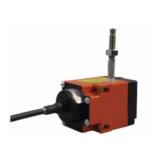
` Seil senkrecht zum Seilausgang führen (siehe Ausfall Seilzuggeber VORSICHT ` Schläge auf den Seilzuggeber vermeiden. ` Keinerlei Veränderung am Gerät vornehmen. Messbereich max. Auszugslänge Abb. 2: Prüfung Auszugslänge SG10 · Datum 14.04.2014 · Art. Nr. 80805 · Änd. Stand 151/14... - Seite 7 Hilfe der Kontermutter und der Einstell- mutter montieren. Schraube M4 (nicht im Lieferum- fang enthalten) Seilaufnahme Abb. 3: Montage Kontermutter Einstellmutter Abb. 4: Seilabschluss-Stück SG10 · Datum 14.04.2014 · Art. Nr. 80805 · Änd. Stand 151/14...
-
Seite 8: Elektrische Montage
Belegung weiß (Endstellung) grün (Schleifer) braun (Anfangsstellung) (Abb. 5, Anschlussbelegung Potentiometer mit R/I-Wandler (MWI) Abb. Der Messwandler liefert einen Schleifenstrom im Bereich von 4 ... 20 mA. Farbe Belegung weiß braun SG10 · Datum 14.04.2014 · Art. Nr. 80805 · Änd. Stand 151/14... - Seite 9 Der Messwandler liefert eine Ausgangsspannung im Bereich von 0 ... 10 V DC. Farbe Belegung weiß grün Uout braun +24 V DC Anschlussbelegung Inkrementalgeber Angaben zu den elektrischen Anschlüssen sind der Dokumentation des Inkrementalgebers zu entnehmen. SG10 · Datum 14.04.2014 · Art. Nr. 80805 · Änd. Stand 151/14...
-
Seite 10: Einstellung Und Abgleich
Pe Trimmpotentio- meter Po Abb. 7: Einstellen Trimmpotis MWI • Mit Trimmpotentiometer Po kann ein Strom von 4 mA bei Potentiome- terwerten von 0 ... 15% des Gesamtwertes eingestellt werden. SG10 · Datum 14.04.2014 · Art. Nr. 80805 · Änd. Stand 151/14... -
Seite 11: Abgleich Des R/U-Wandlers (Mwu)
Der Messwandler ist bei Auslieferung abgeglichen. Anfangsstellung 0 V Ausgangsspannung (Po), entspricht Auszugslänge 0 mm (vollständig ein- gezogen). Endwert 10 V Ausgangsspannung (Pe), entspricht der maxima- len Auszugslänge des Gebers (vollständig ausgezogen). SG10 · Datum 14.04.2014 · Art. Nr. 80805 · Änd. Stand 151/14... -
Seite 12: Justage Inkrementalgeber (Abb. 10)
Inkrementalgeber drehen lässt. 3. Den Geber gegen den Uhrzeigersinn drehen (in Pfeilrichtung), bis der Referenzpunkt erreicht ist. 4. Schrauben anziehen. 5. Gehäusedeckel schließen und mit Schrauben befestigen. SG10 · Datum 14.04.2014 · Art. Nr. 80805 · Änd. Stand 151/14... -
Seite 13: Inbetriebnahme
Beschädigte Seilzuggeber nicht einbauen. Wartung Bei korrektem Einbau nach Kapitel ist der Seilzuggeber wartungsfrei. Der Seilzuggeber enthält eine Lebensdauerschmierung und muss unter norma- len Betriebsbedingungen nicht nachgeschmiert werden. SG10 · Datum 14.04.2014 · Art. Nr. 80805 · Änd. Stand 151/14... -
Seite 14: Zubehör
1. Anschlussstück auf die Schraubverbindung stecken. 2. Spannhülse in Anschlussstück und Schraubverbindung pres- sen, so werden beide Teile formschlüssig verbunden. Schraubverbindung Anschlussstück Spannhülse Abb. 12: Seilverlängerung SG10 · Datum 14.04.2014 · Art. Nr. 80805 · Änd. Stand 151/14... -
Seite 15: Umlenkrolle
Wenn das Seil nicht lotrecht zum Seilausgang befestigt werden kann, ermöglicht der Einsatz einer Umlenkrolle den Auszug in jede beliebige Richtung. • Zubehör SIKO Art. Nr. "UR". SG10 · Datum 14.04.2014 · Art. Nr. 80805 · Änd. Stand 151/14... -
Seite 16: Technische Daten
IP54 (Inkrementalgeber) EN 60529 Systemdaten Ergänzung Systemgenauigkeit ±0.35% (Potentiometer) in Bezug auf die Messlänge (mm) ±0.1% (Inkrementalgeber) in Bezug auf die Messlänge (mm) Verfahrgeschwindigkeit ≤800 m/s Wiederholgenauigkeit ±0.15 mm SG10 · Datum 14.04.2014 · Art. Nr. 80805 · Änd. Stand 151/14... - Seite 32 SIKO GmbH Weihermattenweg 2 79256 Buchenbach Telefon/Phone + 49 7661 394-0 Telefax/Fax + 49 7661 394-388 E-Mail info@siko.de Internet www.siko.de Service support@siko.de...