Siko SG10 Originalmontageanleitung
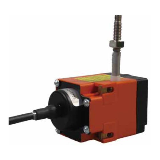
Seilzuggeber
Vorschau ausblenden
Andere Handbücher für SG10:
- Originalmontageanleitung (32 Seiten) ,
- Originalbetriebsanleitung (28 Seiten) ,
- Benutzerinformation (12 Seiten)

Verwandte Anleitungen für Siko SG10


Inhaltszusammenfassung für Siko SG10
- Seite 1 SG10 Seilzuggeber Deutsch Originalmontageanleitung Seite 2 Wire-actuated Encoder English Translation of the Original Installation Instructions page 16 165/16...
-
Seite 2: Inhaltsverzeichnis
5.3 Abgleich des R/U-Wandlers (MWU) 5.4 Justage Inkrementalgeber (Abb. 6 Inbetriebnahme 7 Transport, Lagerung, Wartung und Entsorgung 8 Zubehör Abb. 8.1 Seilverlängerung (Abb. 8.2 Umlenkrolle 9 Technische Daten SG10 · Datum 24.08.2016 · Art. Nr. 80805 · Änd. Stand 165/16... -
Seite 3: Dokumentation
Todesfolge, Sachschäden oder ungeplanten Gerätereaktionen führen können, sofern Sie die gegebenen Anweisungen missachten. Gefährdungen, die zu schweren Körperverletzungen, Sachschäden oder WARNUNG ungeplanten Gerätereaktionen führen können, sofern Sie die gegebenen Anweisungen missachten. SG10 · Datum 24.08.2016 · Art. Nr. 80805 · Änd. Stand 165/16... -
Seite 4: Zielgruppe
Automatisierungstechnik vertraut sind; • als Inbetriebnahme- und Monatagepersonal berechtigt sind, Strom- kreise und Geräte/Systeme gemäß den Standards der Sicherheitstech- nik in Betrieb zu nehmen, zu erden und zu kennzeichnen. SG10 · Datum 24.08.2016 · Art. Nr. 80805 · Änd. Stand 165/16... -
Seite 5: Grundlegende Sicherheitshinweise
Federgehäuse Abb. 1: Federgehäuse 3 Identifikation Das Typenschild zeigt den Gerätetyp mit Variantennummer. Die Lieferpa- piere ordnen jeder Variantennummer eine detaillierte Bestellbezeichnung z. B. SG10 0023 Varianten-Nr. Geräte-Typ SG10 · Datum 24.08.2016 · Art. Nr. 80805 · Änd. Stand 165/16... -
Seite 6: Installation
(Befestigungsmaße siehe Datenblatt). 2. Das Seilabschluss-Stück ( ) beziehungsweise das Seil bis an die vorgesehene Befestigungsstelle ausziehen. 3. Die Seilaufnahme mit Hilfe der Kontermutter und der Einstell- mutter montieren. SG10 · Datum 24.08.2016 · Art. Nr. 80805 · Änd. Stand 165/16... -
Seite 7: Elektrische Montage
Zulässige Leistungsaufnahme ACHTUNG Die Versorgung für den Seilzuggeber ist ausreichend zu dimensionieren. Die Spannungswerte sind abhängig von der Geräteausführung und sind den technischen Daten in Kapitel zu entnehmen. SG10 · Datum 24.08.2016 · Art. Nr. 80805 · Änd. Stand 165/16... - Seite 8 Der Messwandler liefert eine Ausgangsspannung im Bereich von 0 ... 10 V DC. Farbe Belegung weiß grün Uout braun +24 V DC Anschlussbelegung Inkrementalgeber Angaben zu den elektrischen Anschlüssen sind der Dokumentation des Inkrementalgebers zu entnehmen. SG10 · Datum 24.08.2016 · Art. Nr. 80805 · Änd. Stand 165/16...
-
Seite 9: Einstellung Und Abgleich
Trimmpotentio- meter Po Abb. 6: Einstellen Trimmpotentiometer MWI • Mit Trimmpotentiometer Po kann ein Strom von 4 mA bei Potentiome- terwerten von 0 ... 15 % des Gesamtwertes eingestellt werden. SG10 · Datum 24.08.2016 · Art. Nr. 80805 · Änd. Stand 165/16... -
Seite 10: Abgleich Des R/U-Wandlers (Mwu)
Der Messwandler ist bei Auslieferung abgeglichen. Anfangsstellung 0 V Ausgangsspannung (Po), entspricht Auszugslänge 0 mm (vollständig ein- gezogen). Endwert 10 V Ausgangsspannung (Pe), entspricht der maxima- len Auszugslänge des Gebers (vollständig ausgezogen). SG10 · Datum 24.08.2016 · Art. Nr. 80805 · Änd. Stand 165/16... -
Seite 11: Justage Inkrementalgeber (Abb. 9)
Inkrementalgeber drehen lässt. 3. Den Geber gegen den Uhrzeigersinn drehen (in Pfeilrichtung), bis der Referenzpunkt erreicht ist. 4. Schrauben anziehen. 5. Gehäusedeckel schließen und mit Schrauben befestigen. SG10 · Datum 24.08.2016 · Art. Nr. 80805 · Änd. Stand 165/16... -
Seite 12: Inbetriebnahme
Beschädigte Seilzuggeber nicht einbauen. Wartung Bei korrektem Einbau nach Kapitel ist der Seilzuggeber wartungsfrei. Der Seilzuggeber enthält eine Lebensdauerschmierung und muss unter norma- len Betriebsbedingungen nicht nachgeschmiert werden. SG10 · Datum 24.08.2016 · Art. Nr. 80805 · Änd. Stand 165/16... -
Seite 13: Zubehör
Schraubverbindung stecken. 2. Spannhülse in Anschlussstück und Schraubverbindung pres- sen, so werden beide Teile formschlüssig verbunden. Schraubverbindung Anschlussstück Spannhülse Abb. 11: Montage Seilverlängerung SG10 · Datum 24.08.2016 · Art. Nr. 80805 · Änd. Stand 165/16... -
Seite 14: Umlenkrolle
Elektrische Daten Geber Potentiometer Ergänzung Belastbarkeit 1.5 W bei 70 °C Widerstand 10 kΩ Widerstandstoleranz ±5 % Standard-Endwiderstand ≤0.5 % oder 1 Ω (es gilt jeweils der größere Wert) Linearitätstoleranz ±0.25 % ±0.1 % Gebertyp MWI/0,1 SG10 · Datum 24.08.2016 · Art. Nr. 80805 · Änd. Stand 165/16... - Seite 15 Messwandler relative Luftfeuchtigkeit Betauung nicht zulässig EN 61000-6-2 Störfestigkeit / Immission EN 61000-6-4 Störaussendung / Emission Schutzart IP50 (Geberteil Potentiome- EN 600529 ter) IP54 (Inkremental) EN 600529 SG10 · Datum 24.08.2016 · Art. Nr. 80805 · Änd. Stand 165/16...
- Seite 30 SG10...
- Seite 31 SG10...
- Seite 32 SIKO GmbH Weihermattenweg 2 79256 Buchenbach Telefon/Phone + 49 7661 394-0 Telefax/Fax + 49 7661 394-388 E-Mail info@siko.de Internet www.siko-global.com Service support@siko.de...