Inhaltsverzeichnis
Werbung
Verfügbare Sprachen
Verfügbare Sprachen
Quicklinks
PatioControl
Pergola-Steuerung / Pergola Control Unit / Commande de pergola /
Unità di controllo pergola / Mando de pérgola
[TN: 2011781]
Montageanleitung
DE
Bitte bewahren Sie die Montageanleitung auf!
Operating instructions
EN
Please take care of the operating instructions!
Instructions de montage
FR
Veuillez conserver les présentes instructions de montage!
Istruzioni per l'uso
IT
La preghiamo di conservare le istrzioni per l'uso!
Instrucciones de montaje
ES
Por favor, conserve estas instrucciones de montaje!
Werbung
Inhaltsverzeichnis
Fehlerbehebung

Verwandte Anleitungen für elero PatioControl


Inhaltszusammenfassung für elero PatioControl
- Seite 1 PatioControl Pergola-Steuerung / Pergola Control Unit / Commande de pergola / Unità di controllo pergola / Mando de pérgola Montageanleitung Bitte bewahren Sie die Montageanleitung auf! Operating instructions Please take care of the operating instructions! Instructions de montage Veuillez conserver les présentes instructions de montage! Istruzioni per l‘uso...
- Seite 2 Originalmontageanleitung Änderungen vorbehalten. Alle Rechte für den Fall der Patent-, Gebrauchsmuster- oder Geschmacksmustereintragung vorbehalten. Translation from the original German version Subject to change without notice. All rights reserved in the event of registration of patents, working models or design patents. Traduction à...
-
Seite 3: Inhaltsverzeichnis
Inhaltsverzeichnis Allgemeines ....................................... 3 Hinweise zur Montageanleitung ..............................3 Normen und Richtlinien ................................. 3 Bestimmungsgemäße Verwendung ............................3 Vorhersehbarer Fehlgebrauch ..............................4 Gewährleistung und Haftung ............................... 4 Kundendienst des Herstellers ..............................5 Sicherheit ......................................6 Allgemeine Sicherheitshinweise ..............................6 Gestaltung der Sicherheitshinweise ............................6 Sicherheitsgrundsätze .................................. - Seite 4 Einlernen des Funkhandsenders ...............................17 Funktionen der Schalter und LED .............................19 Löschen des aktuellen Funkkanals in der Steuerung ......................22 Löschen aller Kanäle in der Steuerung ............................22 Einlernen der Endlagen der Antriebe ............................24 Stromwerte .....................................25 Bedienung .......................................26 Einlernen eines Wettersensors Sensero/Sensero plus ......................27 Funktionen der Pergola mit dem Wettersensor Sensero/Sensero plus ................30 Schwellwerte der Sensoren ................................31 Verzögerungszeiten ..................................32...
-
Seite 5: Allgemeines
Allgemeines Hinweise zur Montageanleitung Die inhaltliche Gliederung ist an den Lebensphasen der Steuerung PatioControl orientiert. Der Hersteller behält sich Änderungen der in dieser Montageanleitung genannten technischen Daten vor. Sie können im Einzelnen von der jeweiligen Ausführung des Geräts abweichen, ohne dass die sachlichen Informationen grundsätzlich verändert werden und an Gültigkeit verlieren. -
Seite 6: Vorhersehbarer Fehlgebrauch
Betreiber. Für Personen- und Sachschäden, die durch Missbrauch oder aus Verfahrensfehlern, durch unsachgemäße Bedienung und Inbetriebnahme entstehen, übernimmt der Hersteller keine Haftung. Erst bei bestimmungsgemäßer Verwendung ist der sichere und fehlerfreie Gebrauch und die Betriebssicherheit des Geräts gewährleistet. Zur bestimmungsgemäßen Verwendung gehört die Beachtung und Einhaltung aller in dieser Anleitung aufgeführten Sicherheitshinweise. -
Seite 7: Kundendienst Des Herstellers
Das Gerät darf im Fehlerfall nur durch den Hersteller repariert werden. Die Anschrift zum Einsenden an den Kundendienst finden Sie auf der hinteren Umschlagseite. Sollten Sie das Gerät nicht direkt von elero bezogen haben, wenden Sie sich an den Hersteller der Maschine oder den Lieferanten des Geräts. -
Seite 8: Sicherheit
Sicherheit Allgemeine Sicherheitshinweise Diese Anleitung enthält alle Sicherheitshinweise, die zur Vermeidung und Abwendung von Gefahren im Umgang mit der Steuerung „PatioControl“ zu beachten sind. Bei Einhaltung aller aufgeführten Sicherheitshinweise ist eine sichere Benutzung des Geräts gewährleistet. Gestaltung der Sicherheitshinweise Die Sicherheitshinweise in diesem Dokument werden durch Sicherheitssymbole gekennzeichnet und sind nach dem SAFE-Prinzip gestaltet. -
Seite 9: Sicherheitsgrundsätze
Verwendung können Gefahren für Leib und Leben des Benutzers oder Dritter bzw. Beeinträchtigungen des Geräts und anderer Sachwerte entstehen. Unfälle oder Beinaheunfälle beim Gebrauch des Geräts, die zu Verletzungen von Personen und/oder Schäden in der Arbeitsumgebung führten oder geführt hätten, müssen dem Hersteller direkt und unverzüglich gemeldet werden. Sicherheit PatioControl... -
Seite 10: Allgemeine Betreiberpflichten
Alle in der Anleitung und am Gerät aufgeführten Sicherheitshinweise sind zu beachten. Ergänzend zu diesen Sicherheitshinweisen hat der Betreiber dafür zu sorgen, dass alle im jeweiligen Einsatzland geltenden nationalen und internationalen Regelwerke sowie weitere verbindliche Regelungen zur betrieblichen Sicherheit, Unfallverhütung und zum Umweltschutz eingehalten werden. -
Seite 11: Sicherheitshinweise Zum Technischen Zustand
Regeln und Bestimmungen der Berufsgenossenschaft, insbesondere den Vorgaben der DIN VDE 0100, vorgenommen werden. Weiterhin sind die nationalen gesetzlichen Vorschriften des jeweiligen Einsatzlandes zu beachten. • Bei Mängeln, wie lose Verbindungen oder defekte oder beschädigte Kabel, darf das Gerät nicht in Betrieb genommen werden. Sicherheit PatioControl... - Seite 12 • Bei Störungen an der elektrischen Ausrüstung ist das Gerät sofort abzuschalten. • Vor Inspektions-, Montage- und Demontagearbeiten ist das Gerät spannungsfrei zu schalten. • Das Gerät darf nicht mit einem Hochdruckreiniger oder Dampfstrahler abgespritzt werden. Vor dem Anschluss an das Stromnetz muss Folgendes geprüft werden: •...
-
Seite 13: Aufbau/Beschreibung
2,0 A Betriebstemperaturbereich -20 °C 20 °C 50 °C Schutzgrad Steuerung und Netzteil Schutzart IP 65 - nach VDE 0470/DIN 40050/EN 60529 Einbaulage beliebig Gehäusemaße 190 x 75 x 75 mm (ohne Verschraubungen) Farbe silbergrau Funkfrequenz 868 MHz/915 MHz Aufbau/Beschreibung PatioControl... - Seite 14 Technische Daten Steuerung und Netzteil Minimal Nominal Maximal Funksystem elero bidirektional Anzahl der verwendbaren Sender Anzahl Nennspannung 24 V DC Antriebe Leistung 50 W Endabschaltung Endschalter oder Schließkraft Laufzeit 3 min Art der Beleuchtung LED (gemeinsamer Pluspol) Anzahl der Lichtkanäle...
-
Seite 15: Lieferumfang
Lieferumfang • Steuerung PatioControl • Netzteil 230 V/AC / 24 V/DC 150 W oder 240 W • Handsender Variotel2, Tempotel2 oder Multitel2 • Temperatursensor (optional) • optionaler Wettersensor Sensero 868 AC oder Sensero 868 AC Plus • Montageanleitung Aufbau/Beschreibung PatioControl... -
Seite 16: Anschließen Der Steuerung
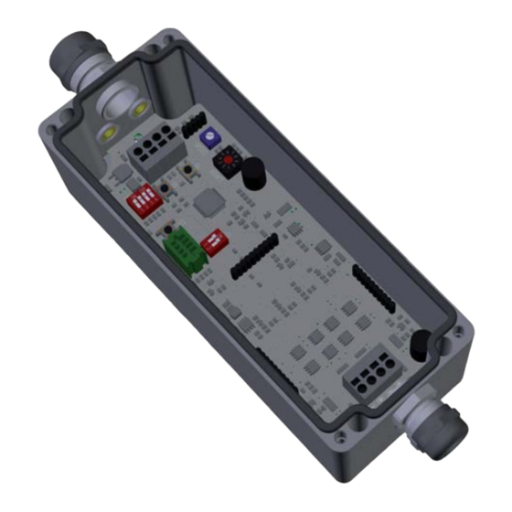
Anschließen der Steuerung GEFAHR DURCH ELEKTRISCHE SPANNUNG, STROMSCHLAG Elektroarbeiten nur durch eine autorisierte Elektrofachkraft ausführen lassen. ACHTUNG Beschädigung des Geräts durch falsche Montage f Schutzart beachten. Netzteil Temperaturfühler Lichtleitungen Motor M2 Motor M1 HINWEIS Für die Lichtleitungen [3] ist optional ein Mehrfachdichteinsatz 4 x 4 mm erhältlich. - Seite 17 3. Schließen Sie einen optionalen Temperatursensor an die Klemmen „T+“ und „T-“ an. FORCE HINWEIS Montieren Sie den Temperatursensor im Außenbereich und in der Nähe der Lamellen. Option: 4. Schließen Sie bei Bedarf einen zweiten Antrieb an die Klemmen „M2+“ und „M2-“ an. Aufbau/Beschreibung PatioControl...
-
Seite 18: Bauseitiger Elektrischer Anschluss
Bauseitiger elektrischer Anschluss Das mitgelieferte Netzteil ist bauseits durch den Betreiber an eine geeignete 230 V AC Spannungsversorgung anzuschließen. ACHTUNG Das Gehäuse des Netzteils ist kundenseitig mit dem PE-Leiter der Zuleitung zu verbinden. Zeichen und Begriffsklärung • ZWP-1: Zwischenposition 1 Standardwert = ca. -
Seite 19: Einlernen Des Funkhandsenders
Display Menütaste links Bedienelemente Funkhandsender Menütaste rechts Beispiel: Tempotel2, Multitel2 Joystick Anzeige Betriebsmodus AUF-Taste STOPP-Taste Statusanzeige AB-Taste Auswahltaste Lerntaste P HINWEIS Die Anordnung der Bedienelemente kann bei anderen Funkhandsendern abweichen. Informationen finden Sie unter: •fwww.elero.de/de/produkte/steuerungen •fwww.elero.com/en/products/control-systems PatioControl [Einlernen des Funkhandsenders]... - Seite 20 Überblick Grundmodul Taster „S4“: Pergola schließen Taster „S5“: Pergola öffnen Schalter „S2“: Auswahl der Optionen 1 ... Sperre bei < -5 °C 2 ... Schneefunktion 3 ... nur ein Antrieb (M1) 4 ... Fahrtrichtung Regenalarm Taster „S3“: Endlagen zurücksetzen (Reset) Taster „S1“: Versorgungsspannung 1 ...Funkempfänger Antrieb 2 ...
-
Seite 21: Funktionen Der Schalter Und Led
Temperatursensor Taster Ein optionaler Temperatursensor ist notwendig, um die Funktionen Schnee, Schutz vor Anfrieren und >3 s drücken: Löschen der Endlagen Antriebssperre bei Temperaturen < -5 ºC nutzen zu können. Pergola schließen Pergola öffnen *) Werkseinstellung PatioControl [Einlernen des Funkhandsenders]... - Seite 22 Handlung Modul Handlung Ergebnis 1. Schließen Sie einen oder zwei Antriebe an die Steuerung an. 2. Schließen Sie die 24 V Seite des Netzteils an die Steuerung an. 3. Schließen Sie die 230 V AC Versorgungs- •fGrüne LED blinkt oder leuchtet spannung an das Netzteil an und schalten Sie diese EIN.
- Seite 23 12. Beim Beginn des Schließens kurz die •fDie Pergola stoppt. Taste AB am Handsender drücken. •fDas Einlernen ist beendet. 13. Schalten Sie S1: •fDie Betriebsbereitschaft ist hergestellt •fDIP-1 = ON •fDIP-2 = ON Einlernen ist beendet. Prüfen Sie die Funktionen des Handsenders. Einlernen des Funkhandsenders PatioControl...
-
Seite 24: Löschen Des Aktuellen Funkkanals In Der Steuerung
Löschen des aktuellen Funkkanals in der Steuerung Modul Handlung Ergebnis 1. Wählen Sie am Handsender den gewünschten •fAnzeige des Kanals am Handsender Funkkanal für das Einlernen aus. 2. Schalten Sie die Spannungsversorgung der Steuerung •fDie Lernbereitschaft ist für 5 min hergestellt. aus und nach 5 s wieder ein. - Seite 25 Deaktivieren Sie diese Schaltzeiten nach Bedarf im Handsender (siehe Anleitung Handsender). HINWEIS Liegen beide Zwischenpositionen auf einem Punkt, löschen Sie alle eingelernten Sender. Drücken Sie dazu für 6 s gleichzeitig die STOPP-, AUF-, AB- und P-Taste. Lernen Sie anschließend alle Sender neu ein. Einlernen des Funkhandsenders PatioControl...
-
Seite 26: Einlernen Der Endlagen Der Antriebe
Einlernen der Endlagen der Antriebe Modul Handlung Ergebnis 1. Einstellen der Geschwindigkeit: •fRechtsdrehen = schneller SPEED •fLinksdrehen = langsamer Vorzugswert: maximaler Speed 2. Einstellen der Abschaltkraft: •fStufe 0 = wenig Kraft FORCE •fStufe 9 = viel Kraft Stufe nur so hoch wie nötig wählen! 3. -
Seite 27: Stromwerte
•fPergola stoppt an ZWP-2 (Standard 66 % Drücken Sie den AUF-Taster zweimal offen). kurz hintereinander. Stromwerte Schalterstellung Abschaltstrom Drehschalter •f0,20 A •f0,40A •f0,60 A •f0,80 A •f1,00 A •f1,20 A •f1,40 A •f1,60 A •f1,80 A •f2,00 A Einlernen der Endlagen der Antriebe PatioControl... -
Seite 28: Bedienung
Bedienung Modul Handlung Ergebnis Voraussetzungen •fDer Handsender ist eingelernt. •fDer richtige Kanal am Handsender ist eingestellt. •fDie Weggrenzen der Antriebe sind eingelernt. •fKurzes Drücken der AUF-Taste •fPergola wird auf das Maximum von 100 % geöffnet •fKurzes Drücken der AB-Taste •fPergola wird auf das Minimum von 0 % geschlossen •fAUF-Taste doppelt drücken •fPergola fährt in ZWP-2 (ca. -
Seite 29: Einlernen Eines Wettersensors Sensero/Sensero Plus
Empfohlene Sensoren: • Sensero-868 AC (ohne Regenfunktion) • Sensero-868 AC-Plus (mit Regenfunktion) HINWEIS Der Windsensor wird durch Abziehen der Schutzkappe aktiviert. HINWEIS Montieren Sie den Sensero/Sensero plus so, dass er alle Witterungseinflüsse erfassen kann. PatioControl [Einlernen eines Wettersensors Sensero/Sensero plus]... - Seite 30 Sensero EIN. 4. Stellen Sie das Lichtpoti auf einen Wert zwischen 2 und 9 ein. HINWEIS Stellen Sie am Sensero den Sichtschutzmodus ein. (siehe Anleitung Sensero/Plus: www.elero.de/de/produkte/steuerungen/ sensero-868-ac-plus/) 6. Schalten Sie S1: Deaktivieren der Funkempfänger •fDIP-1 = OFF •fDIP-2 = OFF...
- Seite 31 12. Prüfen Sie die Funktionen: •fPergola öffnet. •fTaste WIND/AUF •fPergola stoppt. •fTaste P/STOPP •fPergola schließt. •fTaste SONNE/AB 13. Schalten Sie S1: •fDie Betriebsbereitschaft ist hergestellt. •fDIP-1 = ON und DIP-2 = ON Das Einlernen ist beendet. Einlernen eines Wettersensors Sensero/Sensero plus PatioControl...
-
Seite 32: Funktionen Der Pergola Mit Dem Wettersensor Sensero/Sensero Plus
Funktionen der Pergola mit dem Wettersensor Sensero/Sensero plus Licht •fÜberschreiten des eingestellten Lichtschwellwertes: Pergola öffnet auf ZWP-1 (ca. 33 % geöffnet). •fUnterschreiten des eingestellten Lichtschwellwertes: Pergola öffnet 100 %. Dämmerung •fautomatisches Schließen der Pergola am Abend •fautomatisches Öffnen am Morgen erst bei Überschreiten des eingestellten Lichtschwellwertes Regen •fRegen über der eingestellten Schwelle: Pergola schließt vollständig. -
Seite 33: Schwellwerte Der Sensoren
Schwellwerte der Sensoren Wind Licht Wind- Windge- Windge- Licht- Wert in schwelle schwindig- schwindig- schwelle Kilolux keit m/s keit km/h PatioControl [Einlernen eines Wettersensors Sensero/Sensero plus]... -
Seite 34: Verzögerungszeiten
Verzögerungszeiten Störungen • Bereitschaft Regenerkennung: Sensero lost 2 min nach dem Einschalten des Sensero Ursache: • Regensperre bis zum erneuten Reagieren • 15 min kein Signalempfang von einem eingelernten auf Regen: 15 min Sensero • Sensero stromlos oder defekt • Regensperre bis zum erneuten Reagieren auf Sonne: 15 min Folgen: •... -
Seite 35: Lichtmodul
Schalten Sie die Steuerung spannungsfrei. Setzen Sie das Lichtmodul zunächst am hinteren Steckverbinder auf die Grundplatine auf. Senken Sie das Lichtmodul langsam ab, bis alle Stifte in den Buchsen liegen. Drücken Sie das Lichtmodul fest auf die Grundplatine. Lichtmodul PatioControl... -
Seite 36: Überblick
Überblick DIP-Schalter S1: •fDIP-1 = Lichtkanal 1 (z. B. Rot) •fDIP-2 = Lichtkanal 2 (z. B. Grün) •fDIP-3 = Lichtkanal 3 (z. B. Blau) •fDIP-4 = Lichtkanal 4 (z. B. Weiß) •fDIP-5 = Testbetrieb •fDIP-6 = Reserve * Werkseinstellung: Alle OFF Buchse für Funkstick Lichtkanal 1: z. -
Seite 37: Einlernen Des Handsenders Für Das Lichtmodul
•fAnzeige des Kanals im Display oder an der Funkkanal für das Einlernen aus. Kanalanzeige. 7. Wahlen Sie am Lichtmodul den gewünschten Lichtkanal aus (Beispiel Licht 1 (rot)). 8. Schalten Sie an der Steuerung S1: Die Funkempfänger sind deaktiviert. •fDIP-1 = OFF •fDIP-2 = OFF Lichtmodul PatioControl... - Seite 38 Modul Handlung Ergebnis 9. Schalten Sie nach ca. 5 s an der Die Lernbereitschaft ist jetzt für 5min aktiviert. Steuerung S1: •fDIP-1 = OFF •fDIP-2 = ON 10. Drücken Sie für ca. 1 s die •fStatus LED leuchtet 1x orange P-Taste auf der Rückseite.
-
Seite 39: Fehlerbehebung
Beheben des Kurzschlusses. auf der Motorleitung. abklemmen und prüfen. Der Antrieb fährt kurz an und Die Belastung ist zu groß. Den Regler „FORCE“ auf bleibt wieder stehen. der Platine auf eine höhere Stufe stellen. Prüfen der Pergola auf mögliche Schwergängigkeiten. Fehlerbehebung PatioControl... - Seite 40 Fehler/Störung Mögliche Ursache Prüfung Lösung Die Anschlussleitungen sind Mit S4 und S5 die Die beiden Anschlussdrähte vertauscht. Drehrichtung prüfen an der Klemme auf der Der Antrieb fährt in die (S4 = Schließen der Pergola). Platine vertauschen. falsche Richtung. Der Antrieb wurde falsch Fahrtrichtung mittels Funkkanal löschen, eingelernt.
- Seite 41 Beschattungs- oder Antrieb alle Sender löschen liegen auf einem Punkt. Wendeposition einzulernen. und den richtigen Sender neu einlernen. HINWEIS Wenn der Sensero und die Steuerung komplett ausgeschaltet und nach wenigen Sekunden wieder eingeschaltet werden, sind alle Wartezeiten zurückgesetzt. Fehlerbehebung PatioControl...
-
Seite 42: Einbauerklärung
Einbauerklärung HINWEIS Die vollständige Einbauerklärung finden Sie im Downloadbereich unserer Internetpräsenz: www.elero-linear.de/downloads. -
Seite 43: Entsorgung
Bei der Entsorgung der Steuerung sind die zu diesem Zeitpunkt gültigen internationalen, nationalen und regionalspezifischen Gesetze und Vorschriften einzuhalten. HINWEIS Achten Sie darauf, dass stoffliche Wiederverwertbarkeit, Demontier- und Trennbarkeit von Werkstoffen und Baugruppen ebenso berücksichtigt werden, wie Umwelt- und Gesundheitsgefahren bei Recycling und Entsorgung. Entsorgung PatioControl... -
Seite 44: Anhang
Anhang Bohrmaße Maßstab 1:1... - Seite 45 Inhaltsverzeichnis General ....................................... 3 Notes on the installation instructions ............................3 Standards and guidelines ................................3 Use in line with intended use ............................... 3 Foreseeable misuse ..................................4 Guarantee and liability ................................... 4 Customer service of the manufacturer ............................5 Safety ........................................
- Seite 46 Teach-in hand-held transmitter ..............................17 Functions of the switches and LEDs ............................19 Delete the current radio channel in the control unit ......................22 Deleting all radio channels in the control unit ........................22 Teach-in of the limit positions of the actuators ........................24 Current values ....................................25 Operation ......................................26 Teach-in Sensero/Sensero plus weather sensor ........................27 Functions of the pergola with the Sensero/Sensero plus weather sensor ..............30...
-
Seite 47: General
General Notes on the installation instructions The contents are classified by the service life phases of the PatioControl control unit. The manufacturer reserves the right to make changes to the technical specifications stated in these installation instructions. In detail these can differ from the respective version of the device without the factual information being fundamentally changed and without losing their validity. -
Seite 48: Foreseeable Misuse
assumes no liability for personal injury or damage to property caused by misuse or procedural errors, improper operator control or improper start of operation. Safe and fault-free operation and reliability of the devices can be guaranteed only when it is used as intended. Proper use also includes compliance with and observance of all safety instructions contained in this manual. -
Seite 49: Customer Service Of The Manufacturer
The device may be repaired only by the manufacturer in the event of a fault. The address for sending the device to the customer service department can be found on the inside of the back cover. If you have not purchased the device directly from elero, please contact the manufacturer of the machine or the supplier of the device. -
Seite 50: Safety
These instructions contain all safety instructions that must be observed to avoid and prevent dangers in working with the PatioControl control unit. Safe use of the device is guaranteed when all the specified safety notices and directions are complied with. -
Seite 51: Safety Principles
All work on the device must be performed only by trained and authorised personnel who have been instructed on safety. Safety PatioControl... -
Seite 52: General Duties Of The Plant Operator
General duties of the plant operator • The operator is obligated to use the device only when it is in perfect working order and is safe to operate. The operator must ensure that, in addition to the safety information in the instructions, the generally accepted safety and accident-prevention regulations, the specifications of DIN VDE 0100 and the provisions relating to environmental protection of the respective country of use are observed and complied with. -
Seite 53: Safety Information On The Technical Condition
• In the event of any defects, such as loose connections or defective or damaged cables, the device must not be put into operation. • In the event of faults with the electrical equipment, the device must be switched off immediately. • The device must be de-energised before any inspection, installation or dismantling work. Safety PatioControl... - Seite 54 • The device must not be hosed down with a high-pressure cleaner or steam jet. The following must be checked before connecting the device to the power supply: • Are all electrical connections, safety devices, fuses, etc. properly installed, connected and earthed? •...
-
Seite 55: Structure/Description
50 °C Degree of protection of control unit and power Degree of protection IP 65 - as per VDE 0470/DIN 40050/EN 60529 supply Installation position user-defined Housing dimensions 190 x 75 x 75 mm (without screw fastenings) Colour silver-grey Structure/description PatioControl... - Seite 56 Technical data of control unit and power supply Radio frequency 868 MHz / 915 MHz Minimum Nominal Maximum Radio system elero bidirectional Number of usable transmitters Number Rated voltage 24 V DC Actuators Performance 50 W Limit switch Limit switches or closing force...
-
Seite 57: Items Supplied
Items supplied • PatioControl control unit • Power supply 230 V/AC / 24 V/DC 150 W or 240 W • Variotel2, Tempotel2 or Multitel2 hand-held transmitter • Temperature sensor (optional) • optional Sensero 868 AC or Sensero 868 AC Plus weather sensor •... -
Seite 58: Connection Of The Control Unit
Connection of the control unit DANGER DUE TO AN ELECTRICAL VOLTAGE, ELECTRIC SHOCK Electrical work must only be performed by an authorised electrician. WARNING Damage to the device through incorrect assembly f Observe the protection class. Power supply Temperature sensor Light cables Motor M2 Motor M1... - Seite 59 3. Connect an optional temperature sensor to the T+ and T- terminals. FORCE NOTE Install the temperature sensor outside and close to the slats. Option: 4. If necessary, connect a second actuator to the M2+ and M2- terminals. Structure/description PatioControl...
-
Seite 60: Building Electrical Connection
Building electrical connection The operator must connect the included power supply to a suitable 230 V AC power supply. WARNING The housing of the power supply must be connected to the PE conductor of the feed line at the customer. Icons and explanation of terms •... -
Seite 61: Teach-In Hand-Held Transmitter
Display of operating mode DOWN key STOP key Status indicator DOWN key Selector key Teach-in key P NOTE The layout of the controls may be different on other hand- held transmitters. For information see: •fwww.elero.de/de/produkte/steuerungen •fwww.elero.com/en/products/control-systems PatioControl [Teach-in hand-held transmitter]... - Seite 62 Overview of base module "S4" key: close pergola "S5" key: open pergola "S2" switch: select options 1 ... lock at < -5 °C 2 ... snow function 3 ... only one actuator (M1) 4 ... rain alarm direction of travel "S3"...
-
Seite 63: Functions Of The Switches And Leds
An optional temperature sensor is required in order to be able to use the snow, protection from freezing and press and hold >3 s: delete limit positions actuator lock at temperatures < -5 ºC. close pergola open pergola *) factory setting PatioControl [Teach-in hand-held transmitter]... - Seite 64 Handling Module Handling Result 1. Connect one or two actuators to the control unit. 2. Connect the 24 V side of the power supply to the control unit. 3. Connect the 230 V AC supply voltage •fGreen LED flashes or is steady to the power supply and switch it to ON.
- Seite 65 •fThe pergola stops. DOWN key on the hand-held transmitter. •fThe teach-in process is complete. 13. Switch S1: •fThe teach-in mode is set •fDIP-1 = ON •fDIP-2 = ON Teach-in is complete. Check the functions of the hand-held transmitter. Teach-in hand-held transmitter PatioControl...
-
Seite 66: Delete The Current Radio Channel In The Control Unit
Delete the current radio channel in the control unit Module Handling Result 1. Select the desired radio channel for teach-in the hand- •fDisplay of the channel on the hand-held held transmitter. transmitter 2. Switch the control unit power supply off and then on •fThe teach-in mode is set for 5 min. - Seite 67 NOTE If both intermediate positions are at one position, delete all teached-in transmitters. Press and hold the STOP, UP, DOWN and P-keys simultaneously for 6 s to delete the positions. Then teach in all transmitters again. Teach-in hand-held transmitter PatioControl...
-
Seite 68: Teach-In Of The Limit Positions Of The Actuators
Teach-in of the limit positions of the actuators Module Handling Result 1. Adjustment of speed: •frotate right = faster SPEED •frotate left = slower Optimum value: maximum speed 2. Adjustment of cut-out force: •fstep 0 = low force FORCE •fstep 9 = high force Only select a step as high as necessary! 3. -
Seite 69: Current Values
Current values Switch position Cut-off current of rotary switch •f0.20 A •f0.40 A •f0.60 A •f0.80 A •f1.00 A •f1.20 A •f1.40 A •f1.60 A •f1.80 A •f2.00 A Teach-in of the limit positions of the actuators PatioControl... -
Seite 70: Operation
Operation Module Handling Result Prerequisites •fThe hand-held transmitter is teached-in. •fThe correct channel on the hand-held transmitter is set. •fThe path limits of the actuators are teached-in. •fBriefly press the UP key •fPergola is opened to the maximum 100% •fBriefly press the DOWN key •fPergola is closed to the minimum 0% •fPress DOWN key twice •fPergola moves to INT-2 (approx. -
Seite 71: Teach-In Sensero/Sensero Plus Weather Sensor
• Sensero-868 AC (without rain function) • Sensero-868 AC-Plus (with rain function) NOTE The wind sensor is activated by removing the protective cap. NOTE Install the Sensero/Sensero plus so it can detect all weather conditions. PatioControl [Teach-in Sensero/Sensero plus weather sensor]... - Seite 72 Sensero to ON. 4. Set the light potentiometer to a value between 2 and 9. NOTE Set the Sensero to the privacy mode. (see Sensero/Plus instructions: www.elero.de/de/produkte/steuerungen/ sensero-868-ac-plus/) 6. Switch S1: Deactivating the radio receiver •fDIP-1 = OFF •fDIP-2 = OFF...
- Seite 73 12. Check the functions: •fPergola opens. •fWIND/UP key •fPergola stops. •fP/STOP key •fPergola closes. •fSUN/DOWN key 13. Switch S1: •fThe teach-in mode is set. •fDIP-1 = ON and DIP-2 = ON The teach-in process is complete. Teach-in Sensero/Sensero plus weather sensor PatioControl...
-
Seite 74: Functions Of The Pergola With The Sensero/Sensero Plus Weather Sensor
Functions of the pergola with the Sensero/Sensero plus weather sensor Light •fExceeding the set light threshold: Pergola opens to INT-1 (approx. 33% open). •fBelow the set light threshold: Pergola opens 100%. Twilight •fautomatic close of pergola in the evening •fautomatic opening in the morning when the set light threshold is exceeded Rain •frain above the set threshold: pergola closes completely. -
Seite 75: Threshold Values Of The Sensors
Threshold values of the sensors Wind Light Wind Wind Wind Light Value in threshold speed m/s speed threshold kilolux km/h PatioControl [Teach-in Sensero/Sensero plus weather sensor]... -
Seite 76: Delay Times
Delay times Faults • Rain detection mode: Sensero lost 2 min after switching on the Sensero Cause: • Rain lock until new reaction • 15 min no signal received from teached-in Sensero to rain: 15 rpm • Sensero without power or defective •... -
Seite 77: Light Module
Switch off the power supply to the control unit. First place the light module on the rear connector on the PC board. Slowly lower the light module until all pins are in the sockets. Press the light module firmly on the PC board. Light module PatioControl... -
Seite 78: Overview
Overview DIP switch S1: •fDIP-1 = light channel 1 (e.g. red) •fDIP-2 = light channel 2 (e.g. green) •fDIP-3 = light channel 3 (e.g. blue) •fDIP-4 = light channel 4 (e.g. white) •fDIP-5 = test mode •fDIP-6 = reserve * factory setting: All OFF Port for radio stick light channel 1: e.g. -
Seite 79: Teach-In Hand-Held Transmitter For The Light Module
•fDisplay of the channel on the display or on the hand-held transmitter. channel display. 7. On the light module select the desired light channel (for example light 1 (red)). 8. Switch on control S1: The radio receivers are disabled. •fDIP-1 = OFF •fDIP-2 = OFF Light module PatioControl... - Seite 80 Module Handling Result 9. After approx. 5 s switch on The teach-in mode is now activated for 5 min. control S1: •fDIP-1 = OFF •fDIP-2 = ON 10. For approx. 1 s press and hold the •fStatus LED light 1x orange P-key on the back.
-
Seite 81: Fault Rectification
Eliminate the short-circuit. motor wiring. board wiring. The actuator moves briefly The load is too high. Set the FORCE regulator on and then stops. the PC board to a higher level. Check whether the pergola may be stiff. Fault rectification PatioControl... - Seite 82 Error/fault Possible cause Inspection Solution The connection lines are Check the direction of Reverse the two connection reversed. rotation with S4 and S5 wires on the terminal on the (S4 = closes the pergola). PC board. The actuator moves in the wrong direction.
- Seite 83 NOTE If the Sensero and the control unit are switched off completely and then on again after a few seconds, all wait times are reset. Fault rectification PatioControl...
-
Seite 84: Declaration Of Incorporation
Declaration of Incorporation NOTE The complete installation declaration can be found in the download section of our web site: www.elero-linear.de/downloads. -
Seite 85: Waste Disposal
When scrapping the control unit, the currently applicable international, national and regional laws and regulations must be observed. NOTE Ensure that the recycling, dismantling and separation capabilities of the materials and assemblies, as well as the environmental and health dangers, are taken into consideration during recycling and waste disposal. Waste disposal PatioControl... -
Seite 86: Annex
Annex Drill hole sizes Scale 1:1... - Seite 87 Inhaltsverzeichnis Généralités ......................................3 Remarques concernant les instructions de montage ......................3 Normes et directives ..................................3 Utilisation conforme aux prescriptions ............................3 Utilisation non conforme prévisible ............................4 Garantie et responsabilité ................................4 Service après-vente du fabricant ..............................5 Sécurité...
- Seite 88 Programmation de la télécommande ............................17 Fonctions des interrupteurs et LED ............................19 Suppression du canal radio actuel dans la commande .......................22 Suppression de tous les canaux dans la commande ......................22 Programmation des positions de fin de course des moteurs....................24 Valeurs de courant ..................................26 Utilisation ......................................27 Programmation d'une station météo Sensero/Sensero plus .....................28 Fonctionnement de la pergola avec la station météo Sensero/Sensero plus..............31...
-
Seite 89: Généralités
Généralités Remarques concernant les instructions de montage Le plan structurant le contenu est organisé en fonction des phases de vie de la commande PatioControl. Le fabricant se réserve le droit de modifier les caractéristiques techniques mentionnées dans les présentes instructions de montage. Elles peuvent diverger en fonction de la version de l'appareil, sans modification des informations fonctionnelles qui restent valables. -
Seite 90: Utilisation Non Conforme Prévisible
L'exploitant est seul responsable des dommages résultant d'une utilisation de l'appareil non conforme aux prescriptions. Le fabricant décline toute responsabilité pour des dommages corporels et matériels résultant d'abus ou d'erreurs de procédés, ainsi que d'une utilisation et d'une mise en service incorrectes. L'utilisation en toute sécurité... -
Seite 91: Service Après-Vente Du Fabricant
En cas de défaut, l'appareil doit uniquement être réparé par le fabricant. Vous trouverez l'adresse d'envoi au service après-vente sur la couverture de dos. Si vous n'avez pas acheté l'appareil directement auprès d'elero, veuillez vous adresser au constructeur de la machine ou au fournisseur de l'appareil. -
Seite 92: Sécurité
La présente notice comprend toutes les consignes de sécurité à respecter pour éviter et prévenir les risques dans le cadre de l'utilisation de la commande « PatioControl ». Le respect de toutes les consignes de sécurité mentionnées garantit une utilisation de l'appareil en toute sécurité. -
Seite 93: Principes De Sécurité De Base
Les accidents (même évités de justesse) survenus lors de l'utilisation de l'appareil, qui ont (ou auraient) conduit à des blessures de personnes et/ou des endommagements dans l'environnement de travail, doivent être signalés immédiatement et directement au fabricant. Sécurité PatioControl... -
Seite 94: Obligations Générales De L'exploitant
Toutes les consignes de sécurité figurant dans les présentes instructions et sur l'appareil doivent être appliquées. En plus de ces consignes de sécurité, l'exploitant doit s'assurer du respect de toutes les dispositions nationales et internationales applicables dans le pays d'utilisation, ainsi que de toutes les autres réglementations obligatoires en matière de sécurité... -
Seite 95: Consignes De Sécurité Relatives À L'état Technique
édictées par la Caisse d'assurance maladie et aux spécifications de la norme DIN VDE 0100. De plus, les législations nationales en vigueur dans le pays d'utilisation doivent être respectées. • En cas de défauts, comme par exemple des connexions desserrées ou des câbles défectueux ou endommagés, Sécurité PatioControl... - Seite 96 l'appareil ne doit pas être mis en service. • En cas d'apparition de dérangements affectant l'équipement électrique, l'appareil doit être mis immédiatement hors tension. • L'appareil doit être mis hors tension avant tous les travaux de contrôle, de montage et de démontage. •...
-
Seite 97: Montage/Description
50 °C Niveau de protection Commande et bloc Type de protection IP 65 - selon norme VDE 0470/DIN 40050/EN 60529 d'alimentation Emplacement de montage au choix Dimensions du boîtier 190 x 75 x 75 mm (sans raccords vissés) Montage/description PatioControl... - Seite 98 Caractéristiques techniques Commande et bloc d'alimentation Couleur gris argenté Fréquence radio 868 MHz / 915 MHz Minimal Nominal Maximal Système radio elero bidirectionnel Nombre de chaînes utilisables Nombre Tension nominale 24 V c.c Puissance 50 W Moteurs Déclenchement en fin...
-
Seite 99: Étendue De La Livraison
Étendue de la livraison • Commande PatioControl • Bloc d'alimentation 230 V/c.a / 24 V/c.c 150 W ou 240 W • Télécommande Variotel2, Tempotel2 ou Multitel2 • Capteur de température (en option) • Station météo en option Sensero 868 AC ou Sensero 868 AC Plus •... -
Seite 100: Raccordement De La Commande
Raccordement de la commande RISQUE D'ÉLECTRISATION OU D'ÉLECTROCUTION Faire exécuter les travaux d'électricité uniquement par des électriciens autorisés. ATTENTION Risque de destruction de l'appareil due à un mauvais montage f Prendre garde à la classe de protection. Bloc d'alimentation Capteur de température Câbles de lumière Moteur M2 Moteur M1... - Seite 101 3. Raccordez un capteur de température optionnel aux bornes « T+ » et « T- ». FORCE REMARQUE Montez le capteur de température à l'extérieur et à proximité des lattes. Option : 4. Raccordez si nécessaire un deuxième moteur aux bornes « M2+ » et « M2- ». Montage/description PatioControl...
-
Seite 102: Raccordement Électrique Côté Bâtiment
Raccordement électrique côté bâtiment Le bloc d'alimentation fourni doit être raccordé côté bâtiment par l'opérateur à une alimentation électrique 230 V c. a appropriée. ATTENTION Le boîtier du bloc d'alimentation doit être raccordé par le client avec borne de raccordement de l'alimentation. Symboles et définition des termes •... -
Seite 103: Programmation De La Télécommande
Affichage du mode de fonctionnement Touche UP Touche STOP Voyant d'état Touche DOWN Touche de sélection Touche de programmation P REMARQUE L'ordre des commandes peut différer sur d'autres télécommandes. Vous trouverez des informations sur : •fwww.elero.de/de/produkte/steuerungen •fwww.elero.com/en/products/control-systems PatioControl [Programmation de la télécommande]... - Seite 104 Vue d'ensemble du module de base Touche « S4 » : fermer la pergola Touche « S5 » : ouvrir la pergola Interrupteur « S2 » : sélection des options 1 ... blocage si < -5 °C 2 ... fonction de neige 3 ... un seul moteur (M1) 4 ... direction alarme de pluie Touche « S3 » : réinitialiser les positions de fin de course (Reset) Touche « S1 » : tension d'alimentation...
-
Seite 105: Fonctions Des Interrupteurs Et Led
Appuyer >3 s : effacement des positions de fin de course pour pouvoir utiliser les fonctions neige, protection contre le gel et blocage si températures < -5°C. fermer la pergola ouvrir la pergola *) Configuration d'usine PatioControl [Programmation de la télécommande]... - Seite 106 Action Module Action Résultat 1. Raccordez un ou deux moteurs à la commande. 2. Raccordez le côté 24 V du bloc d'alimentation à la commande. 3. Raccordez la tension d'alimentation •fLa LED verte clignote ou s'allume 230 V c. a au bloc d'alimentation et placez-le sur ON.
- Seite 107 DOWN de •fLa programmation est terminée. la télécommande. 13. Actionnez S1 : •fLe fonctionnement est établi •fDIP-1 = ON •fDIP-2 = ON La programmation est terminée. Contrôlez le fonctionnement de la télécommande. Programmation de la télécommande PatioControl...
-
Seite 108: Suppression Du Canal Radio Actuel Dans La Commande
Suppression du canal radio actuel dans la commande Module Action Résultat 1. Sélectionnez le canal radio souhaité sur la •fAffichage des canaux sur la télécommande télécommande pour la programmation. 2. Arrêtez l'alimentation électrique de la commande et •fLa possibilité de programmer est activée pour rétablissez-la au bout de 5 s. - Seite 109 Si les deux positions intermédiaires se trouvent sur un point, supprimez tous les canaux programmés. Pour cela, appuyez simultanément sur les touches STOP, UP, DOWN et la touche P pendant 6 s. Programmez ensuite à nouveau tous les canaux. Programmation de la télécommande PatioControl...
-
Seite 110: Programmation Des Positions De Fin De Course Des Moteurs
Programmation des positions de fin de course des moteurs Module Action Résultat 1. Programmation de la vitesse : •fTourner vers la droite = plus rapide SPEED •fTourner vers la gauche = plus lente Valeur de préférence : vitesse maximale 2. Régler la force de désactivation : •fNiveau 0 = peu de force FORCE •fNiveau 9 = beaucoup de force... - Seite 111 7. Contrôler la position intermédiaire 2 : •fLa pergola s'arrête en position ZWP-2 (ouverte Appuyez deux fois sur la touche UP à 66 % par défaut). rapidement l'une après l'autre. Programmation des positions de fin de course des moteurs PatioControl...
-
Seite 112: Valeurs De Courant
Valeurs de courant Position de Courant de l'interrupteur coupure Bouton rotatif •f0,20 A •f0,40A •f0,60 A •f0,80 A •f1,00 A •f1,20 A •f1,40 A •f1,60 A •f1,80 A •f2,00 A... -
Seite 113: Utilisation
•fLa pergola se met en position ZWP-2 (ouverte à env. 66%). •fAppuyer deux fois sur la touche •fLa pergola se met en position ZWP-1 (ouverte à DOWN env. 33%) •fAppuyer brièvement sur la touche •fLe moteur s'arrête STOP Programmation des positions de fin de course des moteurs PatioControl... -
Seite 114: Programmation D'une Station Météo Sensero/Sensero Plus
Programmation d'une station mé- Touche DOWN/soleil téo Sensero/Sensero plus Touche STOP/P Touche UP/vent Vue d'ensemble Capteur de vent Potentiomètre de crépuscule Potentiomètre de lumière Potentiomètre de pluie Potentiomètre de vent LED de fonctionnement LED de lumière LED d'alarme Capteurs recommandés : •... - Seite 115 4. Réglez le potentiomètre lumineux sur une valeur comprise entre 2 et 9. REMARQUE Réglez le mode de protection visuelle de la Sensero. (voir la notice de la Sensero/Plus : www.elero.de/de/produkte/steuerungen/ sensero-868-ac-plus/) Programmation d'une station météo Sensero/Sensero plus PatioControl...
- Seite 116 Module Action Résultat 6. Actionnez S1 : Désactivez le récepteur radio •fDIP-1 = OFF •fDIP-2 = OFF 7. Branchez S1 au bout de 3 s : •fLa possibilité de programmer est maintenant activée pour 5 min. •fDIP-1 = ON •fDIP-2 = OFF 8.
-
Seite 117: Fonctionnement De La Pergola Avec La Station Météo Sensero/Sensero Plus
•fPassage en dessous de la valeur de seuil de lumière programmée : La pergola s'ouvre à 100%. Crépuscule •fFermeture automatique de la pergola le soir •fOuverture automatique le matin seulement en cas de dépassement de la valeur de seuil de lumière programmée Programmation d'une station météo Sensero/Sensero plus PatioControl... - Seite 118 Pluie •fPluie supérieure au seuil programmé : La pergola se ferme entièrement. •fAlarme de pluie : clignotement 2 fois en 6 s de la LED rouge Neige (uniquement avec le capteur de température) •fPrécipitation supérieure au seuil programmé et température inférieure à 2 °C : La pergola s'ouvre en position ZWP-2 (ouverte env.
-
Seite 119: Valeurs De Seuil Des Capteurs
Valeurs de seuil des capteurs Vent Lumière Seuil de Vitesse de Vitesse de Seuil de Valeur en vent vent m / s vent km/h lumière kilolux PatioControl [Programmation d'une station météo Sensero/Sensero plus]... -
Seite 120: Délais De Temporisation
Délais de temporisation Pannes • Capacité de reconnaissance de la pluie : Sensero lost 2 min après la mise en service de Sensero Cause : • Blocage contre la pluie jusqu'à une nouvelle • pas de signal reçu d'une station Sensero réaction à la programmée pendant 15 min pluie : 15 tr/min •... -
Seite 121: Module Lumineux
Placez ensuite le module lumineux sur la prise arrière de la platine de base. Abaissez le module lumineux lentement, jusqu'à ce que toutes les fiches se trouvent dans les emplacements. Fixez le module lumineux à la platine de base. Module lumineux PatioControl... -
Seite 122: Aperçu
Aperçu Interrupteurs DIP S1 : •fDIP-1 = canal lumineux 1 (p. ex. rouge) •fDIP-2 = canal lumineux 2 (p. ex. vert) •fDIP-3 = canal lumineux 3 (p. ex. bleu) •fDIP-4 = canal lumineux 4 (p. ex. blanc) •fDIP-5 = test •fDIP-6 = réserve * Configuration d'usine : tous OFF Emplacement pour stick radio Canal lumineux 1 : p. -
Seite 123: Programmation De La Télécommande Pour Le Module Lumineux
6. Sélectionnez le canal radio souhaité sur la •fAffichage du canal sur l'écran ou sur l'affichage télécommande pour la programmation. des canaux. 7. Sélectionnez le canal lumineux souhaité sur le module lumineux (par ex. lumière 1 (rouge)). Module lumineux PatioControl... - Seite 124 Module Action Résultat 8. Actionnez sur la commande S1 : Les récepteurs radio sont désactivés. •fDIP-1 = OFF •fDIP-2 = OFF 9. Actionnez au bout d'env. 5 s sur la La possibilité de programmer est maintenant activée pour 5 min. commande S1 : •fDIP-1 = OFF •fDIP-2 = ON 10.
- Seite 125 Module Action Résultat 14. Une fois la programmation terminée, Le fonctionnement est établi. actionnez S1 : •fDIP-1 = ON •fDIP-2 = ON Module lumineux PatioControl...
-
Seite 126: Dépannage
Dépannage Erreur/panne Cause possible Contrôle Solution Le bloc d'alimentation n'est Vérifiez que la LED verte Raccorder le bloc pas raccordé ou coupé. clignote ou s'allume. d'alimentation, éventuellement échanger les Le moteur ne fonctionne pas. fils brun et bleu. La LED-1 verte sur la platine Le moteur est raccordé... - Seite 127 Le moteur ne fonctionne été réactivé. DIP de S1 sur ON. qu'avec les touches S4 et S5 de la platine, pas avec la Le mauvais canal a Programmer le bon canal télécommande. été sélectionné sur la radio. télécommande. Dépannage PatioControl...
- Seite 128 Erreur/panne Cause possible Contrôle Solution La lumière, le vent ou Contrôler la séquence de la pluie a déclenché le clignotement de la LED rouge fonctionnement. sur la platine de commande. Un interrupteur horaire astro Un horaire astro est activé. Désactiver l'horaire astro sur a déclenché.
-
Seite 129: Déclaration D'incorporation
Déclaration d'incorporation REMARQUE Vous trouverez la déclaration d’incorporation complète dans la zone de téléchargement de notre site Internet : www.elero-linear.de/downloads. -
Seite 130: Élimination
Élimination Lors de l'élimination de la commande, il convient de respecter les lois et les prescriptions internationales, nationales et régionales en vigueur. REMARQUE Tenez compte des dangers pour l'environnement et la santé que présente l'élimination sauvage et ne négligez pas les possibilités de recyclage (démontage, séparation des matériaux et des composants puis réutilisation). -
Seite 131: Annexe
Annexe Cotes de perçage Échelle 1:1 Annexe PatioControl... - Seite 133 Inhaltsverzeichnis Panoramica ....................................... 3 Nota alle indicazioni di montaggio .............................. 3 Norme e linee guida ..................................3 Impiego normale ....................................3 Uso scorretto ragionevolmente prevedibile ..........................4 Garanzia e responsabilità ................................4 Servizio clienti a cura del produttore............................5 Sicurezza ......................................6 Disposizioni generali di sicurezza ..............................
- Seite 134 Programmazione del trasmettitore portatile radio .......................17 Funzioni dell’interruttore e LED ..............................19 Cancellazione dei canali radio presenti nell’unità di controllo ...................22 Cancellazione di tutti i canali nell’unità di controllo ......................22 Programmazione dei finecorsa motori ............................24 Valori di tensione ...................................26 Uso ........................................27 Programmazione del sensore meteo Sensero/Sensero plus ....................28 Funzioni della pergola con sensore meteo Sensero/Sensero plus ..................31 Valori di soglia dei sensori ................................32...
-
Seite 135: Panoramica
Panoramica Nota alle indicazioni di montaggio I presente documento fornisce contenuti inerenti alla descrizione del controllo di PatioControl. Il produttore si riserva il diritto di apportare modifiche ai dati tecnici specificati nelle presenti istruzioni di montaggio. Nello specifico, essi potrebbero deviare dalla versione indicata del dispositivo, senza ripercussione sulle informazioni sostanziali che rimangano invariate e valide. -
Seite 136: Uso Scorretto Ragionevolmente Prevedibile
L’affidabilità e il corretto funzionamento del dispositivo sono garantiti solo in caso di uso conforme alle disposizioni riportate in queste istruzioni di montaggio. L’affidabilità e il corretto funzionamento del dispositivo sono garantiti solo in caso di uso conforme alle disposizioni riportate in queste istruzioni di montaggio . -
Seite 137: Servizio Clienti A Cura Del Produttore
In caso di avaria, il dispositivo deve essere riparato esclusivamente dal produttore. Indirizzo del servizio clienti è riportato sul retro della copertina. Qualora non aveste ricevuto il dispositivo direttamente da elero, si prega di rivolgersi al servizio clienti del proprio fornitore . Panoramica... -
Seite 138: Sicurezza
Disposizioni generali di sicurezza In queste istruzioni di montaggio sono riportate le misure di sicurezza per la protezione da rischi in relazione all’uso del dispositivo “PatioControl”. Rispettando tutte le indicazioni di sicurezza, è garantito il corretto funzionamento del dispositivo. Organizzazione delle disposizioni di sicurezza Le indicazioni di sicurezza in questo documento sono riportate sotto forma di simboli di sicurezza e sono elaborate secondo i principi SAFE . -
Seite 139: Principi Di Sicurezza
Rispettare tutte le indicazioni riportate in queste istruzioni di montaggio e sul dispositivo stesso. Oltre alle misure Sicurezza PatioControl... -
Seite 140: Disposizioni Generali Relativi Al Gestore
di sicurezza, il gestore deve conformarsi al quadro normativo nazionale e internazionale in vigore nel luogo di installazione nonché alle altre regole vincolanti per la sicurezza nelle aziende, la prevenzione antinfortunistica e la salvaguardia dell‘ambiente. Le operazioni al dispositivo devono essere eseguite da personale autorizzato, qualificato e istruito in materia di sicurezza. -
Seite 141: Disposizioni Di Sicurezza In Merito Allo Stato Della Tecnica
• In caso di difetti, come collegamenti non ben effettuati o cavi danneggiati, il dispositivo non deve essere messo in funzione. • In caso di danni all’attrezzatura elettrica il dispositivo deve essere immediatamente scollegato. • Prima di eseguire i lavori di montaggio, smontaggio e ispezione, avviare il dispositivo senza tensione. • Sicurezza PatioControl... - Seite 142 • • • Il dispositivo non deve essere nebulizzato con pulitori ad alta pressione o getti di vapore. Prima di effettuare il collegamento all’alimentazione, controllare quanto segue: • Tutti gli allacciamenti elettrici, i dispositivi di sicurezza, le protezioni ecc. sono correttamente installati, collegati e messi a terra?? •...
-
Seite 143: Struttura/Descrizione
Grado di protezione unità di controllo e Grado di protezione IP 65 - ai sensi della norma VDE 0470/DIN 40050/EN alimentatore 60529 Montaggio illimitato Dimensioni 190 x 75 x 75 mm (senza raccordi a vite) Colore grigio argento Struttura/Descrizione PatioControl... - Seite 144 Dati tecnici Unità di controllo e Alimentatore Frequenza radio 868 MHz/915 MHz Minimo Nominale Massimo Sistema radio elero bidirezionale Numero di trasmettitori utilizzabili Numero Tensione nominale 24 V DC Potenza 50 W Unità di controllo Interruttore finecorsa Finecorsa o forza chiusura...
-
Seite 145: Fornitura
Fornitura • Unità di controllo PatioControl • Alimentazione di rete 230 V/AC / 24 V/DC 150 W o 240 W • Trasmettitore portatile Variotel2, Tempotel2 o Multitel2 • Sensore di temperatura (facoltativo) • Sensore meteo facoltativo Sensero 868 AC o Sensero 868 AC Plus •... -
Seite 146: Collegamento Dell'alimentazione
Collegamento dell’alimentazione PERICOLO DI TENSIONE ELETTRICA, SCOSSA ELETTRICA Le operazioni di tipo elettrico devono essere eseguite esclusivamente da un elettricista autorizzato. ATTENZIONE Danneggiamento del dispositivo a causa di erroneo montaggio f Attenersi al grado di sicurezza. Alimentazione Sensore di temperatura Canaline di illuminazione Motore M2 Motore M1... - Seite 147 3. Collegare un sensore di temperatura opzionale ai morsetti „T +“ e „T-“. FORCE IMPORTANTE Montare il sensore di temperatura all‘esterno e vicino alle lamelle. Opzione: 4. Se necessario, collegare una seconda unità ai morsetti „M2 +“ e „M2-“. Struttura/Descrizione PatioControl...
-
Seite 148: Collegamenti Elettrici
Collegamenti elettrici L’alimentatore in dotazione deve essere collegato dal gestore a un’alimentazione a 230 V CA idonea. ATTENZIONE L’alloggiamento dell’alimentatore deve essere collegato dal cliente al conduttore PE della linea di alimentazione. Indicatori e chiarimenti importanti • ZWP-1: Posizione intermedia 1 Valore standard = aperto circa 33 % (può... -
Seite 149: Programmazione Del Trasmettitore Portatile Radio
Display modalità operativa Tasto ON Tasto STOP Display stato Tasto GIÙ Tasto di selezione Tasto programmazione P IMPORTANTE L’ordinamento degli elementi di controllo può differenziare da altri trasmettitori radio. Ulteriori informazioni sui seguenti siti: •fwww.elero.de/de/produkte/steuerungen •fwww.elero.com/en/products/control-systems PatioControl [Programmazione del trasmettitore portatile radio]... - Seite 150 Panoramica modulo di base Tasto „S4“: chiudere la pergola Tasto „S5“: aprire la pergola Tasto „S2“: Scelta opzioni 1 ... blocca < -5 °C 2 ... funzione neve 3 ... solo un motore (M1) 4 ... senso di marcia allarme pioggia Tasto „S3“: Ripristino posizione finale (Reset) Tasto “S1”: tensione di alimentazione 1 ...
-
Seite 151: Funzioni Dell'interruttore E Led
E’ necessario un sensore di temperatura opzionale per Tasti poter usufruire delle funzioni anti neve, gelo e blocco motori a temperature inferiori a -5 ºC. premere >3 s: cancellazione posizione finale chiudere la pergola aprire la pergola *) Impostazione di fabbrica PatioControl [Programmazione del trasmettitore portatile radio]... - Seite 152 Azione Modulo Azione Risultato 1. Collegare uno o due attuatori all’alimentazione. 2. Collegare il lato 24 V dell’alimentatore all’alimentazione. 3. Collegare la tensione di alimentazione 230 V •fIl LED verde lampeggia o si accende all’alimentatore e posizionare su ON. 4. Verificare il senso di marcia: •fLa pergola si apre •fPremere brevemente il tasto S4 •fLa pergola si chiude...
- Seite 153 •fLa pergola si ferma AB sul trasmettitore portatile. La programmazione è terminata 13. Accendere S1: •fPronto per il funzionamento •fDIP-1 = ON •fDIP-2 = ON La programmazione è terminata. Verificare le funzioni del trasmettitore portatile Programmazione del trasmettitore portatile radio PatioControl...
-
Seite 154: Cancellazione Dei Canali Radio Presenti Nell'unità Di Controllo
Cancellazione dei canali radio presenti nell’unità di controllo Modulo Azione Risultato 1. Selezionare sul trasmettitore portatile il canale radio •fIndicatore del canale sul trasmettitore portatile per la programmazione. 2. Spegnere l’alimentatore e riaccenderlo dopo 5 s. •fLa fase di programmazione è attivata per 5 min. - Seite 155 IMPORTANTE Se entrambe le posizioni intermedie rimangono su un solo punto, cancellare tutti i trasmettitori programmati. Premere contemporaneamente i tasti STOP-, SU-, GIU- e P per 6 s. Quindi riprogrammare tutti i trasmettitori. Programmazione del trasmettitore portatile radio PatioControl...
-
Seite 156: Programmazione Dei Finecorsa Motori
Programmazione dei finecorsa motori Modulo Azione Risultato 1. Impostazione velocità: •fRuotare a destra = più veloce SPEED •fRuotare a sinistra = più lento Valore preferito: massima velocità 2. Impostazione forza di chiusura: •fStadio 0 = poca potenza FORCE •fStadio 9 = molta potenza Selezionare stadio elevato secondo necessità... - Seite 157 Premere il Tasto GIÙ due volte 33 %). in rapida successione. 7. Controllare la posizione intermedia 2. Premere il •fPergola si ferma su ZWP-2 (Standard 66 % pulsante SU due volte in rapida successione. aperto). Programmazione dei finecorsa motori PatioControl...
-
Seite 158: Valori Di Tensione
Valori di tensione Interruttori Tensione Interruttore rotativo •f0,20 A •f0,40A •f0,60 A •f0,80 A •f1,00 A •f1,20 A •f1,40 A •f1,60 A •f1,80 A •f2,00 A... -
Seite 159: Uso
•fLa pergola si attiva in ZWP-2 (circa 66 % aperto). •fPremere due volte il tasto GIÙ •fLa pergola si attiva in ZWP-1 (circa 33 % aperto) •fPremere brevemente il tasto STOP •fIl motore si ferma Programmazione dei finecorsa motori PatioControl... -
Seite 160: Programmazione Del Sensore Meteo Sensero/Sensero Plus
Programmazione del sensore me- Tasto Sole AB teo Sensero/Sensero plus Tasto STOP/P Tasto SU Vento Panoramica Sensore vento Potenziometro crepuscolo Potenziometro luce Potenziometro pioggia Potenziometro vento LED funzionamento LED luce LED allarme Sensori consigliati: • Sensero-868 AC (senza funzione pioggia) •... - Seite 161 4. Programmare il potenziometro di illuminazione a un valore tra 2 e 9. IMPORTANTE Impostare la modalità di protezione su Sensero. (vedi istruzioni Sensero/Plus: www.elero.de/de/produkte/steuerungen/ sensero-868-ac-plus/) 5. Accendere S1: Disattivare il ricevitore radio •fDIP-1 = OFF •fDIP-2 = OFF Programmazione del sensore meteo Sensero/Sensero plus PatioControl...
- Seite 162 Modulo Azione Risultato 6. Accendere per circa 3 s S1: •fLa fase di programmazione è attivata per 5min. •fDIP-1 = ON •fDIP-2 = OFF 7. Premere contemporaneamente i tasti AUF, AB •fL‘indicatore di stato e il trasmettitore portatile lampeggiano brevemente. per almeno 3 s.
-
Seite 163: Funzioni Della Pergola Con Sensore Meteo Sensero/Sensero Plus
•fAd una temperatura inferiore a 2 ºC: la pergola si apre un po’ dopo la chiusura completa, per evitare il congelamento completo. Funzione drenante •fIn fase di apertura seguente l‘allarme pioggia, la pergola si ferma al 20 % di apertura. Questo consente all‘acqua piovana di scorrere senza ristagni. Programmazione del sensore meteo Sensero/Sensero plus PatioControl... -
Seite 164: Valori Di Soglia Dei Sensori
Valori di soglia dei sensori Vento Illuminazione Soglia Velocità Velocità Soglia illu- Valore in vento vento m/s vento km/h minazione Kilolux... -
Seite 165: Tempi Di Ritardo
16 min per l’apertura al 100 % Vento troppo intenso Conseguenza: • Il motore funziona in posizione di protezione e si blocca per 15 minuti in seguito a indebolimento del vento • La pergola si apre al 100% . PatioControl [Programmazione del sensore meteo Sensero/Sensero plus]... -
Seite 166: Modulo Illuminazione
Modulo illuminazione Montaggio Abb. 2: Montaggio del modulo illuminazione Disconnettere l’alimentatore dall’alimentazione. Innanzitutto posizionare il modulo illuminazione sul connettore posteriore della scheda. Abbassare lentamente il modulo illuminazione fino a quando tutti i perni sono nei connettori Premere il modulo illuminazione saldamente sulla scheda. -
Seite 167: Panoramica
•fDIP-5 = modalità test •fDIP-6 = riserva * Impostazione di fabbrica: tuttiOFF Presa per supporto Canale illuminazione 1: es. rosso Canale illuminazione 2: es. verde Canale illuminazione 3: es. blu Canale illuminazione 4: es. bianco) Collegamenti +24 V PatioControl [Modulo illuminazione]... -
Seite 168: Programmazione Del Trasmettitore Per Il Modulo Illuminazione
Programmazione del trasmettitore per il modulo illuminazione Modulo Azione Risultato 1. Posizionare la tensione di •fLED-1 verde sull‘alimentatore si accende o alimentazione su ON. lampeggia. 2. Controllare la funzione dei canali luminosi: Per fare ciò, accendere il modulo illuminazione in modalità... - Seite 169 13. E’ possibile programmare più canali di luce del trasmettitore portatile. •fes. rosso e verde = giallo Al riguardo attivare nello stadio 7. due colori. •fes. rosso e verde e blu= bianco Al riguardo attivare nello stadio 7 tre colori. Modulo illuminazione PatioControl...
- Seite 170 Modulo Azione Risultato 14. Al termine della programmazione, Pronto al funzionamento. attivare S1: •fDIP-1 = ON •fDIP-2 = ON...
-
Seite 171: Risoluzione Dei Problemi
Scollegare i cavi dal quadro e Rimuovere il cortocircuito. circuito sul cavo motore. controllare. Il motore va piano e si ferma. Il carico è eccessivo. Impostare il controllo “FORCE” sulla scheda a un livello superiore. Controllare gli attacchi sulla pergola. Risoluzione dei problemi PatioControl... - Seite 172 Errore/Guasto Possibile causa Controllo Soluzione I cavi di collegamento sono Controllare con S4 e S5 il Scambiare i due raccordi di invertiti. senso di marcia connessione sui morsetti (S4 = chiusura della pergola). della scheda. Il motore ruota nella direzione sbagliata Il motore è...
- Seite 173 IMPORTANTE Se Sensero e il comando si spengono completamente e vengono riaccesi dopo alcuni secondi, tutti i tempi di attesa vengono resettati . Risoluzione dei problemi PatioControl...
-
Seite 174: Dichiarazione Di Incorporazione
Dichiarazione di incorporazione IMPORTANTE Per la dichiarazione d’incorporazione completa consultare il nostro indirizzo internet nell‘area di download: www.elero-linear.de/downloads. -
Seite 175: Smaltimento
Smaltimento Per lo smaltimento del dispositivo, sono valevoli le leggi e le prescrizioni nazionali, internazionali e regionali illustrate in questo paragrafo. IMPORTANTE Prendere in considerazione la possibilità di riciclaggio dei materiali, possibilità di smontaggio e separazione di componenti e gruppi tanto quanto i rischi ambientali e i pericoli per la salute per quanto riguarda il riciclaggio e lo smaltimento. -
Seite 176: Appendice
Appendice Dimensione fori Scala 1:1... - Seite 177 Inhaltsverzeichnis Información general ..................................3 Sobre las instrucciones de montaje............................3 Normas y directivas ..................................3 Uso conforme ....................................3 Uso indebido previsible ................................. 4 Garantía y responsabilidad ................................4 Servicio técnico del fabricante ..............................5 Seguridad ......................................6 Advertencias de seguridad generales ............................6 Estructuración de las advertencias de seguridad ........................
- Seite 178 Símbolos y aclaración de términos ............................16 Programación del radioemisor manual ...........................17 Funciones de los interruptores y LED ............................19 Borrado del canal de radio actual en el mando ........................22 Borrado de todos los canales en el mando ..........................22 Programación de las posiciones finales de los accionamientos ..................24 Valores de corriente ..................................25 Manejo ......................................26 Programación de un sensor climático Sensero/Sensero plus ...................27...
-
Seite 179: Información General
Información general Sobre las instrucciones de montaje La división del contenido se basa en las fases de la vida del mando PatioControl. El fabricante se reserva el derecho de modificar los datos técnicos que figuran en estas instrucciones de montaje. -
Seite 180: Uso Indebido Previsible
manejo o puesta en servicio incorrectos. Exclusivamente un uso conforme a lo estipulado garantizará una utilización segura y sin errores y la operatividad del aparato. Un uso conforme incluye la observación y el cumplimiento de todas las advertencias de seguridad recogidas en las presentes instrucciones. -
Seite 181: Servicio Técnico Del Fabricante
En caso de fallo, la reparación del aparato solo puede efectuarla el fabricante. La dirección de envío al servicio técnico figura en la contraportada. Si no compró el aparato directamente a elero, diríjase al fabricante de la máquina o al proveedor del aparato. Información general... -
Seite 182: Seguridad
Advertencias de seguridad generales En estas instrucciones incluyen todas las advertencias de seguridad a tener en cuenta para prevenir y evitar peligros en el manejo del mando "PatioControl". El cumplimiento de las advertencias señaladas garantiza la utilización segura del aparato. -
Seite 183: Principios De Seguridad
Respetar todas las advertencias de seguridad de las instrucciones y del aparato. Además de estas advertencias de Seguridad PatioControl... -
Seite 184: Obligaciones Generales De La Empresa Usuaria
seguridad, la empresa usuaria deberá velar por el cumplimiento de los reglamentos nacionales e internacionales y restantes normas vinculantes sobre seguridad del funcionamiento, prevención de accidentes y protección del medio ambiente aplicables en el país de destino. Los trabajos con el aparato se confiarán exclusivamente a personal autorizado con la debida formación en técnica de seguridad. -
Seite 185: Advertencias De Seguridad Relativas Al Estado Técnico
DIN VDE 0100. Asimismo se observarán las leyes nacionales del país de destino. • El aparato no debe ponerse en marcha si presenta defectos, como por ejemplo conexiones sueltas o cables dañados o defectuosos. Seguridad PatioControl... - Seite 186 • Desconectar inmediatamente el aparato si se producen fallos en el equipamiento eléctrico. • Desconectar la tensión del aparato antes de realizar trabajos de inspección, montaje y desmontaje. • No utilizar limpiadores de alta presión o chorros de vapor para limpiar el aparato. Antes de conectar a la red, comprobar los siguientes puntos: •...
-
Seite 187: Montaje/Descripción
Grado de protección mando y fuente de Tipo de protección IP 65 - conforme a VDE 0470/DIN 40050/EN 60529 alimentación Posición de montaje aleatoria Medidas de la carcasa 190 x 75 x 75 mm (sin uniones roscadas) Color gris plata Montaje/descripción PatioControl... - Seite 188 Datos técnicos mando y fuente de alimentación Frecuencia de radio 868 MHz/915 MHz Mínimo Nominal Máximo Sistema de radio elero bidireccional Cantidad de emisores utilizables Cantidad Tensión nominal 24 V CC Potencia 50 W Accionamientos Desconexión final Interruptor de fin de carrera o fuerza de cierre Tiempo de 3 min.
-
Seite 189: Volumen De Suministro
Volumen de suministro • Mando PatioControl • Fuente de alimentación 230 V/CA / 24 V/CC 150 W o 240 W • Emisor manual Variotel2, Tempotel2 o Multitel2 • Sensor de temperatura (opcional) • Sensor climático opcional Sensero 868 AC o Sensero 868 AC Plus •... -
Seite 190: Conexión Del Mando
Conexión del mando PELIGRO POR TENSIÓN ELÉCTRICA, DESCARGA ELÉCTRICA Confiar los trabajos eléctricos exclusivamente a un electricista autorizado. ATENCIÓN Daños en el aparato en caso de montaje incorrecto f Tener en cuenta el tipo de protección. Fuente de alimentación Sensor de temperatura Cables de luz Motor M2 Motor M1... - Seite 191 3. Conecte un sensor de temperatura opcional a los bornes "T+" y "T-". FORCE NOTA Monte el sensor de temperatura en el ámbito exterior y cerca de las láminas. Opción: 4. En caso necesario, conecte un segundo accionamiento a los bornes "M2+" y "M2-". Montaje/descripción PatioControl...
-
Seite 192: Conexión Eléctrica In Situ
Conexión eléctrica in situ El operador deberá conectar in situ la fuente de alimentación suministrada a una alimentación de tensión de 230 V CA adecuada. ATENCIÓN El cliente deberá conectar la carcasa de la fuente de alimentación con el conductor de puesta a tierra del cable de alimentación. Símbolos y aclaración de términos •... -
Seite 193: Programación Del Radioemisor Manual
Tecla ARRIBA Tecla PARADA Indicación de estado Tecla ABAJO Tecla de selección Tecla de programación P NOTA La colocación de los elementos de mando puede diferir en otros radioemisores manuales. Más información en: •fwww.elero.de/de/produkte/steuerungen •fwww.elero.com/en/products/control-systems PatioControl [Programación del radioemisor manual]... - Seite 194 Resumen módulo básico Tecla "S4": cerrar pérgola Tecla "S5": abrir pérgola Interruptor "S2": selección de las opciones 1 ... bloqueo a < -5 °C 2 ... función de nieve 3 ... solo un accionamiento (M1) 4 ... dirección de desplazamiento alarma por lluvia Tecla "S3": restablecer posiciones finales (Reset) Tecla "S1": tensión de alimentación 1 ...receptor de radio accionamiento...
-
Seite 195: Funciones De Los Interruptores Y Led
Tecla temperaturas < -5 ºC. Pulsar durante >3 seg.: borrar las posiciones finales Cerrar pérgola Abrir pérgola *) Ajuste de fábrica PatioControl [Programación del radioemisor manual]... - Seite 196 Acción Módulo Acción Resultado 1. Conecte uno o dos accionamientos al mando. 2. Conecte el lado de 24 V de la fuente de alimentación al mando. 3. Conecte la tensión de alimentación de •fEl LED verde parpadea o se enciende 230 V CA a la fuente de alimentación y encienda la fuente de alimentación.
- Seite 197 ABAJO en el emisor manual. •fLa programación ha finalizado. 13. Conmute en S1: •fEl aparato está listo para su uso •fDIP-1 = ON •fDIP-2 = ON La programación ha finalizado. Compruebe las funciones del emisor manual. Programación del radioemisor manual PatioControl...
-
Seite 198: Borrado Del Canal De Radio Actual En El Mando
Borrado del canal de radio actual en el mando Módulo Acción Resultado 1. Seleccione en el emisor manual el canal de radio •fIndicación del canal en el emisor manual deseado para la programación. 2. Desconecte la alimentación de tensión del mando y •fEl modo de programación estará... - Seite 199 Si las dos posiciones intermedias se sitúan en un punto, borre todos los emisores programados. Para ello, pulse simultáneamente la tecla de PARADA, la tecla ARRIBA, la tecla ABAJO y la tecla P durante 6 seg. A continuación, programe de nuevo todos los emisores. Programación del radioemisor manual PatioControl...
-
Seite 200: Programación De Las Posiciones Finales De Los Accionamientos
Programación de las posiciones finales de los accionamientos Módulo Acción Resultado 1. Ajuste de la velocidad: •fGiro a la derecha = más rápido SPEED •fGiro a la izquierda = más lento Valor preferido: velocidad máxima 2. Ajuste de la fuerza de desconexión: •fNivel 0 = poca fuerza FORCE •fNivel 9 = mucha fuerza... -
Seite 201: Valores De Corriente
Valores de corriente Posición del Corriente de conmutador desconexión giratorio •f0,20 A •f0,40A •f0,60 A •f0,80 A •f1,00 A •f1,20 A •f1,40 A •f1,60 A •f1,80 A •f2,00 A Programación de las posiciones finales de los accionamientos PatioControl... -
Seite 202: Manejo
Manejo Módulo Acción Resultado Requisitos •fEl emisor manual está programado. •fEstá ajustado el canal correcto en el emisor manual. •fLos límites de recorrido de los accionamientos están programados. •fPulsar brevemente la tecla ARRIBA •fLa pérgola se abre hasta el máximo del 100 % •fPulsar brevemente la tecla ABAJO •fLa pérgola se cierra hasta el máximo del 0 % •fPulsar dos veces la tecla ARRIBA... -
Seite 203: Programación De Un Sensor Climático Sensero/Sensero Plus
• Sensero-868 AC-Plus (con función de lluvia) NOTA El sensor de viento se activa al retirar la capucha protectora. NOTA Monte el Sensero/Sensero plus de forma que puede captar todas las influencias meteorológicas. PatioControl [Programación de un sensor climático Sensero/Sensero plus]... - Seite 204 •fEl LED verde de funcionamiento [9] del Sensero del Sensero. se enciende. 4. Sitúe el potenciómetro de luz en un valor entre 2 y 9. NOTA Ajuste el modo de protección visual en el Sensero. (ver instrucciones Sensero/Plus: www.elero.de/de/produkte/steuerungen/ sensero-868-ac-plus/)
- Seite 205 11. Al comenzar el cierre, pulsar •fLa pérgola se detiene. brevemente la tecla ABAJO/viento. 12. Compruebe las funciones: •fLa pérgola se abre. •fTecla VIENTO/ARRIBA •fLa pérgola se detiene. •fTecla P/PARADA •fLa pérgola se cierra. •fTecla SOL/ABAJO Programación de un sensor climático Sensero/Sensero plus PatioControl...
- Seite 206 Módulo Acción Resultado 13. Conmute en S1: •fEl aparato está listo para su uso. •fDIP-1 = ON y DIP-2 = ON La programación ha finalizado.
-
Seite 207: Funciones De La Pérgola Con El Sensor Climático Sensero/Sensero Plus
Función de evacuación del agua de lluvia •fDurante la primera apertura tras una alarma por lluvia, la pérgola se detiene con una apertura aprox. del 20 %. Permite así evacuar el agua de lluvia. Programación de un sensor climático Sensero/Sensero plus PatioControl... -
Seite 208: Valores Límite De Los Sensores
Valores límite de los sensores Viento Valor lí- Velocidad Velocidad Valor límite Valor en mite de del viento del viento de luz Kilolux viento m/seg. km/h... -
Seite 209: Tiempos De Retardo
16 min. hasta el desplazamiento al 100 % • el accionamiento se desplaza a la posición de protección y permanece bloqueado durante 15 min. cuando amaina el viento. • la pérgola está abierta al 100 %. PatioControl [Programación de un sensor climático Sensero/Sensero plus]... -
Seite 210: Módulo De Luces
Módulo de luces Montaje Abb. 2: Montaje del módulo de luces Desconecte el mando de la alimentación de corriente. Coloque primero el módulo de luces en el conector posterior de la placa base. Presione lentamente el módulo de luces hasta que todas las espigas estén insertadas en las clavijas. Apriete el módulo de luces firmemente contra la placa base. -
Seite 211: Resumen
* Ajuste de fábrica: Todos apagados [OFF] Entrada para dispositivo de radioconexión Canal luminoso 1: p. ej. rojo Canal luminoso 2: p. ej. verde Canal luminoso 3: p. ej. azul Canal luminoso 4: p. ej. blanco Conexiones +24 V PatioControl [Módulo de luces]... -
Seite 212: Programación Del Emisor Manual Para El Módulo De Luces
Programación del emisor manual para el módulo de luces Módulo Acción Resultado 1. Conecte la tensión de alimentación. •fLED-1 verde del mando se ilumina o parpadea. 2. Comprobar el funcionamiento de los canales luminosos: conectar el módulo de luces en funcionamiento de prueba (DIP-5 = ON). - Seite 213 •fp. ej. rojo y verde = amarillo Para ello conecte dos colores en el paso 7. •fp. ej. rojo y verde y azul = blanco Para ello conecte tres colores en el paso 7. Módulo de luces PatioControl...
- Seite 214 Módulo Acción Resultado 14. Una vez finalizada la programación El aparato está listo para su uso. coloque el conmutador S1: •fDIP-1 = ON •fDIP-2 = ON...
-
Seite 215: Solución De Problemas
(parpadeo del LED-2 rojo encendido o parpadea. en la placa de circuitos 15 min. impresos). Existe un cortocircuito en el Desconectar los cables de la Subsanar el cortocircuito. cable del motor. placa de circuitos impresos y comprobar. Solución de problemas PatioControl... - Seite 216 Fallo/anomalía Posible causa Comprobación Solución El accionamiento se desplaza La carga es excesiva. Colocar el regulador "FORCE" brevemente y se detiene de de la placa de circuitos nuevo. impresos en un nivel superior. Comprobar posibles dificultades de movimiento de la pérgola. Los cables de las conexiones Comprobar el sentido de giro Intercambiar los dos cables...
- Seite 217 Se ha intentado programar En el módulo de radio, Las dos posiciones una posición de sombreado o borrar todos los emisores y intermedias se sitúan en un una posición de giro. volver a programar el emisor punto. correcto. Solución de problemas PatioControl...
- Seite 218 NOTA Al desconectar completamente el Sensero y el mando y volver a conectarlos transcurridos pocos segundos, se restablecen todos los tiempos de espera.
-
Seite 219: Declaración De Incorporación
Declaración de incorporación NOTA La declaración de incorporación completa se encuentra en el área de descargas nuestra web: www.elero-linear.de/downloads. Declaración de incorporación PatioControl... -
Seite 220: Eliminación De Residuos
Eliminación de residuos Para la eliminación del mando deben cumplirse las leyes y normativas internacionales, nacionales y regionales vigentes actualmente. NOTA En el reciclaje y la eliminación de residuos debe tenerse en cuenta tanto la reutilización, el despiece y la separación de materiales y grupos como los peligros para el medio ambiente y la salud. -
Seite 221: Anexo
Anexo Medida del taladro Escala 1:1 Anexo PatioControl... - Seite 224 GmbH Linearantriebstechnik Naßäckerstraße 11 07381 Pößneck Deutschland T +49 3647 46 07-0 F +49 3647 46 07-42 info@elero-linear.de www.elero-linear.com...