PR electronics 4131 Bedienungsanleitung
Vorschau ausblenden
Andere Handbücher für 4131:
- Bedienungsanleitung (55 Seiten) ,
- Handbuch (37 Seiten) ,
- Produkthandbuch (35 Seiten)
Inhaltsverzeichnis
Verfügbare Sprachen
Verfügbare Sprachen
Displays
Programmable displays with a wide se-
lection of inputs and outputs for display of temperature,
volume and weight, etc. Feature linearisation, scaling,
and difference measurement functions for programming
via PReset software.
Ex interfaces
Interfaces
for
analogue
signals as well as HART
®
signals between sensors / I/P
converters / frequency signals and control systems in Ex
zone 0, 1 & 2 and for some modules in zone 20, 21 & 22.
Isolation
Galvanic isolators for analogue and digital
signals as well as HART
signals. A wide product range
®
with both loop-powered and universal isolators featuring
linearisation, inversion, and scaling of output signals.
Temperature
A wide selection of transmitters for DIN
form B mounting and DIN rail modules with analogue
and digital bus communication ranging from application-
specific to universal transmitters.
Universal
PC or front programmable modules with
universal options for input, output and supply. This range
offers a number of advanced features such as process
calibration, linearisation and auto-diagnosis.
and
digital
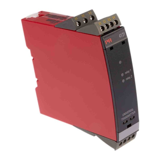
4 1 3 1
U n i v e r s a l
T r i p A m p l i f i e r
N o . 4 1 3 1 V 1 0 3 - I N ( 0 9 3 8 )
F r o m s e r . n o . 0 9 0 3 9 0 0 0 1
S I G N A L S T H E B E S T
Side 1
DK
Page 33
UK
Page 65
FR
Seite 97
DE
Kapitel
Inhaltsverzeichnis

Verwandte Anleitungen für PR electronics 4131


Inhaltszusammenfassung für PR electronics 4131
- Seite 50 Universal-GrenZWertsChalter Preasy 4131 inhaltsverZeiChnis Warnung ................98 Zeichenerklärungen ............99 Sicherheitsregeln ..............99 Konformitätserklärung ............101 Zerlegung des Systems 4000 ..........102 Erweiterte Merkmale ............103 Verwendung ................ 103 Technische Merkmale ............103 PR 4501 Display / Programmierfront ......... 104 Anwendungen ..............
-
Seite 51: Warnung
Pr electronics Gmbh, im erlengrund 26,d-46149 oberhausen, beschädigt werden können. Das Gerät enthält keine internen (tel.: (0) 208 62 53 09-0) oder mit Pr electronics a/s, lerbakken 10, DIP-Schalter oder Programmierbrücken. dk-8410 rønde, dänemark (tel.: +45 86 37 26 77) Kontakt aufnehmen. -
Seite 52: Bedienung Im Normalbetrieb
Wasser leicht angefeuchtet ist. haftUnG In dem Umfang, in welchem die Anweisungen dieses Handbuches nicht genau eingehalten werden, kann der Kunde PR electronics gegenüber keine Ansprüche Rønde, 22. September 2009 Kim Rasmussen geltend machen, welche ansonsten entsprechend der eingegangenen Verkaufs- Unterschrift des Herstellers vereinbarungen existieren können. -
Seite 53: Zerlegung Des Systems 4000
Sensor unverzüglich getauscht werden. technische Merkmale • Wenn das 4131 in Kombination mit der Programmierfront eingesetzt wird, können alle operativen Parameter der entsprechenden Applikation angepasst werden. Das 4131 ist mit elektronischen Hardware-Schaltern ausgestattet und es ist nicht notwendig das Gerät zur Einstellung von DIP-Schaltern zu öffnen. -
Seite 54: Pr 4501 Display / Programmierfront
• Kommunikationsschnittstelle zur Änderung der operativen Parameter im 4131. • Kann von einem 4131 auf das nächste gesteckt werden um die Daten des ersten Messumformers auf den nächsten zu übertragen. • Stationäres Display zur Visualisierung der Prozessdaten und des Status. -
Seite 55: Bestellangaben
EMV Störspannungseinfluss ....... < ±0,5% d. Messsp. 4131 = Universal-Messumformer Erweitere EMV Störfestigkeit: NAMUR NE 21, Kriterium A, Burst ...... < ±1% d. Messsp. 4501 = display / Programmierfront 5910 = CjC-anschlussklemme Hilfsspannungen: 2-Draht-Versorgung (Klemme 44...43) ..25...16 VDC / 0...20 mA elektrische daten Leitungsquerschnitt (max.) ...... -
Seite 56: Visualisierung Im 4501: Sensorfehlererkennung Und
Messbereich ..........0...12 VDC Sensorfehlerprüfung: Programmierbare Messbereiche ....0...1 / 0,2...1 / 0...5 / 1...5 / Gerät: Konfiguration Fühlerfehlererkennung 0...10 und 2...10 VDC R1, ERR.ACT=NONE - R2, ERR.ACT=NONE, Eingangswiderstand ........Nom. 10 MΩ OUT.ERR=NONE. 4131 Sonst:... -
Seite 57: Grenzen Fühlerfehlererkennung
Verbindungsfehler Überprüfe ob Eingangssignal an Eingangskonfiguration passt IN.ER 1) Fehlerniv. im Eingang Überprüfe ob Konfiguration im 4501 Speicher an 4131 passt TY.ER Konfiguration ist nicht 4131 ! Fehleranzeige im Display blinkt einmal pro Sekunde. Der Hilfetext erklärt den Fehler. 1) Um das Gerät zurückzusetzen, muss die Versorgungsspannung kurz unterbrochen werden. -
Seite 58: Blockdiagramm
Dokumentation für das Flussdiagramm. Strom Grundsätzliches Spandnung Bei der Konfiguration des 4131 werden Sie durch alle Parameter geleitet und Potentiometer Sie können die Einstellungen wählen, welche zur Applikation passt. Für jedes Menü existiert ein scrollender Hilfetext welcher automatisch in der 3. Zeile im Display gezeigt wird. - Seite 59 Die Verriegelungsfunktion kann für jeden Relaisausgang separat ausgewählt Relais 1 und 2 an; COM (blinkendes Kugelsymbol) zeigt an, ob das 4501 kor- werden. Beim Kopieren und Übertragen der Konfiguration von einem 4131 zu rekt funktioniert und hoch/runter Pfeile zeigen tendenziell das Eingangssignal an.
-
Seite 60: Manuelle Deaktivierung Der Verriegelungsfunktion (Latch)
Manuelle deaktivierung der verriegelungsfunktion (latch) selbstdiagnose Im Display wird angezeigt, wenn die Relaisausgänge aktiviert und damit ver- Das Gerät führt eine Selbstdiagnose des internen Kreises durch. Die folgenden riegelt sind. Die Hintergrundbeleuchtung blinkt und der scrollende Hilfstext Fehlermeldungen können im Frontdisplay 4501 angezeigt werden. erklärt, wie der Ausgang entriegelt wird. - Seite 61 flUssdiaGraMM Power up Wenn für eine Dauer von 1 Minute keine Taste betätigt wird, kehrt das Schnelleinstellung von Sollwert Display auf den Menüpunkt 1.0 zurück und eventuelle Änderungen in 50.0 und Relaistest der Konfiguration werden nicht gespeichert. RELAY1 1 Sollwert ansteigend 1 Wert erhöhen / nächsten Parameter wählen Txt 57 2 Sollwert fallend...
- Seite 62 SETP HOLD WIND HOLD CLOS CLOS OPEN 3600 3600 N.O. 9999 INCR 250.0 OPEN 3600 3600 NONE 0000 0000 N.C. -1999 DECR NONE 0000 0000 NONE SETP N.O. 50.0 INCR NONE Zum Normal-Zustand 1.0 ERR.ACT ON.DEL OFF.DEL R2.FUNC R2.CONT R2.SETP ACT.DIR R2.HYST ERR.ACT...
-
Seite 63: Verriegelung
flUssdiaGraMM flUssdiaGraMM Verriegelung Erweiterte Einstellungen (ADV.SET) 2.0 Im Untermenü Simulation (SIM) muss 3 DISP betätigt werden um auf den Menüpunkt 1.0 zurückzukehren. SAVE PASS LOAD LANG SAVE SETUP MEMORY Txt 43 Txt 44 DISP 40.0 SETUP CONTRA LIGHT VALVE 5 Rx.LATC ENT.SET Txt 43... -
Seite 64: Scrollender Hilfetext Im Display Zeile 3
Wähle Ni Sensor Typ Relais verriegelt Wähle Pt Sensor Typ Memory Operationen Ausführen Geschlossen [11] Wähle Display Einheit [44] Lade gespeicherte Konfiguration in das 4131 Relaiskontakt Speicher 4131 Konfiguration im 4501 [12] Wähle Dezimalpunkt Position (N.O.) Einstellung LCD Kontrast [13]... -
Seite 65: Grafische Abbildung Der Verriegelungsfunktion „Fenster
Grafische abbildung der verriegelungsfunktion „fenster“ Graphische abbildung der relaisfunktion sollwert Relaiseinheiten Relaiseinheiten Hysterese = 10 Sollwert = 50 Sollwert = 50 Hysterese = 10 Off N.O. On N.O. Off N.O. Off N.O. On N.O. Off N.O. On N.C. Off N.C. On N.C. - Seite 66 Subsidiaries PR electronics A/S tilbyder et bredt program af analoge og digitale France signalbehandlingsmoduler til industriel automation. Programmet PR electronics Sarl Zac du Chêne, Activillage sales@prelectronics.fr består af Isolatorer, Displays, Ex-barrierer, Temperaturtransmittere, 4, allée des Sorbiers tel. +33 (0) 4 72 14 06 07 Universaltransmittere mfl...