Werbung
Quicklinks
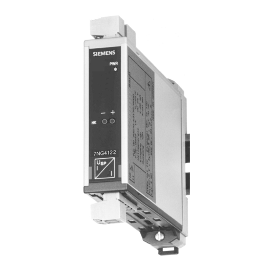
7NG4122
Automation and Drives
Messumformer Speisegerät
D-76181 Karlsruhe
HART
Tel.: +49 721 595-6997
Transmitter Power Supply
HART
Fax +49 721 595-2239
www.feldgeraete.de
www.fielddevices.com
Betriebsanleitung
Operating Instructions
104
84
92
79
79
All manuals and user guides at all-guides.com
Sicherheitshinweise
• Kennzeichnung: II (1) GD [EEx ia] II C
• Vor Inbetriebnahme die Betriebsanleitung lesen.
• Anschluss, Montage und Einstellung nur durch Fach-
personal in Anlehnung an die nationalen/internationa-
len Standards (z.B. VDE 0165) gefolgt von etablierten
Installationsregeln.
• Die eigensicheren Kreise müssen klar getrennt sein und
von anderen getrennt verlegt werden.
• Führt der eigensichere Stromkreis in staubexplosions -
gefährdete Bereiche der Zone 20 bzw. 21, ist sicherzu
stellen, dass Geräte, die an diesem Stromkreis ange-
schlossen werden, die Anforderungen für Kategorie 1D
bzw. 2D erfüllen und entsprechend zertifiziert sind.
• Die auf dem Gerät angegebene Temperaturklasse, die
Explosionsgruppe sowie die besonderen Bedingungen
sind zu beachten.
• Prüfen Sie bei der Sicherheitsbetrachtung, dass die
zulässigen Werte der angeschlossenen Geräte (Ua, Ia,
Po) grösser sind als die Sicherheitsparameter des
Betriebsmittels (Uo, Io, Po).
• Achten Sie darauf, dass die angeschlossenen Kabel
keine grösseren Kapazitäten und Induktivitäten auf-
weisen (Co, Lo, L/R) als die eigensicheren Parameter
des Betriebsmittels.
Insbesondere ist vor der Inbetriebnahme von
•
Geräten mit 230 V Hilfsenergie sicherzustellen, dass
•
der Netzanschluss fachgerecht ausgeführt und der
Schutz gegen elektrischen Schlag sichergestellt ist!
•
das Gerät nach den Bestimmungen der EN 60950
ausserhalb der Stromversorgung spannungslos schalt-
bar ist (z.B. durch den primärseitigen Leitungsschutz)
•
alle Zuleitungen ausreichend abgesichert und
dimensioniert sind!
Vorsicht: Niemals bei anliegender Netzspannung
arbeiten! Lebensgefahr!
Die Geräte sind zum Einbau bestimmt. Nach der Installation
ist der Klemmenbereich abzudecken, um Berührungsschutz
spannungsführender Teile sicherzustellen. Dies ist durch
Einbau im Schaltschrank bzw. Verteilerkasten gegeben.
Bestimmungsgemässe Verwendung
• Richtlinienkonformität Explosionsschutz: Richtlinie 94/9 EG
• Nicht zum Einsatz/Einbau in explosionsgefährdeten
Bereichen
• Das Gerät dient als Schnittstelle zwischen Signalen aus
dem explosionsgefährdeten Bereich (Ex-Bereich) und
dem nicht explosionsgefährdeten Bereich (Nicht-Ex-Bereich)
• Veränderungen am Gerät dürfen nicht vorgenommen
werden!
• Bei elektrischen Betriebsmitteln der Gruppe II kann die
Schutzart IP20 als annehmbar gelten, wenn sie nur für
den Einsatz in trockenen, sauberen und gut überwach
ten Umgebungen vorgesehen sind.
Betrieb
Das Gerät erzeugt eine vollständig galvanisch getrennte
Spannung zur Versorgung von 2-Leiter 4-20mA
Transmittern im Ex-Bereich. Im Ausgang fliesst der glei-
che Strom galvanisch getrennt, um eine Last im sicheren
Bereich zu treiben. Die Schaltung eignet sich zur Übertra-
gung bidirektionaler Kommunikationssignale für HART-
Transmitter. Eine grüne LED signalisiert Betriebsbereit-
schaft.
Installation
Das Gerät befindet sich in einem Kunststoffgehäuse
geeignet zur Montage auf DIN-Schienen nach EN50022.
Der elektrische Anschluss über steckbare Klemmen ist
geeignet für Anschlussquerschnitte bis 2,5 mm
Klemmblöcke können im Betrieb gezogen oder gesteckt
werden, ohne Schaden hervorzurufen. Das Anschlussbild
befindet sich im Datenblatt und auf der Gehäuseseite.
Hilfsenergie: "2 +" und "1 -"
Ausgang : "4 +" ohne 250 Ω Ω Ω Ω Ω oder „6 +" mit 250 Ω Ω Ω Ω Ω und "5 -"
Anschluss 2-Leiter Transmitter : "12 +" und "11 -"
Stellen Sie sicher, dass die Anschlüsse von einander iso-
liert sind und keine unbeabsichtigten Verbindungen erzeu-
gen. Die Gehäuse besitzen einen mechanischen Mindest-
schutz IP20 zur Montage innerhalb von Gebäuden. Die
Montage ausserhalb erfordert einen höheren Schutz (z.B.
IP54 bis IP65) abhängig von der effektiven Anwendung. Die
Geräte sind gegen Schmutz, Staub, sowie extremen me-
chanischen und thermischen Stress zu schützen.
Inbetriebnahme
Vor dem Anlegen der Hilfsenergie ist zu prüfen, ob alle
Anschlussdrähte ordentlich angeschlossen sind, beson-
ders Hilfsenergieanschluss und dessen Polarität, sowie Ein-
gangs- und Ausgangsanschlüsse. Die eigensicheren An-
schlüsse müssen gekennzeichnet sein, vorzugsweise blau
oder durch Markierung.
Legen Sie Hilfsenergie an, die „Power On" - LED muss
leuchten. Jedes Ausgangssignal sollte dem Eingangssignal
entsprechen. Wenn möglich, ändern Sie den Eingangs-
wert und prüfen den entsprechenden Ausgang im Ex-
Bereich.
Safety Information
• Category II (1) GD [EEx ia] II C
• Before setting up read the manual.
• Installation, Mounting and Maintanance only by qualified
personal in accordance to the national/international
standards (e.g. VDE 0165) following the established
installation rules.
• I.S. conductors must be segregated from non I.S. ones.
• If I.S. circuit is passed through zone 20 or 21
hazardous areas, be sure that devices connected to this
circuit fulfil category's 1D e.g. 2D requirements and that
they are certified respectivly.
• The max. operating temperature, the explosion group as
well as special conditions are to be observed.
• In the system analysis check that parameters of connec-
ted field devices (Ua, Ia, Pa) are not exceeded the limits
(Uo, Io, Po) given in the Associated Apparatus parameters.
• Check that adding connecting cables capacitance and
inductance do not exceed the limits (Co, Lo, L/R) given
in the Associated Apparatus parameters.
• Devices with power supply 230 V: Before start-up
ensure that
•
the mains supply has been done professional
and protection against electrical shock is
guaranteed!
•
the device can be disconnected outside the
power supply unit acc. to EN 60950 (e.g. cable
protection on primary side)!
•
all feed lines are sufficiently protected and
dimensioned!
Caution: Never carry out work on live parts!
Danger of fatal injury!
Application is for installation as built-in equipment. After
installation the termination area must be covered to ensure
sufficient protection to envoid electrical shock. Protection is
given by installation of the device in the control cabinet or in
a distributor box.
Intended Purpose
• Conformity Explosion Protection acc. to Directive 94/9/EC
• Not to be located and used in Hazardous Area
• The device is used as an interface for electrical signals
coming from Hazardous and non Hazardous Areas
• Any modification of the device may not be made
• With electrical associated apparatus of group II,
protection class IP20 may be acceptable, if they are
intended for use only in dry, clean and well supervised
environments.
Operation
The device provides fully floating DC supply for energizing
2 wire 4-20 mA transmitters located in Hazardous Area
and repeats the current in a floating circuit to drive a Safe
Area load. The circuit allows bi-directional communication
signal for HART-transmitters, a „POWER ON" green LED
lits when input power is present.
Installation
The device is a powered isolating driver housed in a plastic
enclosure suitable for installation on T35 DIN Rail according
to EN50022. Electrical connection of conductors up to 2,5
2
2
. Die
mm
are accomodated by polarized plug-in removable
srew terminal blocks which can be plugged in/out into a
powered unit without suffering or causing any damage.
On the data sheet and enclosure side a block diagram
identifies all connections.
Connect power supply at terminal "2 +" and "1 -".
Connect output at "4 +" (without 250 Ω)
250 Ω Ω Ω Ω Ω and at "5 -".
Connect 2 wire transmitter at terminal "12 +" and "11 -" .
Make sure that conductors are well isolated from each other
and do not produce any unintentional connection. The
enclosure provides an IP20 minimum degree of mechanical
protection for indoor installation, outdoor installation requires
an additional enclosure with higher degree of protection (i.e.
IP54 to IP65) depending on specific application. Units must
be protected against dirt, dust, extreme mechanical and ther-
mal stress and causal contacts.
Start-Up
Before powering the unit check all wires are properly
connected, particulary supply conductors and their polarity,
input and output wires. Intrinsically Safe conductors and
cable trays must be identified either by color coding,
preferable blue, or by marking. Turn on power, the „power
on" LED must be lit, output signal should be corresponding
to the input from the controller. If possible change the input
value and check the corresponding Hazardous Area output.
Ω)
Ω) or „6 +" with
Ω) Ω)
Werbung

Verwandte Anleitungen für Siemens 7NG4122


Inhaltszusammenfassung für Siemens 7NG4122
- Seite 1 All manuals and user guides at all-guides.com Sicherheitshinweise Safety Information 7NG4122 • Category II (1) GD [EEx ia] II C • Kennzeichnung: II (1) GD [EEx ia] II C • Before setting up read the manual. • Vor Inbetriebnahme die Betriebsanleitung lesen.
- Seite 2 Effektive internal capacitance 3nF wirksame interne Induktivität 50µH Effective internal inductance 50µH Ordering Information Bestellangaben Type Ex-Protect. Power Supply Ordering Code Ex-Schutz Hilfsenergie Bestell-Nr. 7NG4122 ia/ib UC 24 V 7NG4122-1AA10 7NG4122 ia/ib UC 24 V 7NG4122-1AA10 7NG4122 ia/ib AC 230V...