Herunterladen Inhalt Inhalt Diese Seite drucken
Inhaltsverzeichnis

Werbung

Verfügbare Sprachen

Verfügbare Sprachen

INSTALLATIEHANDLEIDING NL/BE
INSTRUCTIONS FOR INSTALLATION GB/IE
INSTALLATIONSVORSCHRIFT DE/AT/BE/LU/CH
INSTRUCTIONS D' INSTALLATION FR/BE/LU/CH
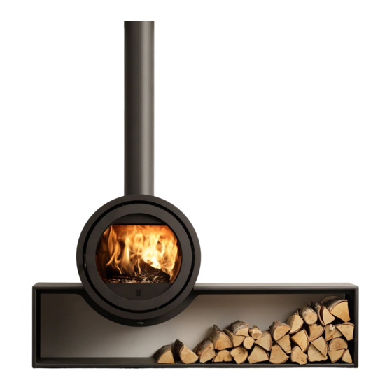
Odin Front
Odin Tunnel
Oval Front
Lees en bewaar dit document zorgvuldig
Please read and retain this document carefully
Dieses Dokument sorgfältig durchlesen und gut aufbewahren
Lisez et conservez soigneusement cette notice

Werbung

Inhaltsverzeichnis
loading

Inhaltszusammenfassung für Dik Geurts Odin Front

  • Seite 1 INSTALLATIEHANDLEIDING NL/BE INSTRUCTIONS FOR INSTALLATION GB/IE INSTALLATIONSVORSCHRIFT DE/AT/BE/LU/CH INSTRUCTIONS D’ INSTALLATION FR/BE/LU/CH Odin Front Odin Tunnel Oval Front Lees en bewaar dit document zorgvuldig Please read and retain this document carefully Dieses Dokument sorgfältig durchlesen und gut aufbewahren Lisez et conservez soigneusement cette notice...
  • Seite 2 Plak hier uw typeplaatje. Adhere your data plate here. Hier das Typenschild einfügen. Collez ici votre plaque signalétique.
  • Seite 3: Inhaltsverzeichnis

    9.5 Ruit(en) 9.5.1 (De)monteren ruit in deur(en) 9.6 Wand- en bodembekleding 9.7 Vlamkeerplaat 9.8 Aanvullende installatie-instructies per uitvoering 9.8.1 Odin Front, Wall / Oval Front, Wall 9.8.1.1 Plaatsen toestel 9.8.1.2 Installatie stucwerk beschermplaat 9.8.2 Odin Fixed, Oval Fixed 9.8.2.1 Plaatsen toestel 9.8.3 Odin Front/Tunnel Plateau, Oval Plateau...
  • Seite 4: Inleiding

    Als fabrikant van haarden ontwikkelt en produceert DRU Verwarming producten volgens de hoogst mogelijke kwaliteits-, prestatie- en veiligheidseisen. Deze houtgestookte Dik Geurts haarden zijn voorzien van een CE-merk, dat alleen gevoerd mag worden voor haarden, die voldoen aan de essentiële eisen uit de Europese Bouwproductenrichtlijn, waaronder eisen voor veiligheid, milieu en energiegebruik.
  • Seite 5: Conformiteitsverklaring

    IN S TA LLA TIE H A N DLE ID IN G 2. Conformiteitsverklaring De ondergetekende, vertegenwoordiger van: Fabrikant: DRU Verwarming BV Postbus 1021 NL-6920 BA Duiven Ratio 8, NL-6921 RW Duiven Verklaart hiermee dat het door DRU uitgebrachte houtgestookte verwarmingstoestel door zijn ontwerp en bouwwijze voldoet aan de essentiële eisen van de Bouwproductenrichtlijn en dat ze geproduceerd en verdeeld wordt volgens de eisen van het Belgisch koninklijk besluit van 12 oktober 2010 tot regeling van de minimale eisen van rendement en emissieniveaus van verontreinigende stoffen voor verwarmingsapparaten voor...
  • Seite 6: Veiligheid

    I N S T A LL A T I E H A N D LE I D I N G 3. VEILIGHEID 3.1 Algemeen • Leest u dit hoofdstuk over veiligheid zorgvuldig door voordat u begint met installatie of onderhoud. !LET OP •...
  • Seite 7: Uitpakken

    IN S TA LLA TIE H A N DLE ID IN G 4. Uitpakken Schenk aandacht aan de onderstaande punten bij het uitpakken: Ø Controleer het toestel met toebehoren op (transport)schade. Ø Installeer nóóit een beschadigde haard! Ø Neem, indien nodig, contact op met uw leverancier. Houd plastic zakken bij kinderen vandaan.
  • Seite 8: Installatie

    I N S T A LL A T I E H A N D LE I D I N G 5. Installatie Lees de handleiding zorgvuldig door voor een goede en veilige installatie van het toestel. 5.1 Voorschriften Ø Installeer de haard volgens de geldende Europese, nationale, lokale en bouwkundige (installatie)voorschriften. Ø...
  • Seite 9: Toestellen Met Ventilator(En)

    IN S TA LLA TIE H A N DLE ID IN G 5.4 Toestellen met ventilator(en) Toestellen, die zijn uitgevoerd met één of meerdere ventilatoren, verwarmen een ruimte sneller en verhogen het comfort. Zodra de ventilator wordt ingeschakeld, is een aangenaam warme luchtstroom voelbaar. De ventilator is op verschillende standen instelbaar.
  • Seite 10: Plaatsen Haard Algemeen

    I N S T A LL A T I E H A N D LE I D I N G 5.7 Plaatsen haard algemeen • Breng zelf geen wijzigingen aan de haard aan. !Let op • Gebruik schone stoffen handschoenen, vermijd vingerafdrukken op de haard en kachelpijpen. •...
  • Seite 11: Vrijstaande / Designhaarden

    IN S TA LLA TIE H A N DLE ID IN G 5.7.1 Vrijstaande / Designhaarden 5.7.1.1 Ombouwen bovenaansluiting naar achteraansluiting haard (indien van toepassing) De haard wordt geleverd met een bovenaansluiting voor het aansluiten op het rookgaskanaal. De bovenaansluiting kan, indien van toepassing, omgebouwd worden naar een achteraansluiting. Volg hiervoor de onderstaande stappen (zie Bijlage 2, afb.
  • Seite 12: Inzethaarden (Bestaande En Nieuwe Situatie)

    I N S T A LL A T I E H A N D LE I D I N G 5.7.2 Inzethaarden (bestaande en nieuwe situatie) 5.7.2.1 In bestaande schouw of boezem Ga voor het plaatsen van een inzethaard in een bestaande schouw of boezem als volgt te werk: Ø...
  • Seite 13 IN S TA LLA TIE H A N DLE ID IN G 5.7.2.2 Bij een nieuwe situatie Ga voor het plaatsen van een inzethaard in een nieuw te bouwen boezem als volgt te werk: Ø Bepaal de plaats van de haard. De afmetingen zijn weergegeven in Bijlage 1, Tabel 2. Ø...
  • Seite 14: Inbouwhaarden

    I N S T A LL A T I E H A N D LE I D I N G 5.7.3 Inbouwhaarden Ø Bepaal de plaats van de kachel. Ø Schuif het inbouwframe (1) in de gewenste positie. Ø Gebruik onbrandbaar en hittebestendig materiaal volgens Eurobrandklasse A1 EN 13501-1 voor de plaat op de vloer, de boezem (inclusief de bovenkant van de boezem), het materiaal ín de boezem en de achterwand waartegen het toestel wordt geplaatst.
  • Seite 15: Afronden Installatie

    IN S TA LLA TIE H A N DLE ID IN G 5.8 Afronden installatie Ø Controleer of er geen gruis, stof of andere materialen in de boezem achterblijven (i.v.m. stank). Ø Gebruik schone stoffen handschoenen en vermijd vingerafdrukken op de haard en kachelpijpen. Ø...
  • Seite 16: Onderhoud

    I N S T A LL A T I E H A N D LE I D I N G 6. Oplevering en onderhoud Ø U dient de gebruiker vertrouwd te maken met de haard. U dient haar/hem onder meer te instrueren over de ingebruikname, het stoken en het onderhoud van de haard.
  • Seite 17: Toestelspecifieke Informatie

    Ø Verwijder de vlamkeerplaat (zie paragraaf 9.7). Ø Draai de moeren van rookgasmond los. De Odin Front/Tunnel, Fixed hangt aan een pijp. Ondersteun het toestel met een heftafeltje of schaarkrikje. Let op! Ø Plaats de restrictieplaat. Zorg er bij het plaatsen voor dat de schotjes van de restrictieplaat altjd naar beneden wijzen.
  • Seite 18: Rookgasafvoer

    I N S T A LL A T I E H A N D LE I D I N G 9.2.3 Rookgasafvoer De rookgasafvoer bij een Odin/Oval heeft een aansluiting met een diameter van 150 mm. De rookgasafvoer kan op twee manieren op de conische afvoerring worden aangesloten: afwaterend en niet-afwaterend.
  • Seite 19: Vervangen Deurafdichting

    IN S TA LLA TIE H A N DLE ID IN G 9.4.1 Vervangen deurafdichting Ga voor het vervangen van de deurafdichting als volgt te werk (zie Bijlage 2, afb. 7): Ø Open de deur. Ø Schuif de deur omhoog en til deze uit. Ø...
  • Seite 20: Wand- En Bodembekleding

    I N S T A LL A T I E H A N D LE I D I N G 9.6 Wand- en bodembekleding Frontuitvoering: De platen bevinden zich op de bodem en tegen de achterwand en zijwanden van het toestel (zie Bijlage 2, afb.
  • Seite 21: Aanvullende Installatie-Instructies Per Uitvoering

    9.8.1 Odin Front, Wall / Oval Front, Wall 9.8.1.1 Plaatsen toestel Dit toestel dient hangend aan een wand gemonteerd te worden. De Odin Front, Wall en Oval Front, Wall mogen uitsluitend aan een verticale wand van solide, onbrandbaar en !LET OP hittebestendig materiaal worden gemonteerd.
  • Seite 22: Odin Fixed, Oval Fixed

    Plaats, indien van toepassing, de restrictieplaat en de vlamkeerplaat. Ø Stel het toestel in de gewenste positie en zet de plafondplaat vast met de 6 stelschroeven. 9.8.3 Odin Front/Tunnel Plateau, Oval Front/Tunnel Plateau 9.8.3.1 Plaatsen toestel • Monteer de eventuele buitenluchtaansluiting voordat het toestel op het plateau wordt gemonteert !Tip (zie paragraaf 9.3).
  • Seite 25 9.5.1 Assembly/disassembly of glass pane in door(s) 9.6 Wall and bottom lining 9.7 Flame baffle plate 9.8 Supplementary installation instructions per appliance 9.8.1 Odin Front, Wall / Oval Front, Wall 9.8.1.1 Placing the appliance 9.8.1.2 Installing the stucco guard plate 9.8.2 Odin Front/Tunnel, Fixed, Oval Fixed 9.8.2.1 Placing the appliance...
  • Seite 26: Introduction

    As a manufacturer of fires, DRU Verwarming develops and produces products according to the highest possible English quality, performance and safety requirements. These woodburning Dik Geurts fires are provided with a CE mark that is only awarded for fires complying with the essential requirements of the European Construction Products Regulation, including requirements made of safety, the environment and energy consumption.
  • Seite 27: Declaration Of Conformity

    IN S TA LLA TION M A N U A L 2. DECLARATION OF CONFORMITY The undersigned, representative of: Manufacturer: DRU Verwarming BV Postbus 1021 NL-6920 BA Duiven Ratio 8, NL-6921 RW Duiven hereby declares that the design and construction of the woodburning heating appliance supplied by DRU satisfies the essential requirements of the Construction Products Regulation and is produced and distributed according to the requirements of the Belgian Royal Decree of 12 October 2010 for the regulation of the minimum requirements of efficiency and emission levels of pollutants for solid fuel heating equipment.
  • Seite 28: Safety

    I N S T A L LA T I ON M A N U A L 3. SAFETY 3.1 General • Carefully read this section about safety before you start installation or maintenance. !CAUTION • Comply with the generally applicable conditions and the precautionary measures/safety instructions in this manual.
  • Seite 29: Unpacking

    IN S TA LLA TION M A N U A L 4. Unpacking Follow the below points below when unpacking: Ø Check the appliance with accessories for (transport) damage. Ø Never install a damaged fire! Ø If necessary contact your supplier. Keep plastic bags away from children.
  • Seite 30: Installation

    I N S T A L LA T I ON M A N U A L 5. Installation Read the manual carefully to ensure the correct and safe installation of the appliance. 5.1 Regulations Ø Install the fire according to the applicable European, national, local and construction (installation) regulations. Ø...
  • Seite 31: Appliances With Fan(S)

    IN S TA LLA TION M A N U A L 5.4 Appliances with fan(s) Appliances that are made with one or more fans will heat a room more quickly and increase comfort. As soon as the fan is switched on you will be able to sense a pleasant, warm air flow. The fan can be set in various positions. The air flow can leave the appliance both at the front and via the convection openings.
  • Seite 32 I N S T A L LA T I ON M A N U A L Any existing chimney must be clear of obstruction and have been swept clean immediately before installation of the stove. If the stove is fitted in place of an open fire then the chimney should be swept one month after installation to clear any soot falls which may have occurred due to the difference in combustion between the stove and the open fire.
  • Seite 33: The Clean Air Act 1993 And Smoke Control Areas

    IN S TA LLA TION M A N U A L Use of fireguard When using the stove in situations where children, aged and/or infirm persons are present a fireguard must be used to prevent accidental contact with the stove. The fireguard should be manufactured in accordance with BS 8423:2002 (Replaces BS 6539).
  • Seite 34: Outside Air Connection

    I N S T A L LA T I ON M A N U A L 5.5.2.2 Exempt appliances Exempt appliances are appliances (ovens, wood burners and stoves) which have been exempted under the Clean Air Act 1993 or Clean Air (Northern Ireland) Order 1981. Appliances which are exempt for use in Smoke Control Areas: https://smokecontrol.defra.gov.uk/appliances.php 5.6 Outside air connection (if applicable) Some fires can be provided with an outside air connection.
  • Seite 35: Free-Standing/Design Fires

    IN S TA LLA TION M A N U A L 5.7.1 Free-standing/design fires 5.7.1.1 Conversion from fire top connection to rear connection (if applicable). The fire is supplied with a top connection for connecting the flue duct. The top connection can be converted to a rear connection. To do this proceed as follows (see Annex 2, Fig.
  • Seite 36: In A New Situation

    I N S T A L LA T I ON M A N U A L Ø Carefully slide the fire into the hole. Make sure that no damage is caused. Ø If applicable connect the convection opening ( see section 5.3 'Convection') with the flexible aluminium pipe and ventilation elements (see section 5.4 'Appliances with fan(s))'.
  • Seite 37: Built-In Fires

    IN S TA LLA TION M A N U A L Ø Use single-walled stainless steel flue pipes or stainless steel double-walled flexible pipes that at least meet the requirements of standard EN 1856-2 T600. Ø The fire may never support the flue. Ø...
  • Seite 38: Maintenance

    I N S T A L LA T I ON M A N U A L 6. Delivery and maintenance Ø You must make the user familiar with the fire. Among other things you must instruct her/him about bringing the fire into use and its burning and maintenance.
  • Seite 39: Appliance-Specific Information

    Remove the flame baffle plate (see section 9.7); Ø Unscrew the nuts of the flue gas mouth. The Odin Front/Tunnel, Fixed is suspended from a pipe. Support the appliance with a lift table or a scissor jack. !Caution Ø Place the restrictor tray.
  • Seite 40: Outdoor Air Connection

    I N S T A L LA T I ON M A N U A L 9.3 Outdoor air connection It is possible to provide the appliance with an outdoor air connection. This outdoor air connection is optional and can be provided as an external kit. This kit can be used for a connection at the bottom of the appliance and is available via your supplier.
  • Seite 41: Adjusting The Door(S)

    IN S TA LLA TION M A N U A L Hang in the door. 9.4.2 Adjusting the door(s) During installation or maintenance, check that the door(s) close(s). If necessary, adjust the door(s). This is the case, if the seal is insufficient (cracks). Ø...
  • Seite 42: Flame Baffle Plate

    9.8.1 Odin Front, Wall / Oval Front, Wall 9.8.1.1 Placing the appliance This appliance must be suspended from a wall. The Odin Front/Tunnel, Wall may only be mounted on a vertical wall made of robust, non combustible and !CAUTION heat-resistant material.
  • Seite 43: Odin Front/Tunnel Plateau, Oval Plateau

    Fit, if applicable, the restriction plate and the baffle plate. Ø Adjust the appliance to the desired position and fix the ceiling plate with the 6 adjusting screws. 9.8.3 Odin Front/Tunnel, Plateau, Oval, Plateau 9.8.3.1 Placing the appliance • Assemble the outdoor air connection (if applicable) before mounting the appliance on the plateau !Tip (see section 9.3).
  • Seite 44 I N S T A L LA T I ON M A N U A L...
  • Seite 47 9.5.1 Einbauen/Ausbauen der Scheibe in der/den Tür(en) 9.6 Wand- und Bodenauskleidung 9.7 Flammenleitwand 9.8 Ergänzende Installationsanweisungen für einzelne Ausführungen 9.8.1 Odin Front, Wall / Oval Front, Wall 9.8.1.1 Aufstellen des Geräts 9.8.1.2 Installation von der Putz-Schutzplatte 9.8.2 Odin Front/Tunnel Fixed / Oval Front/Tunnel 9.8.2.1 Aufstellen des Geräts...
  • Seite 48: Einleitung

    Als Hersteller von Kaminöfen entwickelt und produziert DRU Verwarming Produkte konform den höchstmöglichen Deutsch Qualitäts-, Leistungs- und Sicherheitsanforderungen. Diese mit Holz gefeuerten Dik Geurts-Kaminöfen sind mit einem CE-Zeichen versehen, das nur von Kaminöfen geführt werden darf, die die wesentlichen Anforderungen aus der europäischen Bauprodukterichtlinie erfüllen, unter anderem die Anforderungen in Bezug auf Sicherheit, Umwelt und Energieverbrauch.
  • Seite 49: Konformitätserklärung

    IN S TA LLA TIONS A N LE ITU N G 2. Konformitätserklärung Der Unterzeichner im Auftrag des: Herstellers DRU Verwarming BV Postbus 1021 NL-6920 BA Duiven Ratio 8, NL-6921 RW Duiven erklärt hiermit, dass das von DRU auf den Markt gebrachte, mit Holz gefeuerte Heizgerät durch seinen Entwurf und seine Bauweise den wesentlichen Bestimmungen der Bauprodukterichtlinie entspricht und dass dieses Gerät in Übereinstimmung mit den Anforderungen aus der belgischen königlichen Verordnung (Belgisch koninklijk besluit) vom 12.
  • Seite 50: Sicherheit

    I N S T A L LA T I ON S A N LE I T U N G 3. SICHERHEIT 3.1 Allgemein • Lesen Sie dieses Kapitel über Sicherheit unbedingt sorgfältig durch, bevor Sie mit der Installation oder !ACHTUNG Wartung beginnen.
  • Seite 51: Auspacken

    IN S TA LLA TIONS A N LE ITU N G 4. Auspacken Beachten Sie beim Auspacken die folgenden Punkte: Ø Kontrollieren Sie das Gerät mit dem Zubehör auf (Transport-) Schäden. Ø Installieren Sie niemals einen beschädigten Kamin! Ø Nehmen Sie gegebenenfalls Kontakt mit Ihrem Lieferanten auf. Halten Sie die Kunststoffverpackung von Kindern fern.
  • Seite 52: Installation

    I N S T A L LA T I ON S A N LE I T U N G 5. Installation Lesen Sie die Anleitung sorgfältig durch, um eine gute und sichere Installation des Geräts zu gewährleisten. 5.1 Vorschriften Ø Der Kamin muss in Übereinstimmung mit den geltenden europäischen, nationalen, lokalen und baulichen (Installations-) Vorschriften installiert werden.
  • Seite 53: Geräte Mit Ventilator(En)

    IN S TA LLA TIONS A N LE ITU N G 5.4 Geräte mit Ventilator(en) Geräte, die mit einem oder mehreren Ventilatoren ausgeführt sind, heizen einen Raum schneller und damit erhöht sich der Komfort. Wenn der Ventilator eingeschaltet wird, ist ein angenehm warmer Luftstrom zu spüren. Der Ventilator kann auf verschiedene Stände eingestellt werden.
  • Seite 54: Allgemeine Anweisungen Zum Aufstellen Des Kamins

    I N S T A L LA T I ON S A N LE I T U N G 5.7 Allgemeine Anweisungen zum Aufstellen des Kamins • Bringen Sie selbst keine Änderungen am Kamin an. !Achtung • Ziehen Sie saubere Stoffhandschuhe an, vermeiden Sie Fingerabdrücke auf dem Kamin und den Ofenrohren.
  • Seite 55: Freistehende Kamine / Designkamine

    IN S TA LLA TIONS A N LE ITU N G 5.7.1 Freistehende Kamine / Designkamine 5.7.1.1 Umbauen von einem Anschluss an der Oberseite zu einem Anschluss auf der Rückseite des Kamins (wenn zutreffend) Der Kamin wird mit einem Anschluss für den Rauchgasabzug an der Oberseite geliefert. Der Anschluss an der Oberseite kann gegebenenfalls zu einem Anschluss auf der Rückseite umgebaut werden.
  • Seite 56: Einsatzkamine (Bestehende Und Neue Situation)

    I N S T A L LA T I ON S A N LE I T U N G 5.7.2 Einsatzkamine (bestehende und neue Situation) 5.7.2.1 In einen bestehenden Kaminsims oder Kaminumbau Beim Einbauen eines Einsatzkamins in einen bestehenden Kaminsims oder Kaminumbau gehen Sie wie folgt vor: Ø...
  • Seite 57: Bei Einer Neuen Situation

    IN S TA LLA TIONS A N LE ITU N G 5.7.2.2 Bei einer neuen Situation Beim Einbauen eines Einsatzkamins in einen neu zu bauenden Kaminumbau gehen Sie wie folgt vor: Ø Bestimmen Sie den Aufstellort des Kamins. Die Abmessungen finden Sie in Anlage 1, Tabelle 2. Ø...
  • Seite 58: Einbaukamine

    I N S T A L LA T I ON S A N LE I T U N G 5.7.3 Einbaukamine Ø Bestimmen Sie den Aufstellort des Kamins. Ø Schieben Sie den Einbaurahmen in die gewünschte Position. Ø Verwenden Sie feuerfestes und hitzebeständiges Material konform Eurobrandklasse A1 EN 13501-1 für die Platte auf dem Boden, für den Kaminumbau (inklusive der Oberseite des Kaminumbaus), für das Material im Kaminumbau und für die Rückwand, gegen welche das Gerät gestellt wird.
  • Seite 59: Wartung

    IN S TA LLA TIONS A N LE ITU N G 6. Übergabe und Wartung Ø Sie müssen den Benutzer mit dem Kamin vertraut machen. Sie müssen ihn/sie unter anderem in die Inbetriebnahme, das Heizen und die Wartung des Kamins einweisen. Ø...
  • Seite 60 I N S T A L LA T I ON S A N LE I T U N G...
  • Seite 61: Gerätespezifische Informationen

    Ø Entfernen Sie die Flammenleitwand (siehe Absatz 9.7). Ø Lösen Sie die Muttern der Rauchgasmündung. Das Model Odin Front, Fixed hängt an einem Rohr. Unterstützen Sie das Gerät mit einem Hubtisch oder einem Achtung! Scherenwagenheber. Ø Setzen Sie den Drosselbehälter ein.
  • Seite 62: Außenluftanschluss

    Bei einem entwässernden Anschluss werden andere Anschlussstücke verwendet als bei einem !Achtung nicht-entwässernden Anschluss. Die benötigten Anschlussstücke sind bei Ihrem Händler erhältlich. Die obigen Anweisungen gelten nicht für das Modell Odin Front, Fixed. Bei diesem Typ ist das !Achtung Rauchgasabzugsrohr ein fester Bestandteil des Geräts (siehe Abschnitt 9.8.2).
  • Seite 63: Austauschen Der Türdichtung

    IN S TA LLA TIONS A N LE ITU N G 9.4.1 Austauschen der Türdichtung Gehen Sie beim Austauschen der Türdichtung wie folgt vor (siehe Anlage 2, Abb. 7): Ø Öffnen Sie die Tür. Ø Schieben Sie die Tür nach oben und heben Sie diese heraus. Ø...
  • Seite 64: Wand- Und Bodenauskleidung

    I N S T A L LA T I ON S A N LE I T U N G 9.6 Wand- und Bodenauskleidung Front-Ausführung: Die Platten liegen auf dem Boden und sind gegen die Rückwand und die Seitenwände des Geräts angebracht (siehe Anlage 2, Abb.
  • Seite 65: Ergänzende Installationsanweisungen Für Einzelne Ausführungen

    9.8.1 Odin Front, Wall / Oval Front, Wall 9.8.1.1 Aufstellen des Geräts Dieses Gerät muss hängend an einer Wand montiert werden. Das Modell Odin Front, Wall darf ausschließlich an einer vertikalen Wand aus solidem, feuerfestem und !ACHTUNG hitzebeständigem Material montiert werden.
  • Seite 66: Aufstellen Des Geräts

    I N S T A L LA T I ON S A N LE I T U N G 9.8.2 Odin Fixed / Oval Fixed 9.8.2.1 Aufstellen des Geräts Gehen Sie bei der Installation des Geräts wie folgt vor (siehe Anhang 2, Abb. 17, 18 & 19): Das Gerät darf nur an einer waagerechten, nicht brennbaren und festen Decke montiert werden.
  • Seite 67: Aufstellen Des Geräts

    9.8.3 Odin Front/Tunnel, Plateau / Oval Front, plateau 9.8.3.1 Aufstellen des Geräts • Montieren Sie den eventuellen Außenluftanschluss, bevor Sie das Gerät auf dem Plateau montieren (siehe !Tipp Abschnitt 9.3). • Bei der Installation eines Odin/Oval Front-Geräts muss die Temperaturentwicklung sowohl an der Geräterückseite als auch am Kamin berücksichtigt werden.
  • Seite 69 9.6 Revêtement mural et de sol 9.7 Déflecteur de flammes 9.8 Instructions d’installation complémentaires par appareil 9.8.1 Odin Front, Wall / Oval Front, Wall 9.8.1.1 Mise en place de l'appareil 9.8.1.2 Installation de la plaque de protection du plâtrage 9.8.2 Odin, Fixed / Oval, Fixed 9.8.2.1 Mise en place de l'appareil...
  • Seite 70: Introduction

    En tant que fabricant de poêles, DRU Verwarming développe et fabrique des produits suivant les plus hautes exigences possibles en matière de sécurité, de qualité et de performances. Ces poêles à bois Dik Geurts sont pourvus d'une marque CE, qui peut uniquement être apposée sur des poêles qui satisfont aux exigences essentielles émanant de la directive européenne relative aux produits de construction, dont des exigences en...
  • Seite 71: Déclaration De Conformité

    M A N U E L D'IN S TA LLA T ION 2. Déclaration de conformité Le soussigné, représentant de : Fabricant : DRU Verwarming BV Boîte postale 1021 NL-6920 BA Duiven Ratio 8, NL-6921 RW Duiven déclare par la présente que l'appareil de chauffage au bois commercialisé par DRU est conforme en termes de conception et de fabrication aux exigences essentielles de la directive relative aux produits de construction et qu'il a été...
  • Seite 72: Sécurité

    M A N U E L D ' I N S T A LLA T I ON 3. SÉCURITÉ 3.1 Généralités • Veuillez lire attentivement le présent chapitre relatif à la sécurité avant de commencer l'installation ou !ATTENTION l'entretien de l'appareil. •...
  • Seite 73: Déballage

    M A N U E L D'IN S TA LLA T ION 4. Déballage Soyez attentif aux points suivants durant le déballage : Ø Contrôlez que l'appareil et ses accessoires n’ont pas été endommagés (durant le transport). Ø N'installez jamais un poêle endommagé ! Ø...
  • Seite 74: Installation

    M A N U E L D ' I N S T A LLA T I ON 5. Installation Veuillez lire attentivement le présent manuel pour une installation sûre et exacte de l’appareil. 5.1 Prescriptions Ø Installez le poêle suivant les prescriptions (d'installation) européennes, nationales, locales et architectoniques. Ø...
  • Seite 75: Appareils Avec Ventilateur(S)

    M A N U E L D'IN S TA LLA T ION 5.4 Appareils avec ventilateur(s) Les appareils équipés d'un ou plusieurs ventilateur(s) chauffent une pièce plus rapidement et augmentent le confort. Dès que le ventilateur est actionné, un agréable courant d'air chaud est perceptible. Le ventilateur est réglable sur différentes positions.
  • Seite 76: Mise En Place Du Poêle: Généralités

    M A N U E L D ' I N S T A LLA T I ON 5.7 Mise en place du poêle : généralités • N'apportez vous-même aucune modification au poêle. !Attention • Utilisez des gants en tissu propres, évitez les empreintes de doigts sur le poêle et les conduits du poêle. •...
  • Seite 77: Poêles Design / Isolés

    M A N U E L D'IN S TA LLA T ION 5.7.1 Poêles design / isolés 5.7.1.1 Transformation d'un poêle à raccordement supérieur en un poêle à raccordement arrière (le cas échéant) Le poêle est livré avec un raccordement supérieur à raccorder sur le conduit de cheminée. Le cas échéant, ce raccordement supérieur peut être transformé...
  • Seite 78: Inserts (Situation Existante Et Nouvelle)

    M A N U E L D ' I N S T A LLA T I ON 5.7.2 Inserts (situation existante et nouvelle) 5.7.2.1 Dans une cheminée ou un manteau de cheminée existant(e) Pour la mise en place d'un insert dans une cheminée ou un manteau de cheminée existant(e), procédez comme suit : Ø...
  • Seite 79 M A N U E L D'IN S TA LLA T ION Ø Remettez en place le chapeau de retenue devant la sortie, les plaques de revêtement intérieur dans l’ordre inverse et placez le déflecteur contre la paroi arrière et sur les profils (voir le cas échéant le chapitre 9 'Informations propres à...
  • Seite 80: Foyers À Encastrer

    M A N U E L D ' I N S T A LLA T I ON 5.7.3 Foyers à encastrer Ø Déterminez l'emplacement du foyer. Ø Faites glisser la structure d'encastrement à l'endroit souhaité. Ø Utilisez un matériau ininflammable et résistant à la chaleur suivant la classe de combustibilité A1 EN 13501-1 pour la plaque sur le sol, le manteau de cheminée (y compris la face avant de celui-ci), le matériau dans le manteau et le mur arrière contre lequel l’appareil est placé.
  • Seite 81: Entretien

    M A N U E L D'IN S TA LLA T ION 6. Livraison et entretien Ø Vous devez familiariser l'utilisateur avec le poêle. Vous devez notamment l'instruire sur la mise en service, la combustion et l'entretien du poêle. Ø Lors de la mise en service, indiquez qu' •...
  • Seite 82 M A N U E L D ' I N S T A LLA T I ON...
  • Seite 83: Informations Propres À L'appareil

    Retirez le déflecteur de flammes (voir paragraphe 9.7). Ø Desserrez les écrous de la bouche du conduit des gaz de fumée. Le modèle Odin Front/Tunnel, Fixed est suspendu à un tuyau. Soutenez l’appareil avec une table élévatrice ou !Attention un cric ciseau.
  • Seite 84: Évacuation Des Gaz De Fumées

    Les pièces de raccordement requises sont disponibles auprès de votre fournisseur. Les instructions ci-dessus ne s’appliquent pas pour le modèle Odin Front/Tunnel, Fixed. Sur ce type de poêle, le !Attention tuyau d’évacuation des gaz de fumée fait partie intégrante de l’appareil (voir paragraphe 9.8.2).
  • Seite 85: Remplacement Du Joint D'étanchéité De Porte

    M A N U E L D'IN S TA LLA T ION 9.4.1 Remplacement du joint d'étanchéité de porte Pour remplacer le joint d’étanchéité de porte, procédez comme suit (voir l'Annexe 2, fig. 7) : Ø Ouvrez la porte. Ø Faites glisser la porte vers le haut et sortez-la.
  • Seite 86: Revêtement Mural Et De Sol

    M A N U E L D ' I N S T A LLA T I ON 9.6 Revêtement mural et de sol Modèle frontal : Les plaques se trouvent au fond et contre la paroi arrière et les parois latérales de l’appareil (voir l’Annexe 2, fig. 11).
  • Seite 87: Instructions D'installation Complémentaires Par Appareil

    9.8.1 Odin Front, Wall / Oval Front, Wall 9.8.1.1 Mise en place de l'appareil Cet appareil doit être suspendu à un mur. Le modèle Odin Front, Wall peut exclusivement être suspendu à un mur vertical en matériau solide, !ATTENTION ininflammable et résistant à la chaleur.
  • Seite 88: Odin, Fixed / Oval, Fixed

    Monter, le cas échéant, la plaque de restriction et le déflecteur. Ø Réglez l'appareil dans la position souhaitée et fixez la plaque de plafond avec les 6 vis de réglage. 9.8.3 Odin Front/Tunnel, Plateau / Oval Front, Plateau 9.8.3.1 Mise en place de l'appareil •...
  • Seite 91 Bijlage/Appendix/Anlage/Annexe 1: Tabellen/Tables /Tabellen/Tableaux Tabel/Table/Tabelle/Tableau 1: Meegeleverde onderdelen/Parts included/Lieferumfang/Pièces fournies Onderdeel / Part / Teil / Pièce Aantal / Quantity / Anzahl / Nombre Installatiehandleiding / Installation manual / Installationsanleitung / Manuel d’installation Gebruikershandleiding / User manual / Bedienungsanleitung / Manuel de l’utilisateur Handschoen / Glove / Handschuh / Gant Asschep / Ash scoop /...
  • Seite 94 Bijlage/Appendix/Anlage/Annexe 2: Afbeeldingen/Figures/Abbildungen/Figures 52c/0008-01 52c-0182 52c-0168-01...
  • Seite 95 (3x) 52c-0170 52c-0172-01...
  • Seite 96 52c-0174 52c-0173 (2x) 52c-0179-01 52c-0183-02...
  • Seite 97 52c-0181 52c-0301 52c-0175...
  • Seite 98 52c-0185 52c-313 52c-314...
  • Seite 99 52c-315...
  • Seite 100 DRU, Ratio 8, NL-6921 RW, Name und Anschrift des Herstellers / Nom et adresse du fabricant Duiven, The Netherlands Dik Geurts Odin Front Modelnaam(en) / Model identifier(s) / Modellkennung(en) / Identificateur(s) de modèle Gelijkwaardige modellen / Equivalent models / Äquivalente Modelle / Modèles équivalents EZKA/2017-01/00021-2 Test rapporten / Test reports / Testberichte / Rapports d’essai...
  • Seite 101 Characteristics for exclusive operation with the preferred fuel Symbool Waarde Eenheid Symbool Waarde Eenheid Symbol Value Unit Symbol Value Unit Artikel / Item / Artikel / Objet Artikel / Item / Artikel / Objet Symbol Wert Einheit Symbol Wert Einheit Symbole Valeur Unité...
  • Seite 102 DRU, Ratio 8, NL-6921 RW, Name und Anschrift des Herstellers / Nom et adresse du fabricant Duiven, The Netherlands Dik Geurts Odin Tunnel Modelnaam(en) / Model identifier(s) / Modellkennung(en) / Identificateur(s) de modèle Gelijkwaardige modellen / Equivalent models / Äquivalente Modelle / Modèles équivalents EZKA/2017-01/00021-1 Test rapporten / Test reports / Testberichte / Rapports d’essai...
  • Seite 103 Characteristics for exclusive operation with the preferred fuel Symbool Waarde Eenheid Symbool Waarde Eenheid Symbol Value Unit Symbol Value Unit Artikel / Item / Artikel / Objet Artikel / Item / Artikel / Objet Symbol Wert Einheit Symbol Wert Einheit Symbole Valeur Unité...
  • Seite 104 DRU, Ratio 8, NL-6921 RW, Name und Anschrift des Herstellers / Nom et adresse du fabricant Duiven, The Netherlands Dik Geurts Oval Front Modelnaam(en) / Model identifier(s) / Modellkennung(en) / Identificateur(s) de modèle Gelijkwaardige modellen / Equivalent models / Äquivalente Modelle / Modèles équivalents EZKA/2022-01/00015-1 Test rapporten / Test reports / Testberichte / Rapports d’essai...
  • Seite 105 Characteristics for exclusive operation with the preferred fuel Symbool Waarde Eenheid Symbool Waarde Eenheid Symbol Value Unit Symbol Value Unit Artikel / Item / Artikel / Objet Artikel / Item / Artikel / Objet Symbol Wert Einheit Symbol Wert Einheit Symbole Valeur Unité...
  • Seite 106 Bijlage/Appendix/Anlage/Annexe 3: HETAS...
  • Seite 112 DRU Verwarming B.V. Ratio 8, 6921 RW Duiven Postbus 1021, 6920 BA Duiven Nederland DRU Belgium Kontichsesteenweg 69/1 Unit A-6 2630 Aartselaar Belgium Drugasar Ltd. Deans Road, Swinton Manchester M27 0JH United Kingdom...

Diese Anleitung auch für:

Odin tunnelOval front

Inhaltsverzeichnis