Herunterladen Inhalt Inhalt Diese Seite drucken
Balluff BTL7-V50T-M Serie Betriebsanleitung
Vorschau ausblenden Andere Handbücher für BTL7-V50T-M Serie:
Inhaltsverzeichnis

Werbung

Verfügbare Sprachen
  • DE

Verfügbare Sprachen

  • DEUTSCH, seite 1
BTL7-V50T-M _ _ _ _ -A/B/Y/Z(8)-C003
Betriebsanleitung
deutsch
english
User's guide
français
Notice d'utilisation
italiano
Manuale d'uso
español
Manual de instrucciones

Werbung

Inhaltsverzeichnis
loading

Inhaltszusammenfassung für Balluff BTL7-V50T-M Serie

  • Seite 1 BTL7-V50T-M _ _ _ _ -A/B/Y/Z(8)-C003 Betriebsanleitung deutsch english User’s guide français Notice d’utilisation italiano Manuale d’uso español Manual de instrucciones...
  • Seite 2 www.balluff.com...
  • Seite 3 BTL7-V50T-M _ _ _ _ -A/B/Y/Z(8)-C003 Betriebsanleitung deutsch...
  • Seite 4 www.balluff.com...
  • Seite 5: Inhaltsverzeichnis

    Maximale Abtastfrequenz f Zubehör Positionsgeber Befestigungsmutter Steckverbinder 7.3.1 Versorgungskabel, konfektioniert mit geradem M8-Stecker 7.3.2 Versorgungskabel, konfektioniert mit gewinkeltem M8-Stecker 7.3.3 Datenkabel, konfektioniert mit M12-Stecker 7.3.4 Datenkabel, konfektioniert mit RJ45-Stecker 7.3.5 Datenstecker gerade, frei konfektionierbar 7.3.6 Datenstecker gewinkelt, frei konfektionierbar www.balluff.com deutsch...
  • Seite 6 BTL7-V50T-M _ _ _ _ -A/B/Y/Z(8)-C003 Magnetostriktives Positionsmesssystem – Bauform Stab Typenschlüssel Anhang Umrechnung Längeneinheiten Typenschild deutsch...
  • Seite 7: Benutzerhinweise

    EN 61000-4-8 Die Positionsgeber sind in unterschiedlichen Nähere Informationen zu Richtlinien, Zulas- Bauformen lieferbar und deshalb gesondert zu sungen und Normen sind in der Konformitätser- bestellen. klärung aufgeführt. Zulassungen und Kennzeichnungen Zertifiziert nach Conformance Class A, B und C. www.balluff.com deutsch...
  • Seite 8: Sicherheit

    Industriebereich vorgesehen. Die einwandfreie Funktion Die verwendeten Warnhinweise enthalten verschiedene gemäß den Angaben in den technischen Daten wird nur Signalwörter und sind nach folgendem Schema aufgebaut: mit original Balluff Zubehör zugesichert, die Verwendung SIGNALWORT anderer Komponenten bewirkt Haftungsausschluss. Art und Quelle der Gefahr Das Öffnen des BTL oder eine nichtbestimmungsgemäße...
  • Seite 9: Aufbau Und Funktion

    Positionsgeber: Definiert die zu messende Position auf dem Wellenleiter. Positionsgeber sind in unterschiedlichen Bauformen lieferbar und gesondert zu bestellen (siehe Zubehör auf Seite 15). Der Mindestabstand (L) zwischen den Positionsgebern muss mindestens 65 mm betragen. Bild 3-2: Abstand zwischen den Positionsgebern www.balluff.com deutsch...
  • Seite 10: Funktion

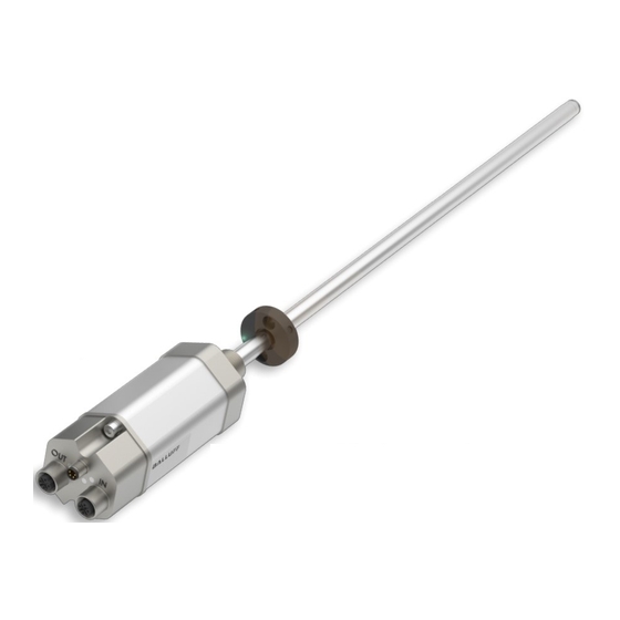
    BTL7-V50T-M _ _ _ _ -A/B/Y/Z(8)-C003 Magnetostriktives Positionsmesssystem – Bauform Stab Aufbau und Funktion (Fortsetzung) Funktion Im BTL befindet sich der Wellenleiter, geschützt durch ein Edelstahlrohr. Entlang des Wellenleiters wird ein Positions- geber bewegt. Dieser Positionsgeber ist mit dem Anlagen- bauteil verbunden, dessen Position bestimmt werden soll. Der Positionsgeber definiert die zu messende Position auf dem Wellenleiter.
  • Seite 11: Led Anzeige

    Konfiguration des Sensors. Sensor befindet sich im zyklischen Datenaustausch. Tab. 3-2: LED 2 3.3.3 LED 3 / LED 4: Link/Activity LED 3/LED 4 Zustand Verbindung Grün Port offen Blinkt Zur Geräteidentifikation vom Master angefordert Port geschlossen Nein Tab. 3-3: LED 3 und LED 4 www.balluff.com deutsch...
  • Seite 12: Einbau Und Anschluss

    BTL7-V50T-M _ _ _ _ -A/B/Y/Z(8)-C003 Magnetostriktives Positionsmesssystem – Bauform Stab Einbau und Anschluss Einbauvarianten Einbau vorbereiten Einbauvariante: Für die Aufnahme des BTL und des Nichtmagnetisierbares Material Positionsgebers empfehlen wir nichtmagnetisierbares Material. nichtmagnetisierbares Material Waagerechte Montage: Bei waagerechter Montage mit Nennlängen > 500 mm ist der Stab abzustützen und gege- benenfalls am Ende anzuschrauben (nur bei Ø 10,2 mm möglich).
  • Seite 13: Btl Einbauen

    Möglich sind z. B. Torlon, Teflon oder Bronze. Gleitelement Distanzring Positionsgeber Bild 4-7: Fixierung Positionsgeber Ein Beispiel für den Einbau des BTL mit einem Stützrohr ist in Bild 4-8 auf Seite 12 dargestellt. Bild 4-5: Beispiel 1, BTL wird mit Gleitelement eingebaut www.balluff.com deutsch...
  • Seite 14: Elektrischer Anschluss

    BTL7-V50T-M _ _ _ _ -A/B/Y/Z(8)-C003 Magnetostriktives Positionsmesssystem – Bauform Stab Einbau und Anschluss (Fortsetzung) BUS IN/OUT (Daten) Positionsgeber (z. B. BTL-P-1028-15R) Adernfarbe Signal YE Gelb WH Weiß OG Orange TX− BU Blau RX− Tab. 4-3: Pinbelegung Steckverbinder ...-C003, BUS IN/OUT Stützrohr aus nichtmagnetisierbarem Material Schirmung und Kabelverlegung Bild 4-8: Beispiel 2, BTL wird mit Stützrohr eingebaut...
  • Seite 15: Inbetriebnahme

    Reparatur durch den Hersteller die korrekten Werte im Nullpunkt und Endpunkt prüfen. Hinweise zum Betrieb – Funktion des BTL und aller damit verbundenen Kom- ponenten regelmäßig überprüfen. – Bei Funktionsstörungen das BTL außer Betrieb neh- men. – Anlage gegen unbefugte Benutzung sichern. www.balluff.com deutsch...
  • Seite 16: Technische Daten

    Zustand) Für UL: Gebrauch in geschlossenen Räumen und bis zu einer Höhe von 2000 m über Meeresspiegel. Einzelbestimmung nach Balluff Werknorm Resonanzfrequenzen ausgenommen Für UL: Das BTL muss extern über einen energiebegrenzten Stromkreis gemäß UL 61010-1 oder eine Stromquelle begrenzter Leistung gemäß...
  • Seite 17 −  4 0…+  6 0 °C Betriebstemperatur BTL-P-1013-4S BTL-P-1028-15R (Sonderzubehör für Applikationen mit Stützrohranwendung): Gewicht ca. 68 g Gehäuse Aluminium 120° BTL-P-1012-4R Ø 4.3 Bild 7-2: Sonderzubehör BTL-P-1028-15R BTL-P-1014-2R Befestigungsmutter – Befestigungsmutter M18×1.5: BTL-A-FK01-E-M18×1.5 – Befestigungsmutter 3/4"-16UNF: BTL-A-FK01-E-3/4"-16UNF Bild 7-1: Einbaumaße Positionsgeber www.balluff.com deutsch...
  • Seite 18: Zubehör

    BTL7-V50T-M _ _ _ _ -A/B/Y/Z(8)-C003 Magnetostriktives Positionsmesssystem – Bauform Stab Zubehör (Fortsetzung) Steckverbinder 7.3.2 Versorgungskabel, konfektioniert mit gewinkeltem M8-Stecker 7.3.1 Versorgungskabel, konfektioniert mit M8x1 geradem M8-Stecker – Steckverbinder gerade bzw. gewinkelt, umspritzt, konfektioniert – Buchse M8, 4-polig 32.2 Ø 9.7 Bild 7-3: Steckerverbinder –...
  • Seite 19: Datenkabel, Konfektioniert Mit M12-Stecker

    Bild 7-7: Steckerverbinder gerade - gerade Bestellcode BCC M414-E834-8G-668-PS54N2-020 BCC0JF0 BCC M414-E834-8G-668-PS54N2-050 BCC0JF2 BCC M414-E834-8G-668-PS54N2-100 BCC0JF3 BCC M414-E834-8G-668-PS54N2-150 BCC0JF4 BCC M414-E834-8G-668-PS54N2-200 BCC0JF5 Beispiele: BCC M414-E834-8G-668-PS54N2-020 = Kabellänge 2 m BCC M414-E834-8G-668-PS54N2-050 = Kabellänge 5 m Bild 7-10: Datenkabel mit Stecker BCC M484-… www.balluff.com deutsch...
  • Seite 20 BTL7-V50T-M _ _ _ _ -A/B/Y/Z(8)-C003 Magnetostriktives Positionsmesssystem – Bauform Stab Typenschlüssel BTL7 - V 5 0 T - M0500 - B - C003 Ethernet-Schnittstelle Spannungsversorgung: 5 = 10…30 V DC Kennliniencharakteristik: 0 = konfigurierbar Ethernet-Schnittstellentyp: T = PROFINET Nennlänge (4-stellig): M0500 = metrische Angabe in mm, Nennlänge 500 mm (M0025…M1016: A8, B8, Y8, Z8) (M0025…M7620: A, B, Y, Z) Stabversion, Befestigung:...
  • Seite 21: Anhang

    1 inch = 25,4 mm inch inch 0,03937008 25,4 0,07874016 50,8 0,11811024 76,2 0,15748031 101,6 0,19685039 0,23622047 152,4 0,27559055 177,8 0,31496063 203,2 0,35433071 228,6 0,393700787 Tab. 9-1: Umrechnungstabelle mm-inch Tab. 9-2: Umrechnungstabelle inch-mm Typenschild Bestellcode Seriennummer Bild 9-1: Typenschild BTL7 (Beispiel) www.balluff.com deutsch...
  • Seite 23 BTL7-V50T-M _ _ _ _ -A/B/Y/Z(8)-C003 User’s Guide english...
  • Seite 24 www.balluff.com...
  • Seite 25 7.3.1 Power cable, preassembled with straight M8 plug 7.3.2 Power cable, preassembled with angled M8 plug 7.3.3 Data cable, preassembled with M12 plug 7.3.4 Data cable, preassembled with RJ45 plug 7.3.5 Straight data plug, freely configurable 7.3.6 Angled data plug, freely configurable www.balluff.com english...
  • Seite 26 BTL7-V50T-M _ _ _ _ -A/B/Y/Z(8)-C003 Magnetostrictive Linear Position Sensor – Rod Style Type code Appendix Converting units of length Part label english...
  • Seite 27: Notes To The User

    The magnets are available in various models More detailed information on the guidelines, and must be ordered separately. approvals, and standards is included in the declaration of conformity. Approvals and markings Certified in accordance with Conformance Class A, B and C. www.balluff.com english...
  • Seite 28: Safety

    Flawless function in accordance with the specifications in are structured as follows: the technical data is ensured only when using original SIGNAL WORD Balluff accessories. Use of any other components will void the warranty. Hazard type and source Opening the BTL or non-approved use are not permitted...
  • Seite 29: Construction And Function

    Magnet: Defines the position to be measured on the waveguide. Magnets are available in various models and must be ordered separately (see Accessories on page 15). The distance (L) between the magnets must be at least 65 mm. Fig. 3-2: Distance between the magnets www.balluff.com english...
  • Seite 30: Function

    BTL7-V50T-M _ _ _ _ -A/B/Y/Z(8)-C003 Magnetostrictive Linear Position Sensor – Rod Style Construction and function (continued) Function The BTL contains the waveguide which is protected by an outer stainless steel tube (rod). A magnet is moved along the waveguide. This magnet is connected to the system part whose position is to be determined.
  • Seite 31: Led Display

    The sensor is involved in cyclic data exchange. Tab. 3-2: LED 2 3.3.3 LED 3 / LED 4: Link/Activity LED 3/LED 4 Status Connection Green Port open Flashing Requested by the master to identify the device Port closed Tab. 3-3: LED 3 and LED 4 www.balluff.com english...
  • Seite 32: Installation And Connection

    BTL7-V50T-M _ _ _ _ -A/B/Y/Z(8)-C003 Magnetostrictive Linear Position Sensor – Rod Style Installation and connection Installation guidelines Preparing for installation Installation note: We recommend using non- Non-magnetizable material magnetizable material to mount the BTL and magnet. Non-magnetizable material Horizontal assembly: For horizontal assembly with nominal lengths > 500 mm, support the rod and tighten it at the end if necessary (only possible with a diameter of 10.2 mm).
  • Seite 33: Installing The Btl

    Slide element Magnets Spacer ring Fig. 4-7: Fixing of magnet An example of how to install the BTL with a supporting rod is shown in Fig. 4-8 on page 12. Fig. 4-5: Example 1, BTL installed with slide element www.balluff.com english...
  • Seite 34: Electrical Connection

    BTL7-V50T-M _ _ _ _ -A/B/Y/Z(8)-C003 Magnetostrictive Linear Position Sensor – Rod Style Installation and connection (continued) BUS IN/OUT (data) Magnets (e.g. BTL-P-1028-15R) Wire color Signal YE yellow WH white OG orange TX− BU blue RX− Tab. 4-3: Pin assignment of ...-C003 connector, BUS IN/OUT Supporting rod made of non-magnetizable material Shielding and cable routing Fig.
  • Seite 35: Startup

    Operating notes – Regularly check function of the BTL and all associated components. – Take the BTL out of operation whenever there is a malfunction. – Secure the system against unauthorized use. www.balluff.com english...
  • Seite 36: Technical Data

    IP67 For UL: Use in enclosed spaces and up to a height of 2000 m above sea level. Individual specifications as per Balluff factory standard Resonant frequencies excluded For UL: The BTL must be externally connected via a limited-energy circuit as defined in UL 61010-1, a low-power source as defined in UL 60950-1, or a class 2 power supply as defined in UL 1310 or UL 1585.
  • Seite 37: Accessories

    BTL-P-1028-15R (special accessories for applications with a supporting rod): Weight Approx. 68 g Housing Aluminum 120° BTL-P-1012-4R Ø 4.3 BTL-P-1014-2R Fig. 7-2: BTL-P-1028-15R special accessories Mounting nut – M18×1.5 mounting nut: BTL-A-FK01-E-M18×1.5 – 3/4"-16UNF mounting nut: BTL-A-FK01-E-3/4"-16UNF Fig. 7-1: Magnet installation dimensions www.balluff.com english...
  • Seite 38: Connector

    BTL7-V50T-M _ _ _ _ -A/B/Y/Z(8)-C003 Magnetostrictive Linear Position Sensor – Rod Style Accessories (continued) Connector 7.3.2 Power cable, preassembled with angled M8 plug 7.3.1 Power cable, preassembled with straight M8 M8x1 plug – Straight or angled connector, molded, preassembled – M8 socket, 4-pin 32.2 Ø...
  • Seite 39: Data Cable, Preassembled With M12 Plug

    Ordering code BCC M414-E834-8G-668-PS54N2-020 BCC0JF0 BCC M414-E834-8G-668-PS54N2-050 BCC0JF2 BCC M414-E834-8G-668-PS54N2-100 BCC0JF3 BCC M414-E834-8G-668-PS54N2-150 BCC0JF4 BCC M414-E834-8G-668-PS54N2-200 BCC0JF5 Examples: BCC M414-E834-8G-668-PS54N2-020 = cable length of 2 m BCC M414-E834-8G-668-PS54N2-050 = cable length of 5 m Fig. 7-10: Data cable with BCC M484-… plug www.balluff.com english...
  • Seite 40 BTL7-V50T-M _ _ _ _ -A/B/Y/Z(8)-C003 Magnetostrictive Linear Position Sensor – Rod Style Type code BTL7 - V 5 0 T - M0500 - B - C003 Ethernet interface Supply voltage: 5 = 10 to 30 V DC Output gradient: 0 = Configurable Ethernet interface type: T = PROFINET Nominal length (4-digit): M0500 = Metric specification in mm, nominal length 500 mm...
  • Seite 41: Converting Units Of Length

    101.6 0.19685039 0.23622047 152.4 0.27559055 177.8 0.31496063 203.2 0.35433071 228.6 0.393700787 Tab. 9-1: Conversion table mm to inches Tab. 9-2: Conversion table inches to mm Part label Order code Type Serial number Fig. 9-1: BTL7 part label (example) www.balluff.com english...
  • Seite 43 BTL7-V50T-M _ _ _ _ -A/B/Y/Z(8)-C003 Notice d’utilisation français...
  • Seite 44 www.balluff.com...
  • Seite 45 7.3.1 Câble d’alimentation, confectionné avec connecteur M8 droit 7.3.2 Câble d’alimentation, confectionné avec connecteur M8 coudé 7.3.3 Câble de données, confectionné avec connecteur M12 7.3.4 Câble de données, confectionné avec connecteur RJ45 7.3.5 Connecteur de données droit, à assembler 7.3.6 Connecteur de données coudé, à assembler www.balluff.com français...
  • Seite 46 BTL7-V50T-M _ _ _ _ -A/B/Y/Z(8)-C003 Système de mesure de position magnétostrictif – Forme à tige Code de type Annexe Conversion unités de longueur Plaque signalétique français...
  • Seite 47: Guide D'utilisation

    être commandés séparément. Degré de EN 61000-4-8 sévérité 4 Homologations et certifications Pour plus d’informations sur les directives, homologations et certifications, se reporter à la déclaration de conformité. Certification selon la classe de conformité A, B et C. www.balluff.com français...
  • Seite 48: Sécurité

    MOT-CLE dans les caractéristiques techniques, n’est garanti qu’avec les accessoires d’origine de Balluff, l’utilisation d’autres Type et source de danger composants entraîne la nullité de la garantie. Conséquences en cas de non-respect du danger Tout démontage du BTL ainsi que toute utilisation non...
  • Seite 49: Structure Et Fonction

    Les capteurs de position peuvent être fournis sous différentes formes et doivent par conséquent être commandés séparément (voir Accessoires, page 15). La distance minimale (L) entre les capteurs de position doit être de 65 mm. Fig. 3-2 : Distance entre les capteurs de position www.balluff.com français...
  • Seite 50: Fonctions

    BTL7-V50T-M _ _ _ _ -A/B/Y/Z(8)-C003 Système de mesure de position magnétostrictif – Forme à tige Structure et fonction (suite) Fonctions Le BTL abrite le guide d’ondes, qui est protégé par un tube en acier inoxydable. Un capteur de position se déplace le long du guide d’ondes. Le capteur de position est relié...
  • Seite 51: Affichage À Led

    Tab. 3-2 : LED 2 3.3.3 LED 3 / LED 4 : link / activity LED 3 / LED 4 Etat Connexion Verte Allumée Port ouvert Clignotante Permet au maître d’identifier l’appareil Eteinte Port fermé Tab. 3-3 : LED 3 et LED 4 www.balluff.com français...
  • Seite 52: Montage Et Raccordement

    BTL7-V50T-M _ _ _ _ -A/B/Y/Z(8)-C003 Système de mesure de position magnétostrictif – Forme à tige Montage et raccordement Variantes de montage Préparation du montage Variante de montage : pour la fixation du BTL et du Matériau non magnétisable capteur de position, nous recommandons l’utilisation de matériaux non magnétisables.
  • Seite 53: Montage Du Btl

    Bague d’écartement Capteur de position Fig. 4-7 : Fixation du capteur de position Un exemple de montage du BTL avec support est représenté sur la figure 4-8, page 12. Fig. 4-5 : Exemple 1, BTL monté avec élément coulissant www.balluff.com français...
  • Seite 54: Raccordement Électrique

    BTL7-V50T-M _ _ _ _ -A/B/Y/Z(8)-C003 Système de mesure de position magnétostrictif – Forme à tige Montage et raccordement (suite) BUS IN / OUT (données) Capteur de position (p. ex. BTL-P-1028-15R) Broche Couleur de fil Signal YE jaune WH blanc OG orange TX− BU bleu RX−...
  • Seite 55: Mise En Service Du Système

    BTL ou réparation par le fabricant. Conseils d’utilisation – Contrôler régulièrement le fonctionnement du BTL et de tous les composants associés. – En cas de dysfonctionnement, mettre le BTL hors service. – Protéger l’installation de toute utilisation non autorisée. www.balluff.com français...
  • Seite 56: Caractéristiques Techniques

    Pour UL : utilisation à l’intérieur et jusqu’à une altitude max. de 2000 m au-dessus du niveau de la mer. Détermination individuelle selon la norme d’usine Balluff. Exception faite des fréquences de résonance Pour UL : le BTL doit être raccordé en externe par un circuit à énergie limitée, ainsi que défini dans la norme UL 61010-1, ou par une source...
  • Seite 57: Accessoires

    Boîtier Aluminium 120° BTL-P-1012-4R Ø 4.3 Fig. 7-2 : Accessoire spécial BTL-P-1028-15R BTL-P-1014-2R Ecrous de fixation – Ecrou de fixation M18×1.5 : BTL-A-FK01-E-M18×1.5 – Ecrou de fixation 3/4"-16UNF : BTL-A-FK01-E-3/4"-16UNF Fig. 7-1 : Cotes de montage des capteurs de position www.balluff.com français...
  • Seite 58: Connecteurs

    BTL7-V50T-M _ _ _ _ -A/B/Y/Z(8)-C003 Système de mesure de position magnétostrictif – Forme à tige Accessoires (suite) Connecteurs 7.3.2 Câble d’alimentation, confectionné avec connecteur M8 coudé 7.3.1 Câble d’alimentation, confectionné avec M8x1 connecteur M8 droit – Connecteur droit ou coudé, extrudé, confectionné – Douille M8, 4 pôles 32.2 Ø...
  • Seite 59: Câble De Données, Confectionné Avec Connecteur M12

    BCC M414-E834-8G-668-PS54N2-020 BCC0JF0 BCC M414-E834-8G-668-PS54N2-050 BCC0JF2 BCC M414-E834-8G-668-PS54N2-100 BCC0JF3 BCC M414-E834-8G-668-PS54N2-150 BCC0JF4 BCC M414-E834-8G-668-PS54N2-200 BCC0JF5 Exemples : BCC M414-E834-8G-668-PS54N2-020 = longueur de Fig. 7-10 : Câble de données avec connecteur BCC M484-… câble 2 m BCC M414-E834-8G-668-PS54N2-050 = longueur de câble 5 m www.balluff.com français...
  • Seite 60 BTL7-V50T-M _ _ _ _ -A/B/Y/Z(8)-C003 Système de mesure de position magnétostrictif – Forme à tige Code de type BTL7 - V 5 0 T - M0500 - B - C003 Interface Ethernet Alimentation électrique : 5 = 10 … 30 V CC Caractéristique des courbes : 0 = configurable Type d’interface Ethernet : T = PROFINET Longueur nominale (4 chiffres) :...
  • Seite 61: Conversion Unités De Longueur

    76,2 0,15748031 101,6 0,19685039 0,23622047 152,4 0,27559055 177,8 0,31496063 203,2 0,35433071 228,6 0,393700787 Tab. 9-1 : Conversion mm/pouce Tab. 9-2 : Conversion pouce/mm Plaque signalétique Symbolisation commerciale Type Numéro de série Fig. 9-1 : Plaque signalétique BTL7 (exemple) www.balluff.com français...
  • Seite 63 BTL7-V50T-M _ _ _ _ -A/B/Y/Z(8)-C003 Manuale d’uso Italiano...
  • Seite 64 www.balluff.com...
  • Seite 65 7.3.2 Cavo di alimentazione, confezionato con connettore M8 ad angolo 16 7.3.3 Cavo dati, confezionato con connettore M12 7.3.4 Cavo dati, confezionato con connettore RJ45 7.3.5 Connettore dati diritto, confezionabile liberamente 7.3.6 Connettore dati ad angolo, confezionabile liberamente www.balluff.com italiano...
  • Seite 66 BTL7-V50T-M _ _ _ _ -A/B/Y/Z(8)-C003 Sensore di posizionamento lineare magnetostrittivo – versione a barra Legenda codici di identificazione Appendice Conversione delle unità di lunghezza Targhetta di identificazione italiano...
  • Seite 67: Avvertenze Per L'utente

    – Campi magnetici ordinati separatamente. EN 61000-4-8 Grado di definizione 4 Autorizzazioni e contrassegni Ulteriori informazioni in merito a direttive, autorizzazioni e norme sono indicate nella dichiarazione di conformità. Certificazione secondo Conformance Class A, B e C. www.balluff.com italiano...
  • Seite 68: Sicurezza

    Il funzionamento corretto secondo le indicazioni fornite nei schema seguente: dati tecnici viene garantito soltanto con accessori originali PAROLA DI SEGNALAZIONE Balluff. L’utilizzo di altri componenti comporta la decadenza della garanzia. Natura e fonte del pericolo L’apertura o l’uso improprio del BTL non sono consentiti e Conseguenze in caso di mancato rispetto dell’avvertenza...
  • Seite 69: Struttura E Funzione

    I datori di posizione sono disponibili in varie tipologie costruttive e devono essere ordinati separatamente (vedere Accessori a pagina 15). La distanza minima (L) tra i datori di posizione deve corrispondere ad almeno 65 mm. Bild 3-2: Distanza tra i datori di posizione www.balluff.com italiano...
  • Seite 70: Funzionamento

    BTL7-V50T-M _ _ _ _ -A/B/Y/Z(8)-C003 Sensore di posizionamento lineare magnetostrittivo – versione a barra Struttura e funzione (continua) Funzionamento Nel BTL si trova la guida d’onda, protetta da un tubo in acciaio inox. Lungo la guida d’onda viene spostato un datore di posizione. Questo datore di posizione è collegato al componente dell’impianto del quale deve essere determinata la posizione.
  • Seite 71: Display Led

    Il sensore si trova in scambio dati ciclico. Tab. 3-2: LED 2 3.3.3 LED 3 / LED 4: Link/Activity LED 3/LED 4 Stato Connessione Verde Acceso Porta aperta Sì Lampeggio Richiesto dal master per Sì l’identificazione dell’apparecchio Spento Porta chiusa Tab. 3-3: LED 3 e LED 4 www.balluff.com italiano...
  • Seite 72: Montaggio E Collegamento

    BTL7-V50T-M _ _ _ _ -A/B/Y/Z(8)-C003 Sensore di posizionamento lineare magnetostrittivo – versione a barra Montaggio e collegamento Varianti di montaggio Preparazione del montaggio Variante di montaggio: per l’installazione del BTL e del Materiale non magnetizzabile datore di posizione si consiglia l’impiego di materiale non magnetizzabile.
  • Seite 73: Montaggio Btl

    Datore di posizione Bild 4-7: Fissaggio del datore di posizione Un esempio per il montaggio del BTL con un tubo di supporto è rappresentato nella figura 4-8 a pagina 12. Bild 4-5: Esempio 1, il BTL viene montato con un elemento scorrevole www.balluff.com italiano...
  • Seite 74: Collegamento Elettrico

    BTL7-V50T-M _ _ _ _ -A/B/Y/Z(8)-C003 Sensore di posizionamento lineare magnetostrittivo – versione a barra Montaggio e collegamento (continua) BUS IN/OUT (dati) Datore di posizione (p. es. BTL-P-1028-15R) Colore filo Segnale YE giallo WH bianco OG arancione TX− BU blu RX− Tab. 4-3: Piedinatura connettore ...-C003, BUS IN/OUT Tubo di supporto in materiale non magnetizzabile Schermatura e posa dei cavi Bild 4-8:...
  • Seite 75: Messa In Funzione Del Sistema

    Avvertenze per il funzionamento – Controllare periodicamente il funzionamento del BTL e di tutti i componenti ad esso collegati. – In caso di anomalie di funzionamento disattivare il BTL. – Proteggere l’impianto da un uso non autorizzato. www.balluff.com italiano...
  • Seite 76: Dati Tecnici

    EN 60068-2-6 3), 4) Per UL: Uso in spazi chiusi e fino a un’altezza di 2000 m sul livello del mare. Grado di protezione IEC 60529 Rilevazione singola secondo la norma interna Balluff Connettore C003 (avvitato) IP67 Frequenze di risonanza escluse Per UL: Il BTL deve essere collegato esternamente mediante un circuito elettrico ad energia limitata in base alla norma UL 61010-1 oppure...
  • Seite 77: Accessori

    Peso ca. 68 g Supporto alluminio 120° BTL-P-1012-4R Ø 4.3 BTL-P-1014-2R Bild 7-2: Accessori speciali BTL-P-1028-15R Dado di fissaggio – Dado di fissaggio M18×1.5: BTL-A-FK01-E-M18×1.5 – Dado di fissaggio 3/4"-16UNF: BTL-A-FK01-E-3/4"-16UNF Bild 7-1: Dimensioni montaggio datore di posizione www.balluff.com italiano...
  • Seite 78: Connettori

    BTL7-V50T-M _ _ _ _ -A/B/Y/Z(8)-C003 Sensore di posizionamento lineare magnetostrittivo – versione a barra Accessori (continua) Connettori 7.3.2 Cavo di alimentazione, confezionato con connettore M8 ad angolo 7.3.1 Cavo di alimentazione, confezionato con M8x1 connettore M8 diritto – Connettore diritto o ad angolo, incorporato, confezionato –...
  • Seite 79: Cavo Dati, Confezionato Con Connettore M12

    Tipo Codice d’ordine BCC M414-E834-8G-668-PS54N2-020 BCC0JF0 BCC M414-E834-8G-668-PS54N2-050 BCC0JF2 BCC M414-E834-8G-668-PS54N2-100 BCC0JF3 BCC M414-E834-8G-668-PS54N2-150 BCC0JF4 BCC M414-E834-8G-668-PS54N2-200 BCC0JF5 Esempi: BCC M414-E834-8G-668-PS54N2-020 = lunghezza cavo 2 m BCC M414-E834-8G-668-PS54N2-050 = lunghezza cavo 5 m Bild 7-10: Cavo dati con connettore BCC M484-… www.balluff.com italiano...
  • Seite 80: Legenda Codici Di Identificazione

    BTL7-V50T-M _ _ _ _ -A/B/Y/Z(8)-C003 Sensore di posizionamento lineare magnetostrittivo – versione a barra Legenda codici di identificazione BTL7 - V 5 0 T - M0500 - B - C003 Interfaccia Ethernet Tensione di alimentazione: 5 = 10…30 V DC Curva caratteristica: 0 = configurabile Tipo interfaccia Ethernet: T = PROFINET Lunghezza nominale (a 4 cifre):...
  • Seite 81: Conversione Delle Unità Di Lunghezza

    0,19685039 0,23622047 152,4 0,27559055 177,8 0,31496063 203,2 0,35433071 228,6 0,393700787 Tab. 9-1: Tabella di conversione mm-pollici Tab. 9-2: Tabella di conversione pollici-mm Targhetta di identificazione Codice d’ordine Tipo Numero di serie Bild 9-1: Targhetta di identificazione BTL7 (esempio) www.balluff.com italiano...
  • Seite 83 BTL7-V50T-M _ _ _ _ -A/B/Y/Z(8)-C003 Manual de instrucciones español...
  • Seite 84 www.balluff.com...
  • Seite 85 7.3.2 Cable de alimentación, confeccionado con conector M8 acodado 16 7.3.3 Cable de datos, confeccionado con conector M12 7.3.4 Cable de datos, confeccionado con conector RJ45 7.3.5 Conector de datos recto, libremente confeccionable 7.3.6 Conector de datos acodado, libremente confeccionable www.balluff.com español...
  • Seite 86 BTL7-V50T-M _ _ _ _ -A/B/Y/Z(8)-C003 Sistema magnetostrictivo de medición de posición – forma constructiva de varilla Código de modelo Anexo Conversión de unidades de longitud Placa de características español...
  • Seite 87: Indicaciones Para El Usuario

    – Campos magnéticos Grado de EN 61000-4-8 severidad 4 Homologaciones e identificaciones En la declaración de conformidad figura más información sobre las directivas, homologaciones y normas. Certificado según la Conformance Class A, B y C. www.balluff.com español...
  • Seite 88: Seguridad

    óptimo según las indicaciones que figuran en los datos de señalización y se estructuran según el siguiente técnicos solo se garantiza con accesorios originales de esquema: Balluff; el uso de otros componentes provoca la PALABRA DE SEÑALIZACIÓN exoneración de responsabilidad. Tipo y fuente de peligro No se permite la apertura del BTL o un uso indebido.
  • Seite 89: Estructura Y Funcionamiento

    (véase Accesorios en la página 15). La distancia mínima (L) entre los sensores de posición debe ser de 65 mm como mínimo. Fig. 3-2: Distancia entre los sensores de posición www.balluff.com español...
  • Seite 90: Funcionamiento

    BTL7-V50T-M _ _ _ _ -A/B/Y/Z(8)-C003 Sistema magnetostrictivo de medición de posición – forma constructiva de varilla Estructura y funcionamiento (continuación) Funcionamiento En el BTL se encuentra el guíaondas, protegido mediante un tubo de acero inoxidable. A lo largo del guíaondas se mueve un sensor de posición. Este sensor de posición está...
  • Seite 91: Indicadores Led

    Tab. 3-2: LED 2 3.3.3 LED 3 / LED 4: Link/Activity LED 3/LED 4 Estado Conexión Verde Puerto abierto Sí Parpadeo Requerido por el maestro Sí para la identificación de los aparatos. Puerto cerrado Tab. 3-3: LED 3 y LED 4 www.balluff.com español...
  • Seite 92: Montaje Y Conexión

    BTL7-V50T-M _ _ _ _ -A/B/Y/Z(8)-C003 Sistema magnetostrictivo de medición de posición – forma constructiva de varilla Montaje y conexión Variantes de montaje Preparación del montaje Variante de montaje: para alojar el BTL y el sensor de Material no imantable posición, recomendamos un material no imantable. Material no imantable Montaje horizontal: en caso de montaje horizontal con longitudes nominales > 500 mm, la varilla debe apoyarse...
  • Seite 93: Montar El Btl

    Fig. 4-7: Fijación del sensor de posición En la figura 4-8 de la página 12 se representa un ejemplo de montaje del BTL con un tubo de apoyo. Fig. 4-5: Ejemplo 1, el BTL se monta con un elemento de deslizamiento www.balluff.com español...
  • Seite 94: Conexión Eléctrica

    BTL7-V50T-M _ _ _ _ -A/B/Y/Z(8)-C003 Sistema magnetostrictivo de medición de posición – forma constructiva de varilla Montaje y conexión (continuación) BUS IN/OUT (datos) Sensor de posición (p. ej. BTL-P-1028-15R) Color del Señal conductor YE amarillo WH blanco OG naranja TX− BU azul RX− Tab.
  • Seite 95: Puesta En Servicio Del Sistema

    Indicaciones sobre el servicio – Compruebe periódicamente el funcionamiento del BTL y todos los componentes relacionados. – Si se producen fallos de funcionamiento, ponga fuera de servicio el BTL. – Asegure la instalación contra cualquier uso no autorizado. www.balluff.com español...
  • Seite 96: Datos Técnicos

    3), 4) Para UL: uso en espacios cerrados y hasta una altura de 2000 m sobre el nivel del mar. Grado de protección según Disposición individual según la norma de fábrica de Balluff IEC 60529 Frecuencias de resonancias excluidas Conector C003 (atornillado)
  • Seite 97: Accesorios

    Aprox. 68 g Carcasa Aluminio BTL-P-1012-4R 120° Ø 4.3 BTL-P-1014-2R Fig. 7-2: Accesorios especiales BTL-P-1028-15R Tuerca de fijación – Tuerca de fijación M18×1.5: BTL-A-FK01-E-M18×1.5 – Tuerca de fijación 3/4"-16UNF: BTL-A-FK01-E-3/4"-16UNF Fig. 7-1: Medidas de montaje de los sensores de posición www.balluff.com español...
  • Seite 98: Conectores

    BTL7-V50T-M _ _ _ _ -A/B/Y/Z(8)-C003 Sistema magnetostrictivo de medición de posición – forma constructiva de varilla Accesorios (continuación) Conectores 7.3.2 Cable de alimentación, confeccionado con conector M8 acodado 7.3.1 Cable de alimentación, confeccionado con M8x1 conector M8 recto – Conector recto o acodado, recubierto, confeccionado –...
  • Seite 99: 7.3.3 Cable De Datos, Confeccionado Con Conector M12

    BCC M414-E834-8G-668-PS54N2-020 BCC0JF0 BCC M414-E834-8G-668-PS54N2-050 BCC0JF2 BCC M414-E834-8G-668-PS54N2-100 BCC0JF3 BCC M414-E834-8G-668-PS54N2-150 BCC0JF4 BCC M414-E834-8G-668-PS54N2-200 BCC0JF5 Ejemplos: BCC M414-E834-8G-668-PS54N2-020 = longitud de cable 2 m BCC M414-E834-8G-668-PS54N2-050 = longitud de cable 5 m Fig. 7-10: Cable de datos con conector BCC M484-… www.balluff.com español...
  • Seite 100: Código De Modelo

    BTL7-V50T-M _ _ _ _ -A/B/Y/Z(8)-C003 Sistema magnetostrictivo de medición de posición – forma constructiva de varilla Código de modelo BTL7 - V 5 0 T - M0500 - B - C003 Interface Ethernet Alimentación de tensión: 5 = 10…30 V DC Características de la curva: 0 = Configurable Tipo de interfaz Ethernet: T = PROFINET...
  • Seite 101: Conversión De Unidades De Longitud

    152,4 0,27559055 177,8 0,31496063 203,2 0,35433071 228,6 0,393700787 Tab. 9-1: Tabla de conversión mm-pulgadas Tab. 9-2: Tabla de conversión pulgadas-mm Placa de características Código de pedido Tipo Número de serie Fig. 9-1: Placa de características del BTL7 (ejemplo) www.balluff.com español...
  • Seite 102 US Service Center CN Service Center Germany Germany China Balluff GmbH Balluff GmbH Balluff Inc. Balluff (Shanghai) trading Co., ltd. Schurwaldstrasse 9 Schurwaldstrasse 9 8125 Holton Drive Room 1006, Pujian Rd. 145. 73765 Neuhausen a.d.F. 73765 Neuhausen a.d.F. Florence, KY 41042 Shanghai, 200127, P.R.

Inhaltsverzeichnis