Anmelden
Hochladen
Anleitungen
Marken
Balluff Anleitungen
Messgeräte
BTL7-V50T-M Serie
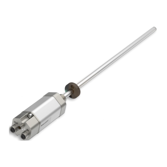
Balluff BTL7-V50T-M Serie Handbücher
Anleitungen und Benutzerhandbücher für Balluff BTL7-V50T-M Serie. Wir haben
4
Balluff BTL7-V50T-M Serie Anleitungen zum kostenlosen PDF-Download zur Verfügung: Betriebsanleitung, Konfigurationsanleitung, Montageanleitung
Balluff BTL7-V50T-M Serie Betriebsanleitung (102 Seiten)
Marke:
Balluff
| Kategorie:
Messgeräte
| Dateigröße: 7.13 MB
Inhaltsverzeichnis
Inhaltsverzeichnis
5
Benutzerhinweise
7
Gültigkeit
7
Verwendete Symbole und Konventionen
7
Lieferumfang
7
Zulassungen und Kennzeichnungen
7
Sicherheit
8
Bestimmungsgemäße Verwendung
8
Vernünftigerweise Vorhersehbare Fehlanwendung
8
Allgemeines zur Sicherheit
8
Bedeutung der Warnhinweise
8
Entsorgung
8
Aufbau und Funktion
9
Aufbau
9
Funktion
9
LED Anzeige
10
LED 2: PROFINET-Status (Duo-LED)
10
LED 3 / LED 4: Link/Activity
10
Verbindung
10
LED 1: BTL-Status
10
Einbau und Anschluss
11
BTL Einbauen
11
Geführte Positionsgeber
11
Freie Positionsgeber
12
Elektrischer Anschluss
13
Steckverbinder BTL7
13
Schirmung und Kabelverlegung
13
Inbetriebnahme
14
System in Betrieb Nehmen
14
Hinweise zum Betrieb
14
Technische Daten
15
Genauigkeit
15
Umgebungsbedingungen
15
Spannungsversorgung (Extern)
15
Ausgang
15
Maße, Gewichte
15
Maximale Abtastfrequenz F
15
Zubehör
16
Geführte Positionsgeber
16
Gelenkstange BTL2-GS10
16
Freie Positionsgeber
17
Steckverbinder
18
Versorgungskabel, Konfektioniert mit Geradem M8-Stecker
18
Versorgungskabel, Konfektioniert mit Gewinkeltem M8-Stecker
18
Datenkabel, Konfektioniert mit M12-Stecker
18
Datenkabel, Konfektioniert mit RJ45-Stecker
18
Datenstecker Gerade, Frei Konfektionierbar
19
Datenstecker Gewinkelt, Frei Konfektionierbar
19
Anhang
21
Umrechnung Längeneinheiten
21
Typenschild
21
Notes to the User
27
Symbols and Conventions
27
Scope of Delivery
27
Approvals and Markings
27
Safety
28
Intended Use
28
Reasonably Foreseeable Misuse
28
General Safety Notes
28
Explanation of the Warnings
28
Disposal
28
Construction and Function
29
Construction
29
Function
29
LED Display
30
LED 1: BTL Status
30
LED 2: PROFINET Status (Dual LED)
30
LED 3/LED 4: Link/Activity
30
Installation and Connection
31
Installing the BTL
31
Captive Magnets
31
Floating Magnets
32
Electrical Connection
33
Connector BTL7
33
Shielding and Cable Routing
33
Startup
34
Starting up the System
34
Operating Notes
34
Technical Data
35
Accuracy
35
Ambient Conditions
35
Supply Voltage (External)
35
Output
35
Dimensions, Weights
35
Maximum Sampling Rate F
35
Accessories
36
Captive Magnets
36
Btl2-Gs10
36
Floating Magnets
37
Connector
38
Power Cable, Preassembled with Straight M8 Plug
38
Power Cable, Preassembled with Angled M8 Plug
38
Data Cable, Preassembled with M12 Plug
38
Data Cable, Preassembled with RJ45 Plug
38
Straight Data Plug, Freely Configurable
39
Angled Data Plug, Freely Configurable
39
Converting Units of Length
41
Part Label
41
Guide D'utilisation
47
Symboles et Conventions Utilisés
47
Fourniture
47
Homologations et Certifications
47
Sécurité
48
Utilisation Conforme aux Prescriptions
48
Mauvais Usage Raisonnablement Prévisible
48
Généralités Sur la Sécurité
48
Signification des Avertissements
48
Elimination
48
Structure et Fonction
49
Structure
49
Fonction
49
Affichage à LED
50
LED 1 : Statut BTL
50
LED 2 : Statut PROFINET (Dual LED)
50
LED 3 / LED 4 : Link / Activity
50
Montage et Raccordement
51
Montage du BTL
51
Capteurs de Position Guidés
51
Capteurs de Position Libres
52
Raccordement Électrique
53
Connecteur BTL7
53
Blindage et Pose des Câbles
53
Mise en Service du Système
54
Conseils D'utilisation
54
Caractéristiques Techniques
55
Précision
55
Conditions Ambiantes 3)
55
Alimentation Électrique (Externe)
55
Sorties
55
Dimensions, Poids
55
Fréquence D'échantillonnage Maximale F
55
Accessoires
56
Capteurs de Position Guidés
56
Tige Articulée BTL2-GS10
56
Capteurs de Position Libres
57
Connecteurs
58
Câble D'alimentation, Confectionné Avec Connecteur M8 Droit
58
Câble D'alimentation, Confectionné Avec Connecteur M8 Coudé
58
Câble de Données, Confectionné Avec Connecteur M12
58
Câble de Données, Confectionné Avec Connecteur RJ45
58
Connecteur de Données Droit, à Assembler
59
Connecteur de Données Coudé, à Assembler
59
Conversion Unités de Longueur
61
Plaque Signalétique
61
Avvertenze Per L'utente
67
Simboli E Segni Utilizzati
67
Fornitura
67
Autorizzazioni E Contrassegni
67
Sicurezza
68
Uso Conforme
68
Utilizzo Improprio Ragionevolmente Prevedibile
68
Informazioni DI Sicurezza Generali
68
Significato Delle Avvertenze
68
Smaltimento
68
Struttura E Funzione
69
Struttura
69
Funzionamento
69
Display LED
70
LED 1: Stato BTL
70
LED 2: Stato PROFINET (LED Duale)
70
LED 3 / LED 4: Link/Activity
70
Montaggio E Collegamento
71
Montaggio BTL
71
Datore DI Posizione Guidato
71
Datore DI Posizione Libero
72
Collegamento Elettrico
73
Connettori BTL7
73
Schermatura E Posa Dei Cavi
73
Messa in Funzione del Sistema
74
Avvertenze Per Il Funzionamento
74
Dati Tecnici
75
Precisione
75
Condizioni Ambientali 3)
75
Tensione DI Alimentazione (Esterna)
75
Uscita
75
Dimensioni, Pesi
75
Frequenza DI Scansione Massima F Max
75
Accessori
76
Datore DI Posizione Guidato
76
Asta DI Comando BTL2-GS10
76
Datore DI Posizione Libero
77
Connettori
78
Cavo DI Alimentazione, Confezionato con Connettore M8 Diritto
78
Cavo DI Alimentazione, Confezionato con Connettore M8 Ad Angolo
78
Cavo Dati, Confezionato con Connettore M12
78
Cavo Dati, Confezionato con Connettore RJ45
78
Connettore Dati Diritto, Confezionabile Liberamente
79
Connettore Dati Ad Angolo, Confezionabile Liberamente
79
Conversione Delle Unità DI Lunghezza
81
Targhetta DI Identificazione
81
Indicaciones para el Usuario
87
Símbolos y Convenciones Utilizados
87
Volumen de Suministro
87
Homologaciones E Identificaciones
87
Seguridad
88
Uso Debido
88
Aplicación Errónea Previsible desde un Punto de Vista Razonable
88
Generalidades sobre la Seguridad
88
Significado de las Advertencias
88
Eliminación de Desechos
88
Estructura y Funcionamiento
89
Estructura
89
Función
89
Indicador LED
90
LED 1: Estado BTL
90
LED 2: Estado de PROFINET (LED Dual)
90
LED 3 / LED 4: Link/Activity
90
Montaje y Conexión
91
Montaje del BTL
91
Sensores de Posición Guiados
91
Sensores de Posición Libres
92
Conexión Eléctrica
93
Conector BTL7
93
Blindaje y Tendido de Cables
93
Puesta en Servicio del Sistema
94
Indicaciones sobre el Servicio
94
Datos Técnicos
95
Precisión
95
Condiciones Ambientales 3)
95
Alimentación de Tensión (Externa)
95
Salida
95
Medidas, Pesos
95
Frecuencia de Exploración Máxima F
95
Accesorios
96
Sensores de Posición Guiados
96
Varilla Articulada BTL2-GS10
96
Sensores de Posición Libres
97
Conectores
98
Cable de Alimentación, Confeccionado con Conector M8 Recto
98
Cable de Alimentación, Confeccionado con Conector M8 Acodado
98
Cable de Datos, Confeccionado con Conector M12
98
Cable de Datos, Confeccionado con Conector RJ45
98
Conector de Datos Recto, Libremente Confeccionable
99
Conector de Datos Acodado, Libremente Confeccionable
99
Código de Modelo
100
Conversión de Unidades de Longitud
101
Placa de Características
101
Werbung
Balluff BTL7-V50T-M Serie Betriebsanleitung (102 Seiten)
Marke:
Balluff
| Kategorie:
Messgeräte
| Dateigröße: 6.98 MB
Inhaltsverzeichnis
Inhaltsverzeichnis
5
Benutzerhinweise
7
Gültigkeit
7
Verwendete Symbole und Konventionen
7
Lieferumfang
7
Zulassungen und Kennzeichnungen
7
Sicherheit
8
Bestimmungsgemäße Verwendung
8
Vernünftigerweise Vorhersehbare Fehlanwendung
8
Allgemeines zur Sicherheit
8
Bedeutung der Warnhinweise
8
Entsorgung
8
Aufbau und Funktion
9
Aufbau
9
Funktion
10
LED Anzeige
11
LED 2: PROFINET-Status (Duo-LED)
11
LED 3 / LED 4: Link/Activity
11
Verbindung
11
LED 1: BTL-Status
11
Einbau und Anschluss
12
Einbauvarianten
12
Einbau Vorbereiten
12
BTL Einbauen
13
Einbauempfehlung für Hydraulikzylinder
13
Elektrischer Anschluss
14
Steckverbinder BTL7
14
Schirmung und Kabelverlegung
14
Inbetriebnahme
15
System in Betrieb Nehmen
15
Hinweise zum Betrieb
15
Technische Daten
16
Genauigkeit
16
Umgebungsbedingungen 2)
16
Spannungsversorgung (Extern)
16
Ausgang
16
Maße, Gewichte
16
Maximale Abtastfrequenz F Max
16
Zubehör
18
Steckverbinder
18
Versorgungskabel, Konfektioniert mit Geradem M8-Stecker
18
Versorgungskabel, Konfektioniert mit Gewinkeltem M8-Stecker
18
Datenkabel, Konfektioniert mit M12-Stecker
19
Datenkabel, Konfektioniert mit RJ45-Stecker
19
Datenstecker Gerade, Frei Konfektionierbar
19
Datenstecker Gewinkelt, Frei Konfektionierbar
19
Anhang
21
Umrechnung Längeneinheiten
21
Typenschild
21
Notes to the User
27
Symbols and Conventions
27
Scope of Delivery
27
Approvals and Markings
27
Safety
28
Intended Use
28
Reasonably Foreseeable Misuse
28
General Safety Notes
28
Explanation of the Warnings
28
Disposal
28
Construction and Function
29
Construction
29
Function
30
LED Display
31
LED 1: BTL Status
31
LED 2: PROFINET Status (Dual LED)
31
LED 3 / LED 4: Link/Activity
31
Installation and Connection
32
Installation Guidelines
32
Preparing for Installation
32
Installing the BTL
33
Installation Recommendation for Hydraulic Cylinders
33
Electrical Connection
34
Connector BTL7
34
Shielding and Cable Routing
34
Startup
35
Starting up the System
35
Operating Notes
35
Technical Data
36
Accuracy
36
Ambient Conditions 2)
36
Supply Voltage (External)
36
Output
36
Dimensions, Weights
36
Maximum Sampling Rate F
36
Accessories
37
Magnets
37
Mounting Nut
37
Connector
38
Power Cable, Preassembled with Straight M8 Plug
38
Power Cable, Preassembled with Angled M8 Plug
38
Data Cable, Preassembled with M12 Plug
39
Data Cable, Preassembled with RJ45 Plug
39
Straight Data Plug, Freely Configurable
39
Angled Data Plug, Freely Configurable
39
Converting Units of Length
41
Part Label
41
Guide D'utilisation
47
Symboles et Conventions Utilisés
47
Fourniture
47
Homologations et Certifications
47
Sécurité
48
Utilisation Conforme aux Prescriptions
48
Mauvais Usage Raisonnablement Prévisible
48
Généralités Sur la Sécurité
48
Signification des Avertissements
48
Elimination
48
Structure et Fonction
49
Structure
49
Fonctions
50
Affichage à LED
51
LED 1 : Statut BTL
51
LED 2 : Statut PROFINET (Dual LED)
51
LED 3 / LED 4 : Link / Activity
51
Montage et Raccordement
52
Variantes de Montage
52
Préparation du Montage
52
Montage du BTL
53
Recommandation de Montage pour Vérin Hydraulique
53
Raccordement Électrique
54
Connecteur BTL7
54
Blindage et Pose des Câbles
54
Mise en Service du Système
55
Conseils D'utilisation
55
Caractéristiques Techniques
56
Précision
56
Conditions Ambiantes 2)
56
Alimentation Électrique (Externe)
56
Sorties
56
Dimensions, Poids
56
Fréquence D'échantillonnage Maximale F
56
Accessoires
57
Capteurs de Position
57
Ecrous de Fixation
57
Connecteurs
58
Câble D'alimentation, Confectionné Avec Connecteur M8 Droit
58
Câble D'alimentation, Confectionné Avec Connecteur M8 Coudé
58
Câble de Données, Confectionné Avec Connecteur M12
59
Câble de Données, Confectionné Avec Connecteur RJ45
59
Connecteur de Données Droit, à Assembler
59
Connecteur de Données Coudé, à Assembler
59
Conversion Unités de Longueur
61
Plaque Signalétique
61
Avvertenze Per L'utente
67
Simboli E Segni Utilizzati
67
Fornitura
67
Autorizzazioni E Contrassegni
67
Sicurezza
68
Uso Conforme
68
Utilizzo Improprio Ragionevolmente Prevedibile
68
Informazioni DI Sicurezza Generali
68
Significato Delle Avvertenze
68
Smaltimento
68
Struttura E Funzione
69
Struttura
69
Funzionamento
70
Display LED
71
LED 1: Stato BTL
71
LED 2: Stato PROFINET (LED Duale)
71
LED 3 / LED 4: Link/Activity
71
Montaggio E Collegamento
72
Varianti DI Montaggio
72
Preparazione del Montaggio
72
Montaggio BTL
73
Suggerimento DI Montaggio Per Cilindro Idraulico
73
Collegamento Elettrico
74
Connettori BTL7
74
Schermatura E Posa Dei Cavi
74
Messa in Funzione del Sistema
75
Avvertenze Per Il Funzionamento
75
Dati Tecnici
76
Precisione
76
Condizioni Ambientali 2)
76
Tensione DI Alimentazione (Esterna)
76
Uscita
76
Dimensioni, Pesi
76
Frequenza DI Scansione Massima F
76
Accessori
77
Datore DI Posizione
77
Dado DI Fissaggio
77
Connettori
78
Cavo DI Alimentazione, Confezionato con Connettore M8 Diritto
78
Cavo DI Alimentazione, Confezionato con Connettore M8 Ad Angolo
78
Cavo Dati, Confezionato con Connettore M12
79
Cavo Dati, Confezionato con Connettore RJ45
79
Connettore Dati Diritto, Confezionabile Liberamente
79
Connettore Dati Ad Angolo, Confezionabile Liberamente
79
Legenda Codici DI Identificazione
80
Conversione Delle Unità DI Lunghezza
81
Targhetta DI Identificazione
81
Indicaciones para el Usuario
87
Símbolos y Convenciones Utilizados
87
Volumen de Suministro
87
Homologaciones E Identificaciones
87
Seguridad
88
Uso Debido
88
Aplicación Errónea Previsible desde un Punto de Vista Razonable
88
Generalidades sobre la Seguridad
88
Significado de las Advertencias
88
Eliminación de Desechos
88
Estructura y Funcionamiento
89
Estructura
89
Funcionamiento
90
Indicadores LED
91
LED 1: Estado BTL
91
LED 2: Estado de PROFINET (LED Dual)
91
LED 3 / LED 4: Link/Activity
91
Montaje y Conexión
92
Variantes de Montaje
92
Preparación del Montaje
92
Montar el BTL
93
Recomendación de Montaje para Cilindros Hidráulicos
93
Conexión Eléctrica
94
Conector BTL7
94
Blindaje y Tendido de Cables
94
Puesta en Servicio del Sistema
95
Indicaciones sobre el Servicio
95
Datos Técnicos
96
Precisión
96
Condiciones Ambientales 2)
96
Alimentación de Tensión (Externa)
96
Salida
96
Medidas, Pesos
96
Frecuencia de Exploración Máxima F
96
Accesorios
97
Sensor de Posición
97
Tuerca de Fijación
97
Conectores
98
Cable de Alimentación, Confeccionado con Conector M8 Recto
98
Cable de Alimentación, Confeccionado con Conector M8 Acodado
98
7.3.3 Cable de Datos, Confeccionado con Conector M12
99
7.3.4 Cable de Datos, Confeccionado con Conector RJ45
99
Conector de Datos Recto, Libremente Confeccionable
99
Conector de Datos Acodado, Libremente Confeccionable
99
Código de Modelo
100
Conversión de Unidades de Longitud
101
Placa de Características
101
Balluff BTL7-V50T-M Serie Konfigurationsanleitung (50 Seiten)
Marke:
Balluff
| Kategorie:
Messgeräte
| Dateigröße: 12.17 MB
Inhaltsverzeichnis
Deutsch
5
Inhaltsverzeichnis
5
Gültigkeit
6
Marken
6
Systemeigenschaften
7
Einrichten des Systems unter TIA
8
Verwendete Fachbegriffe und Abkürzungen
6
Verwendete Symbole und Konventionen
6
Zu dieser Anleitung
6
Inbetriebnahme auf Basis eines Eigenen Projekts
8
Hardwarekonfiguration
8
Installation des Funktionsbausteins IM TIA Portal V15
10
Konfigurieren der Sensorlänge des Systems
15
Beschreibung des Signals Blockdbmagnets
18
Maximale Verfahrgeschwindigkeit und Speicherbedarf
18
Initialisierung des Systems
19
Erneute Initialisierung (Parameter Reinit)
19
Fehlerrücksetzung (Parameter Errorsreset)
19
Vollständige Initialisierung (Parameter Fullinit)
19
Verwendung der SCADA-Software
20
Fehlerdiagnose und Fehlerbehebung
22
Struktur der Fehlerverarbeitungsdaten (Ausgänge Errorspresented und Errorscollected)
22
Systemmodus (Ausgang Workingmode)
22
Systemstatus (Ausgang Status)
22
Mögliche Fehler und Maßnahmen zur Fehlerbehebung
23
Configuration Guide
27
English
29
About this Guide
30
Symbols and Conventions
30
Trademarks
30
System Features
31
Setting up the System under TIA
32
Used Technical Terms and Abbreviations
30
Startup on the Basis of Your Own Project
32
Hardware Configuration
32
Installation of the Function Block in TIA Portal V15
34
Configure Sensor Length of System
39
Description of the Blockdbmagnets Signal
42
Maximum Movement Speed and Memory Requirements
42
Initialization of the System
43
Error Reset (Errorsreset Parameter)
43
Full Initialization (Fullinit Parameter)
43
Re-Initialization (Reinit Parameter)
43
Using the SCADA Software
44
Error Diagnosis and Troubleshooting
46
Structure of Error Processing Data
46
System Mode (Workingmode Output)
46
System Status (Status Output)
46
Possible Errors and Troubleshooting Measures
47
Werbung
Balluff BTL7-V50T-M Serie Montageanleitung (6 Seiten)
Magnetostriktives Positionsmesssystem
Marke:
Balluff
| Kategorie:
Messgeräte
| Dateigröße: 1.13 MB
Werbung
Verwandte Produkte
Balluff BTL7-P511-Mxxxx-B8-NEX-S32/KA series
Balluff BTL7-E50x-Mxxxx-TB2 Serie
Balluff BTL7-A50x-Mxxxx-TB3 Serie
Balluff BTL7-C50x-Mxxxx-TB3 Serie
Balluff BTL7-A50x-Mxxxx-TZ2 Serie
Balluff BTL7-C50x-Mxxxx-TZ2 Serie
Balluff BTL7-C50x-Mxxxx-TZ3 Serie
Balluff BTL7-A50x-Mxxxx-TT2 Serie
Balluff BTL7-C50x-Mxxxx-TT3 Serie
Balluff BTL7-P511-Mxxxx-Y Serie
Balluff Kategorien
Sensoren
Messgeräte
Module
Netzwerkhardware
Industrielle Ausrüstung
Weitere Balluff Anleitungen
Anmelden
Anmelden
ODER
Mit Facebook anmelden
Mit Google anmelden
Anleitung hochladen
Von PC hochladen
Von URL hochladen