Inhaltsverzeichnis
Werbung
Verfügbare Sprachen
Verfügbare Sprachen
Quicklinks
Werbung
Kapitel
Inhaltsverzeichnis

Verwandte Anleitungen für Chauvin Arnoux C.A 41


Inhaltszusammenfassung für Chauvin Arnoux C.A 41
- Seite 1 All manuals and user guides at all-guides.com FR - Notice de fonctionnement GB - User’s manual DE - Bedienungsanleitung C.A 41 Mesureur de champ électrique large bande Electric field meter wide band Breitbandmessgerät fürelektrische feldstärken...
-
Seite 2: Précautions D'emploi
Afin de maintenir l’appareil dans sa classe de précision et pour obtenir une utilisation optimale, il est déconseillé de laisser le C.A 41 exposé en permanence à des champs supérieurs à 300 V/m ou 100 A/m. Avant d’effectuer une mesure, s’assurer dès la mise en marche de l’appareil que le symbole de décharge... -
Seite 3: Inhaltsverzeichnis
8. PROCÉDURE D’EMPLOI .......................19 9. MAINTENANCE ........................23 9.1. Changement de pile ....................23 9.2. Nettoyage ........................23 10. GARANTIE ...........................23 11. POUR COMMANDER ......................23 Dans la composition du champ-mètre C.A 41, la sonde polarisée EF1 est remplacée par la Sonde Isotrope EF2A. - Seite 4 All manuals and user guides at all-guides.com Afficheur Display Geräteanzeige...
-
Seite 5: Description
Remarques : sous le boîtier se situe la trappe à piles et un insert au pas de 1/4 de pouce UNC (pas «KODAK») pour fixation du C.A 41 sur un support type pied d’appareil photo. 1.2. AFFICHEUR Fonction alarme en service, Seuil alarme franchi, Affichage de l’autonomie restante en % de la capacité,... -
Seite 6: Présentation
Ces techniques modernes sont employées dans pratiquement tous les types d’appareillages industriels ce qui les rend particulièrement sensibles aux parasites et aux perturbations électromagnétiques. Le C.A 41, fabriqué par CHAUVIN ARNOUX, permet de mesurer ces niveaux de perturbations. Les mesures sont de deux types : Mesure d’ambiance (susceptibilité) -
Seite 7: Utilisation
All manuals and user guides at all-guides.com 3. UTILISATION Le commutateur rotatif commande la mise en marche du C.A 41 et permet de sélectionner la mesure avec ou sans alarme. Il dispose de 3 positions : OFF, V/m et V/m (AL). -
Seite 8: Fonctionnement
All manuals and user guides at all-guides.com 4. FONCTIONNEMENT Le C.A 41 possède 4 touches qui permettent d’accéder à des fonctions spécifiques d’enregistrement, de filtrage ou de maintien de valeur de mesure. Chaque appui sur une touche déclenche un bip sonore à 2 kHz pendant 65 ms. Dans tous les cas, le temps de réponse à... -
Seite 9: Maintien De La Valeur Numérique À L'affichage
All manuals and user guides at all-guides.com Remarques : Pendant la lecture des mémoires MIN, MAX et AVG, l’enregistrement de nouvelles valeurs minimales, maximales et moyennes sont prises en compte. Lorsque les symboles RECORD et SMOOTH sont affichés, on enregistre les valeurs lissées (MIN, MAX et AVG) avec une constante de mesure de 4 secondes. - Seite 10 All manuals and user guides at all-guides.com Quelle que soit la position d’affichage: - une pression sur HOLD libère l’enregistrement sans réinitialiser les mémoires. - une pression sur MIN MAX pendant plus de 2 secondes annule la fonction enregistrement. Remarque : En mesure normale (sans enregistrement, donc pas de symbole RECORD) si, après avoir appuyé...
-
Seite 11: Mesure «Crête
La fonction PEAK permet d’effectuer des mesures avec une vitesse d’acquisition de 1 ms pour des mesures crête. Le filtre 50 Hz de réjection des champs BF est inhibé. Le C.A 41 devient sensible aux alimentations des appareils électriques, passages de câbles secteur, ... -
Seite 12: Sortie Analogique
All manuals and user guides at all-guides.com La commande de cette fonction est réalisée par un interrupteur couplé à un potentiomètre monotour (4) de l’appareil. Le potentiomètre permet le réglage du volume sonore en fonction du niveau de champ et de la profondeur de modulation. - Seite 13 All manuals and user guides at all-guides.com - En mesure normale et en mesure lissée (SMOOTH), la constante de filtrage est 400 ms. - En mesure crête (PEAK), la constante de filtrage est beaucoup plus réduite : 1 ms Ceci permet la visualisation de signaux de modulation d’amplitude superposés au signal HF (voir exemple ci-dessous) Exemple : visualisation sur oscilloscope de signaux de modulation GSM.
-
Seite 14: Mémo De Fonctionnement
All manuals and user guides at all-guides.com 5. MÉMO DE FONCTIONNEMENT ① L e HOLD peut être effectué dans tous les modes de fonctionnement. Dans le mode enregistrement ①’ l’acquisition des Min, Max et Moyennes est suspendue (symbole «PAUSE»). ② L e SMOOTH peut être effectué en mode enregistrement. Dans ce cas toutes les valeurs sont lissées (symbole «SMOOTH»). -
Seite 15: Sondes De Mesure
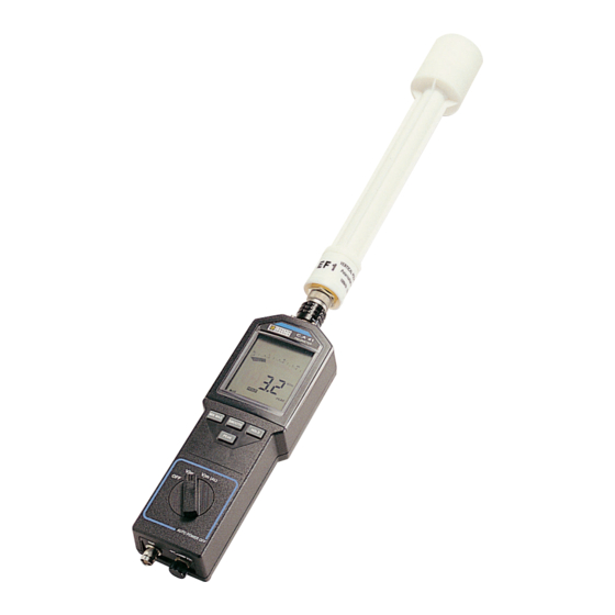
Le signal continu, issu de la détection est transmis à I’appareil de mesure par une ligne résistive permettant à I’ensemble une transparence maximale ne perturbant pas le champ électrique dans lequel I’appareil et son antenne sont plongés. La sonde EF1 livrée avec le C.A 41 est du type dipôle. La mesure est anisotropique ; la réception se fait dans la seule polarisation verticale. -
Seite 16: Caractéristiques
All manuals and user guides at all-guides.com 7. CARACTÉRISTIQUES 7.1. CARACTÉRISTIQUES ÉLECTRIQUES Domaine de mesure spécifié Étendue de de mesure 0,1 V/m à 200 V/m Résolution 0,1 V/m Précision 0,5 dB Temps d’échantillonnage 250 µs Temps de mesure numérique 400 ms Temps de mesure analogique 100 ms Stabilité... - Seite 17 All manuals and user guides at all-guides.com Variations dans le domaine d’utilisation Grandeur Grandeurs d’influence Limite du domaine Variation MAX influencée 0,3 % / °C Température ambiante de 0 à 50°C toutes grandeurs de la lecture ± 0,5 V/m par 10 °C de 10 à...
-
Seite 18: Caractéristiques Mécaniques
- Résistance aux secousses : 100 secousses de 10 g dans les 3 axes (CEI 68-2-29). Dimensions et masse - C.A 41 (sans capteur) : 212 x 72 x 37 mm - 350 g - Sonde de mesure (EF1 / EF2) : longueur : 300 mm - diamètre : 50 mm... -
Seite 19: Procédure D'emploi
All manuals and user guides at all-guides.com 8. PROCÉDURE D’EMPLOI „ Raccorder la sonde de mesure sur le C.A 41 (sonde EF1 ou EF2). La connexion s’effectue par la prise multicontact push pull (1) située en haut de l’appareil. Positionner la sonde dans l’axe du boîtier, „... - Seite 20 All manuals and user guides at all-guides.com Choisir le mode de fonctionnement désiré (cf. chapitre «FONCTIONNEMENT»). „ Selon le cas, effectuer une mesure de rayonnement d’une source perturbatrice ou d’environnement „ d’un appareil perturbé. Pour cela, déplacer la sonde EF1 selon les 3 axes perpendiculaires de l’espace (cf. chapitre „...
- Seite 21 All manuals and user guides at all-guides.com Lire sur l’afficheur la valeur en V/m du champ mesuré; se référer au tableau ci-dessous selon „ les normes CEI 801-3 et CEI 1000-4-3 définissant les niveaux de sévérité de compatibilité électromagnétique. Compatibilité électromagnétique Niveau de sévérité...
- Seite 22 All manuals and user guides at all-guides.com Remarques : A) Si le champ est discontinu (c’est à dire que l’affichage varie sans modifier la position de la sonde) l’utilisation des fonctions SMOOTH et PEAK seront particulièrement intéressantes : - SMOOTH pour lire une valeur moyenne plus représentative du champ global. - PEAK pour repérer des crêtes dont certaines peuvent dépasser le niveau maximal souhaité.
-
Seite 23: Maintenance
11. POUR COMMANDER C.A 41 FIELDMETER ......................P01167001B Composé du boîtier C.A 41 et de la sonde de mesure (Sonde EF2A isotrope). Sont fournis avec l’appareil : 1 jeu de 5 étiquettes adhésives, mode d’emploi simplifiés (5 langues), à coller au dos de l’appareil, „... -
Seite 24: Safety Precautions
In order to keep the instrument in its accuracy class and to obtain optimum use, we advise against leaving the C.A 41 permanently exposed to fields higher than 300 V/m or 100 A/m. Before making a measurement, as soon as the instrument is switched on, check that the low battery symbol is not shown on the display. - Seite 25 8. OPERATING PROCEDURE ......................41 9. MAINTENANCE ........................... 45 9.1. Changing the battery ......................45 9.2. Cleaning ........................... 45 10. WARRANTY ..........................45 11. TO ORDER ..........................45 In the composition of Field-meter C.A 41, polarized probe EF1 is replaced by Isotropic Probe EF2A.
- Seite 26 All manuals and user guides at all-guides.com Afficheur Display Geräteanzeige...
-
Seite 27: Description
- buzzer OFF SMOOTH button - measurement filtering. Notes : Under the case is the battery compartment and a 1/4” UNC lug («KODAK» size) for mounting the C.A 41 on a photographic type support. 1.2. DISPLAY Alarm function ON, Alarm threshold crossed,... -
Seite 28: Presentation
ON, and consequently its class of electromagnetic compatibility in accordance with the applicable standard. The C.A 41 is a small portable instrument that measures the electric field present in the atmosphere surrounding its measurement probe. This probe consists of an aerial combined with a high frequency detector. The wide passband of this unit enables the measurement of electrical fields from 0.1 V/m to 200 V/m for frequencies between... -
Seite 29: Use
All manuals and user guides at all-guides.com 3. USE The rotary switch controls switching ON the C.A 41 and measurement with or without alarm. It has three positions: OFF, V/m and V/m (AL). 3.1. ON/OFF FUNCTION The OFF position of the rotary switch mechanically cuts off the power supply of the instrument. turning the switch to one of the two ON positions (V/m (AL) or V/m) applies the battery voltage to the circuits of the instrument, for a duration of 10 minutes. -
Seite 30: Operation
All manuals and user guides at all-guides.com 4. OPERATION The C.A 41 has four buttons whiwh provide access to specific functions for recording, filtering or holding the measurement value. Each press on a button sets off a beep at 2 kHz for 65 ms. In all cases, the response time for one press is less than 50 ms. -
Seite 31: Hold The Digital Value On The Display
All manuals and user guides at all-guides.com Notes : During reading of the MIN, MAX and AVG memories, the recording of new minimum, maximum and average values is taken into account. When the RECORD and SMOOTH symbols are displayed,the smoothed values are recorded (MIN, MAX and AVG) with a measurement constant of 4 seconds. - Seite 32 All manuals and user guides at all-guides.com Whatever the position of the display: - one press on HOLD stops the recording without reinitialising the memories. - one press on MIN MAX for more than 2 seconds cancels the record function. Note: In normal measurement (without recording, so without RECORD symbol) if, after having pressed HOLD, the user starts recording by pressing the MIN, MAX button and if the readout ofthe contents of the MIN or MAX or AVG memories is needed during this HOLD, the display will show three lines ---.
-
Seite 33: Peak Measurement
The PEAK function allows the user to take measurements with an acquisition speed of 1 ms for peak measurements. The 50 Hz filter for the rejection of low frequency fields is switched OFF. The C.A 41 becomes sensitive to the power supplies of electrical equipment, to mains cable runs, ... -
Seite 34: Analogue Output
All manuals and user guides at all-guides.com 4.7. ANALOGUE OUTPUT The analogue output makes it possible to record data on a plotter, graphic recorder ... with a minimum impedance of 100kΩ. An analogue amplifier adapts the voltage output from the sensor to obtain a proportional DC signal in accordance with a pseudo-quadratic law law. - Seite 35 All manuals and user guides at all-guides.com...
-
Seite 36: Memo On Operation
All manuals and user guides at all-guides.com 5. MEMO ON OPERATION ① HOLD can be used on all operating modes. In record mode ①’ the acquisition of Min, Max and Avg is paused (“PAUSE” symbol). ② SMOOTH can be used in record mode. In this case all the values are smoothed (“SMOOTH» symbol). ③ Similarly PEAK can be used in record mode. -
Seite 37: Measurement Probes
The EF1 probe supplied with the C.A 41 is of the dual pole type. -
Seite 38: Specifications
All manuals and user guides at all-guides.com 7. SPECIFICATIONS 7.1. ELECTRICAL SPECIFICATIONS Specified measurement range Measurement extent 0.1 V/m to 200 V/m Resolution 0.1 V/m Accuracy 0.5 dB Sampling time 250 µs Digital measurement time 400 ms Analogue measurement time 100 ms Stability 0.2 dB... - Seite 39 All manuals and user guides at all-guides.com Variations in the operating range Magnitude Distortion magnitude Limit of range MAX variation distorted 0.3 % / °C Ambiente temperature 0 to 50°C all magnitudes of the reading ± 0.5 V/m per 10 °C 10 to 90 % Humidity all magnitudes...
-
Seite 40: Mechanical Specifications
- Bump resistance: 100 bumps of 10 g in the 3 axes (IEC 68-2-29). Dimensions and weight - C.A 41 (without sensor): 212 x 72 x 37 mm - 350 g - Measurement probe (EF1 / EF2): length: 300 mm... -
Seite 41: Operating Procedure
All manuals and user guides at all-guides.com 8. OPERATING PROCEDURE „ Connect the measurement probe to the C.A 41 (probe EF1 or EF2). The connection is made through the multicontact push-pull socket (1) located at the top of the instrument. - Seite 42 All manuals and user guides at all-guides.com Choose the required operating mode (cf. chapter “OPERATION”). „ As applicable, measure the radiation from a source of disturbance or the environment of a „ disturbed instrument (B). To do this, move the EF1 probe along the 3 perpendicular spatial axes (cf. chapter “MEASUREMENT „...
-
Seite 43: Electromagnetic Compatibility
All manuals and user guides at all-guides.com Read on the display the value in V/m of the field measured. Refer to the table below in accordance „ with standards IEC 801-3 and IEC 1000-4-3 defining the levels of severity of electromagnetic compatibility. - Seite 44 All manuals and user guides at all-guides.com Remarks: A) If the field is fluctuating (i.e. the display varies without changes in the position of the probe) the use of the SMOOTH and PEAK functions will be particularly useful: - SMOOTH to read an average value which is more representative of the global field. - PEAK to identify the peaks, some of which may exceed the maximum level that is wanted.
-
Seite 45: Maintenance
11. TO ORDER C.A 41 FIELDMETER ......................P01167001B Consisting of the C.A 41 unit and the measurement probe (Isotropic probe EF2A). Supplied with the instrument: 1set of 5 ahesive labels, simplified User instructions (5 languages), to stick to the back of the „... -
Seite 46: Sicherheitsvorkehrungen
All manuals and user guides at all-guides.com VOR INBETRIEBNAHME DES GERÄTES UNBEDINGT DIE BETRIEBSANLEITUNG LESEN! ACHTUNG, GEFAHR! Sobald dieses Gefahrenzeichen irgendwo erscheint, ist der Benutzer verpflichtet, die Anleitung zu Rate zu ziehen. ACHTUNG! Gefahr eines elektrischen Stromschlags. Mit diesem Symbol gekennzeichnete Teile stehen möglicherweise unter Gefahrenspannung! Das Gerät ist durch eine doppelte Isolation geschützt. - Seite 47 7.1. Elektrische charakteristiken ...................60 7.2. Mechanische charakteristiken ..................62 8. INBETRIEBNAHME DES GERÄTS ..................63 9. WARTUNG ..........................67 9.1. Batterlewechsel ......................67 9.2. Reinigung ........................67 10. GEWÄHRLEISTUNG ......................67 11. BESTELLANGABEN ......................67 Im Aufbau des Auffangene-Meßinstruments C.A 41, wird polarisierte Prüfspitze EF1 durch isotrope Prüfspitze EF2A ersetzt.
- Seite 48 All manuals and user guides at all-guides.com Afficheur Display Geräteanzeige...
-
Seite 49: Beschreibung
Taste SMOOTH - Glättung der Meßwerte Anmerkung: Unter dem Gehäuse befinden sich das Batteriefach und ein 1/4-Zoll Gewinde («KODAK- Gewinde») für die Befestigung des C.A 41 auf einem Fotostativo. 1.2. GERÄTEANZEIGE Alarmfunktion eingeschaltet, Alarmschwelle überschritten, Anzeige der verbleibenden Betriebsdauer in % der Batteriekapazität,... -
Seite 50: Allgemeine Informationen Zum Gerät
Gerät verursacht wird und somit welcher elektromagnetischen Verträglichkeitsklasse es laut geltender Norm angehört. Beim C.A 41 handelt es sich um ein kleines tragbares Gerät, das die Stärke des elektrischen Feldes in der Umgebung seiner Meßsonde mißt. -
Seite 51: Anwendung
All manuals and user guides at all-guides.com 3. ANWENDUNG Das C.A 41 wird anhand des Drehschalters eingeschaltet und auf Messung mit oder ohne Alarm umgeschaltet. Der Drehschalter hat drei Schaltpositionen: OFF, V/m und V/m (AL). 3.1. EIN- UND AUSSCHALTEN Die Schaltposition OFF des Drehschalters unterbricht mechanisch die Stromversorgung des Geräts. Das Drehen des Schalters auf eine der beiden Einschaltpositionen (V/m (AL) oder V/m) setzt die Schaltkreise des Geräts unter Strom und das Gerät läuft für eine Dauer von 10 Minuten. -
Seite 52: Betrieb Des Gerätes
All manuals and user guides at all-guides.com 4. BETRIEB DES GERÄTES Das Meßgerät C.A 41 besitzt 4 Tasten, die den Zugang zu den Sonderfunktionen Meßwertspeicherung, glättung oder Halten des letzten Meßwertes ermöglichen. Jede Betätigung einer Taste löst ein akustisches Signal mit einer Dauer von 65 ms und einer Frequenz von 2 kHz aus. -
Seite 53: Messwertspeicher
All manuals and user guides at all-guides.com Anmerkungen: Während des Abrufens der Speicherinhalte MIN, MAX und AVG wird die Aufzeichnung weiterer Mindest-, Höchst- und Mittelwerte berücksichtigt. Wenn die Symbole RECORD und SMOOTH angezeigt werden, werden die geglätteten Meßwerte (MIN, MAX und AVG) mit einer Meßkonstante von 4 Sekunden aufgezeichnet. Desgleichen werden, wenn die Symbole RECORD und PEAK angezeigt werden, die Spitzenwerte mit einer Meßkonstante von 1 Sekunde aufgezeichnet. -
Seite 54: Messwertglättung
All manuals and user guides at all-guides.com Angezeigter Wert Angezeigte Symbole ▼ Speicher HOLD HOLD RECORD-PAUSE MIN MAX Speicher MAX RECORD-PAUSE MIN MAX Speicher MIN RECORD-PAUSE MIN MAX Speicher AVG RECORD-PAUSE MIN MAX laufende Messung RECORD-PAUSE MIN MAX Gleichgültig welcher Meßwert gerade angezeigt wird: - durch Betätigen der Taste HOLD die Meßwertaufzeichnung freigegeben, ohne Reinitialisierung der Speicherinhalte. -
Seite 55: Spitzenwertmessung
All manuals and user guides at all-guides.com 4.4. SPITZENWERTMESSUNG Die Funktion PEAK ermöglicht die Durchführung von Messungen mit einer Erfassungszeit von 1ms für Spitzenwertmessungen. Der 50 Hz-Selektivfilter für NF-Felder wird unterdrückt. Das Meßgerät spricht an auf die Stromversorgung elektrischer Geräte, Netzkabel usw.an. Ein erster Druck auf die Taste PEAK schaltet die Funktion ein, und auf der Anzeige erscheint das Symbol PEAK. -
Seite 56: Akustische Demodulation
All manuals and user guides at all-guides.com 4.6. AKUSTISCHE DEMODULATION Anhand der Demodulationsfunktion können Sie sich anhand des eingebauten Lautsprechers eine eventuell vorhandene Amplitudenmodulation des HF-Signals anhören. Diese Modulationsfeststellung ist begrenzt auf hörbare Frequenzen zwischen 500 Hz und 5 kHz. Das beste Ergebnis wird erzielt bei gemessenen Feldern zwischen 5 V/m und 30 V/m mit einer Modulationstiefe von mindestens 50%. - Seite 57 All manuals and user guides at all-guides.com - Bei der normalen Meßwerterfassung und bei der Meßwertglättung (SMOOTH), beträgt die Filterkonstante 400 ms. - Bei der Spitzenwertmessung (PEAK) ist die Filterkonstante viel kürzer: 1 ms. Dies ermöglicht die Anzeige von Amplitudenmodulationssignalen, die das HF-Signal überlagern (siehe Beispiel unten) Beispiel : Anzeige der GSM-Modulationssignale auf dem Oszilloskop.
-
Seite 58: Zusammenfassung Der Funktionen
All manuals and user guides at all-guides.com 5. ZUSAMMENFASSUNG DER FUNKTIONEN Anzeige der laufenden ▼ ① "HOLD" Meβwertspeicher HOLD Messung in V/m ▼ HOLD (Meßzeit : 400 ms) ▼ "SMOOTH" Anzeige des geglätteten Meßwerts SMOOTH Gerät im ② (Zeit der digitalen Messung: 4s) Normal-betrieb ▼... -
Seite 59: Messonden
Signaltransparenz gewährleistet ist, die das elektrische Feld nicht stört, in dem sich Meßgerät und Antenne befinden. Die Sonde EF1, die zusammen mit dem C.A 41 geliefert wird, ist eine Dipolsonde. Die Messung ist anisotropisch ; der Signalempfang erfolgt allein in vertikaler Polarisation. -
Seite 60: Technische Daten
All manuals and user guides at all-guides.com 7. TECHNISCHE DATEN 7.1. ELEKTRISCHE CHARAKTERISTIKEN Angegebener Meßbereich MEβBEREICH 0,1 V/m bis 200 V/m AUFLÖSUNG 0,1 V/m GENAUIGKEIT 0,5 dB DAUER DER MEßWERTWERFASSUNG 250 µs DIGITALE MEßZEIT 400 ms ANALOGE MEßZEIT 100 ms STABILITÄT 0,2 dB Referenzbedingungen... - Seite 61 All manuals and user guides at all-guides.com Veränderungen Anwendungsbereich Maximale Einflußflugröße Grenzen Beinflußte Größen Veränderung 0,3 % / °C der Anzeige Umgebungstemperatur 0 bis 50°C alle ± 1%/°C des Meßbereiches 10 bis 90 % ohne Feuchtigkeit alle < 0,1 V/m Kondensation Stromversorgung 7,5 bis 11 V alle...
-
Seite 62: Mechanische Charakteristiken
- Widerstandsfähigkeit gegen Erschütterungen: 100 Erschütterungen mit 10 G in den 3 Ebenen (IEC 68-2-29). Abmessungen und Gewicht - C.A 41 (ohne Sonde): 212 x 72 x 37 mm - 350 g - Meßsonde (EF1 / EF2): Länge: 300 mm... -
Seite 63: Inbetriebnahme Des Geräts
All manuals and user guides at all-guides.com 8. INBETRIEBNAHME DES GERÄTS „ Schlieβen Sie die Meβsonde an das C.A 41 an (Sonde EF1 oder EF2). Der Anschluβ erfolgt „ anhand des Steckverbinders (1) auf der Oberseite des Geräts. Halten Sie die Meβsonde in gleicher Richtung als das Gerät. - Seite 64 All manuals and user guides at all-guides.com Wählen Sie die gewünschte Betriebsart (siehe Kapitel «BETRIEB DES GERÄTES»). „ Führen Sie je nach Fall eine Messung der Strahlung einer Störquelle oder der Empfindlichkeit „ eines gestörten Gerätes durch (B). Zu diesem Zweck drehen Sie die Sonde EF1 in die drei Raumebenen (siehe Kapitel „...
-
Seite 65: Elektromagnetische Kompatibilität
All manuals and user guides at all-guides.com Lesen Sie auf der Anzeige den Wert des gemessen Feldes in V/m ab. Hinsichtlich der Stufen der „ elektromagnetischen Verträglichkeit ist auf die nachstehende Tabelle Bezug zu nehmen, die in Übereinstimmung mit den Normen IEC 801-3 und IEC 1000-4-3 erstellt worden ist. Elektromagnetische Kompatibilität Härteklasse Maximaler Wert des elektromagnetischen Feldes... - Seite 66 All manuals and user guides at all-guides.com Anmerkungen: A) Wenn das Feld unstetig ist (d.h. die Anzeige verändert sich, ohne Veränderung der Position der Meßsonde), ist die Verwendung der Funktionen SMOOTH und PEAK besonders interessant: - SMOOTH, um den repräsentativsten Mittelwert des Gesamtfeldes festzustellen. PEAK, um die Spitzenwerte festzustellen, von denen einige das gewünschte Höchstniveau überschreiten können.
-
Seite 67: Wartung
11. BESTELLANGABEN C.A 41 FELDSTÄRKENMESSER ..................P01167001B Bestehend aus dem Meßgerät C.A 41 mit der dazugehörigen Meßsonde (isotrope Prüfspitze EF2A). Zusammen mit dem Gerät geliefert werden: 1 Satz, von 5 selbstklebenden Etiketten mit vereinfachten Bedienungsanleitungen (in 5 Sprachen), „... - Seite 68 All manuals and user guides at all-guides.com FRANCE INTERNATIONAL Chauvin Arnoux Group Chauvin Arnoux Group 190, rue Championnet Tél : +33 1 44 85 44 38 75876 PARIS Cedex 18 Fax : +33 1 46 27 95 69 Tél : +33 1 44 85 44 85...