
Verwandte Anleitungen für Chauvin Arnoux C.A 43


Inhaltszusammenfassung für Chauvin Arnoux C.A 43
- Seite 1 FR - Notice de fonctionnement GB - User’s manual DE - Bedienungsanleitung C.A 43 Mesureur de champ large bande Wide band field meter Breitbandiger feldstärkenmesser...
-
Seite 2: Précautions D'emploi
„ Avant d’effectuer une mesure, s’assurer dès la mise en marche du C.A 43 que le symbole de décharge de la pile (35) n’apparaît pas sur l’afficheur. Dans l’affirmative, procéder au changement de la pile. -
Seite 3: Inhaltsverzeichnis
SOMMAIRE 1. DESCRIPTION ..........5 11. INTERROGATION À DISTANCE ....26 1.1. Boîtier ..........5 11.1 Interrogation de la mesure ....27 1.2. Afficheur ...........6 11.2 Interrogation de l’état de l’appareil 27 2. PRÉSENTATION .........7 11.3 Interrogation de la mémoire 2.1 Généralités ........7 mesure ...........28 2.2 Etiquettes mode d’emploi ....7 11.4 Interrogation de la mémoire 3. -
Seite 5: Description
1. DESCRIPTION 1.1. BOÎTIER Commande de démodulation sonore Connecteur optique Commutateur rotatif 4 positions Touche PRGM - Programmation - Initialisation de la mémoire programme Touche MEM - Mémorisation de la mesure - Affichage de l’adresse mémoire - Affichage de la capacité mémoire restante - Initialisation de la mémoire mesure ... -
Seite 6: Afficheur
1.2. AFFICHEUR Mode programmation en service Demande d’impression effectuée. Horloge Cession de mémorisation automatique Cadencement d’impression automatique Emission ou réception sortie numérique en cours Affichage numérique de capacité pile, horloge, ∆t ou durée du scanning Echelle logarithmique Affichage analogique par bargraph 35 segments Pointe de flèche signalant le dépassement de fin d’échelle Unité... -
Seite 7: Présentation
équipement en fonctionnement et par conséquent sa classe de compatibilité électromagnétique selon la norme en vigueur. Appareil portatif, de petites dimensions, le C.A 43 mesure le champ électrique présent dans l’atmosphère environnant sa sonde de mesure. Cette sonde est constituée par une antenne associée à un détecteur haute fréquence. La large bande passante de cet ensemble permet la mesure des champs électriques de 0,1 V/m à... -
Seite 8: Utilisation
3. UTILISATION Votre champmètre se compose d’un boîtier et d’une sonde. Pour raccorder celle-ci, il suffit de la positionner dans l’axe du boîtier, tourner la sonde jusqu’au détrompage (point dur) et l’enfoncer. Le verrouillage s’effectue en tirant à fond vers le boîtier, la bague noire de la sonde (prise multicontacts push-pull). N’essayez jamais de tourner la sonde lorsque celle-ci est encliquetée sur le boîtier, vous risqueriez d’endommager le capteur et ses connexions. -
Seite 9: Fonctions Spéciales
4. FONCTIONS SPÉCIALES MISE MARCHE PERMANENTE Après 10 minutes de fonctionnement sans manipulation de touche ou du commutateur rotatif ou sans interrogation de la sortie numérique, un système d’économie pile met en sommeil l’appareil. Cet arrêt automatique est précédé par l’émission d’un bip sonore et par le clignotement de l’afficheur numérique pendant une minute. -
Seite 10: Affichage De L'heure Courante
Ces «bip» sonores, s’ils vous paraissent trop bruyants, peuvent être supprimés; Pour cela, appuyez simultanément sur MIN MAX à la mise en marche par le commutateur rotatif. La disparition à l’écran du symbole indique que le «bi» sonore est bien désactivé. Cette désactivation du «bip» sonore sera concervée même après arrêt de l’appareil (commutateur en position OFF). -
Seite 11: Effacement De La Mémoire Programme
<groupe 1> <groupe 2> <groupe 3> Le groupe 1 contient 4 caractères alignés sur la gauche, indiquant les fonctions programmées. Elles sont données dans l’ordre suivant : LO AL : Pour le seuil bas HI AL : Pour le seuil haut SCAN : Pour le nombre de minutes du Scanning (affichage HH MM) ∆t... -
Seite 12: Effacement De La Mémoire Mesure
EFFACEMENT DE LA MÉMOIRE MESURE Pour initialiser la mémoire mesure, appuyez simultanément sur MEM à la mise en marche par le commutateur rotatif et maintenez votre pression jusqu’à l’effacement. Le symbole MEM s’allume, le message Init s’affiche en fixe (en haut à droite) pendant 3 secondes et le nombre d’adresses disponibles apparaît sur l’afficheur numérique. -
Seite 13: Blocage De L'affichage Numérique
La fonction PEAK permet d’effectuer des mesures avec une vitesse d’acquisition de 1 ms pour des mesures crête. Le filtre 50 Hz de réjection des champs BF est inhibé. Le C.A 43 devient sensible aux alimentations des appareils électriques, passages de câbles secteur, ... - Seite 14 Valeur MAX De même, une mesure supérieure à la valeur contenue dans le registre MAX entraîne sa mise à jour. A chaque modification du contenu du registre MAX, un «bip» est émis. Valeur MOYENNE (AVG) Initialement, la valeur moyenne correspond à la valeur affichée au premier appui sur MIN MAX.
-
Seite 15: Marche / Arrêt Des Alarmes
Une nouvelle pression sur HOLD libère l’enregistrement des MIN, MAX et AVG : - Les symboles HOLD et PAUSE s’éteignent - L’afficheur numérique indique la mesure en cours ou le contenu des registres MIN, MAX ou AVG en relecture. - L’appareil est à nouveau en mode MIN, MAX et AVG mais les registres n’ont pas été réinitialisés et ils contiennent les valeurs MIN, MAX et AVG présentes avant le HOLD. - Seite 16 Signal sonore : La durée minimale de fonctionnement du buzzer sur une alarme est de 400 ms même lorsque celle-ci a lieu sur une valeur crête de durée inférieure. Lorsqu’un seuil est franchi, un hystérésis de 1 % est appliqué sur la consigne de celui-ci, ce qui oblige la mesure a repasser en dessous de cette dernière valeur pour quitter l’alarme.
-
Seite 17: Fonctionnement
1920 est affiché. MÉMORISATION AUTOMATIQUE Le champmètre C.A 43 peut être utilisé en surveillance de site. Avec une session ∆t programmée de 1 minute à 24 heures, les valeurs min, max et moyenne correspondant à chaque session sont mémorisées automatiquement. -
Seite 18: Relecture Mémoire Mesure
A chaque mémorisation le symbole MEM clignote une fois et un signal sonore est émis. Si la mémoire mesure est pleine (1920 adresses), le symbole MEM clignote et la mémorisation cesse. L’arrêt du mode mémorisation automatique est obtenu par un appui sur MIN MAX de plus de deux secondes. - Seite 19 La première adresse relue contient les paramètres de la valeur AVG (l’affichage de l’horloge ▼ contient la durée du ∆t programmée). L’appui sur fait s’afficher les paramètres de la mesure MAX (l’horloge indique l’heure où a eu lieu ce maximum). La troisième adresse relue en décrémentation contient les paramètres de la mesure MIN (l’horloge indique l’heure où...
-
Seite 20: Mode Impression
Si aucun seuil n’est programmé, la touche ALARM est inopérante et il faut passer en mode Programmation pour éventuellement fixer une valeur de seuil. A chaque affichage de dépassement de seuil, le symbole de franchissement de seuil d’alarme précise le type d’alarme en action. Lorsque l’on quitte le mode relecture mémoire, il n’est pas nécessaire de remonter à... -
Seite 21: Impression Automatique
Pour interrompre l’impression en cours de la mémoire mesure, il suffit d’appuyer une seconde fois sur PRINT. 7.2 IMPRESSION AUTOMATIQUE Lorsque la fonction Scanning (sortie d’impression toutes les n minutes) est programmée, la pression sur PRINT démarre le cycle d’impression des mesures avec l’intervalle de temps SCAN programmé. Ce cycle commence par l’impression de la mesure affichée au moment de cette commande. -
Seite 22: Ecriture Du Nombre
Remarque : Avant d’entrer les valeurs, vérifiez la position du commutateur rotatif et le type de sonde utilisée. Le choix de l’unité en dépend (A/m, V/m, µW/cm²). Une mnipulation du commutateur, ou un changement de sonde, sort le champmètre du mode programme. 8.2 ECRITURE DU NOMBRE Après avoir choisi la fonction à... -
Seite 23: Relecture Des Programmations
à l’ensemble une transparence maximale ne perturbant pas le champ électrique dans lequel l’appareil et son antenne sont plongés. 9.1 PROCÉDURE D’EMPLOI „ Raccorder la sonde de mesure adéquate sur le C.A 43. La connexion s’effectue par la prise multicontact située en haut de l’appareil. Positionner la sonde dans l’axe du boîtier, „... -
Seite 24: Sonde Ef2
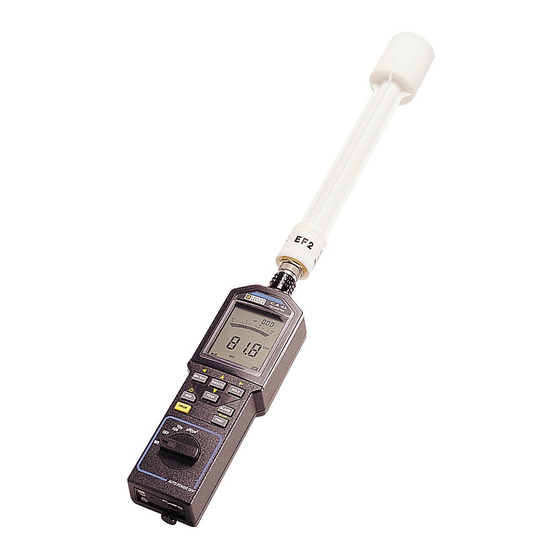
Ranger les éléments dans la mallette de transport. 9.2 SONDE EF2 La sonde EF2, livrée avec le C.A 43 étant isotropique, elle ne nécessite pas de manipulations spéciales. Son élément sensible mesure le champ selon 3 axes, sans avoir à déplacer la sonde dans les trois plans. -
Seite 25: Sortie Numérique
(voir schéma) : 10. SORTIE NUMÉRIQUE Le C.A 43 dispose d’une sortie numérique. Cette interface bi-directionnelle permet à l’appareil de communiquer avec des périphériques extérieurs. Pour relier l’appareil, utiliser la fibre optique et l’adaptateur opto-électrique. Celui-ci transforme le signal optique en signal électrique exploitable. -
Seite 26: Interrogation À Distance
Une trame se compose d’un ensemble d’informations qui ne peut pas être dissocié. Lorsqu’on imprime une mesure courante, cette trame équivaut à une ligne. Pour une mesure en mode enregistrement MIN/ MAX, elle est de trois lignes. Les niveaux de transmission sont établis comme suit : - Niveau 1 = Présence de lumière - Niveau 0 = Absence de lumière La vitesse de transmission est de 1200 bauds... -
Seite 27: Interrogation De La Mesure
Si l’appareil est en émission, il faut d’abord lui envoyer une transition 0 -> 1 sur l’entrée Rx. Cette information lui commande d’interrompre sa transmission. Puis, lorsque celle-ci est terminée, après l’envoi du code de fin de trame, lui envoyer la commande d’interrogation. Si cette dernière est envoyée trop tôt, elle ne sera pas entièrement décodée et l’appareil enverra le code ER 4. -
Seite 28: Interrogation De La Mémoire Mesure
Le deuxième groupe contient l’état de la fonction sur 3 caractères : - LO AL et HI AL si l’alarme n’est pas activée si l’alarme est activée - - - si l’alarme n’est pas en service - BAT Chiffre correspondant à l’autonomie restante de la pile en %. C’est le même chiffre qui est annoncé... -
Seite 29: Interrogation De La Mémoire Programme
11.4 INTERROGATION DE LA MÉMOIRE PROGRAMME Cette fonction est accessible dans tous les modes de fonctionnement. Codes à envoyer à l’appareil pour connaître le contenu de la mémoire programme : - 2A Hexa, 42 décimal Graphisme correspondant : * La réponse à cette interrogation sera l’émission par l’appareil sur la sortie TxD, des codes correspondants aux valeurs contenues dans la mémoire. -
Seite 30: Exemple D'interrogation Rapide
ROUTINE02 print:print «Saisie de 100 mesures...(cf pictogramme ‘COM’ de l’appareil)» beep for N=1 to 100 delay 0.08 ‘ ajoute 20 mS pour de temps de traitement du C.A 43 gosub ROUTINE03 X1(N)=K next N beep print : print «Affichage des 100 mesures saisies:» : print for N=1 to 100 print «Valeur mesurée:»;X1(N) -
Seite 31: Démodulation Sonore
12. DÉMODULATION SONORE La fonction démodulation permet l’écoute, sur un haut parleur interne, de la modulation d’amplitude éventuellement présente sur le signal HF. Cette détection de modulation est limitée aux fréquences audibles, comprises entre 500 Hz et 5kHz. Le meilleur rendement est obtenu pour des champs mesurés compris entre 5 V/m et 30 V/m, avec une profondeur de modulation de 50% minimum. - Seite 32 „ Conditions de référence Grandeurs d’influence Conditions de référence Tolérances Température ambiante 20°C ± 2 K Humidité relative 60 % HR ± 10 % Tension pile ± 1 V Fréquence de mesure 150 MHz ± 1 % Niveau de champ 10,0 V/m ±...
-
Seite 33: Caractéristiques Mécaniques
- Résistance aux secousses : 100 secousses de 10 g dans les 3 axes (CEI 68-2-29). „ Dimensions et masse - C.A 43 (sans sonde) : 216 x 72 x 37 mm - 350 g - Sonde de mesure (EF1 / EF2) : longueur : 320 mm - diamètre : 50 mm... -
Seite 34: Entretien
14. ENTRETIEN 14.1 CHANGEMENT DE PILE Avant d’effectuer une mesure, s’assurer, en mettant en marche l’appareil, que le symbole de pile n’apparaît pas sur l’afficheur. Dans l’affirmative, il faut impérativement changer la pile. L’opérateur dispose d’une minute pour effectuer les opérations de changement de pile pour ne pas devoir refaire la mise à... -
Seite 35: Annexe
16. ANNEXE 16.1 CODAGE DE LA RÉPONSE À UNE INTERROGATION RAPIDE DE LA MESURE Les deux octets transmis en réponse à une interrogation rapide sont codés suivant une loi particulière : Un octet comprend deux chiffres codés en Hexadécimal appelés A pour le premier octet, et B pour le deuxième octet transmis. - Seite 36 Le tableau ci-dessous indique le numéro de la table de linéarisation affectée à chacun des 17 codes sonde. Code capteur Numéro table linéarisation Unité de mesure de 255 à 251 inhibition mesure Affichage ANT de 250 à 237 de 236 à 223 "...
- Seite 37 Coefficient de la table 03 sonde EF1 deuxième sensibilité : N° de droite Début Coef. a Coef. b 0 pt 33 pts 4,666 10e-2 33 pts 184 pts 1,298 10e-2 1,111 184 pts 748 pts 5,851 10e-3 2,423 748 pts 2704 pts 3,476 10e-3 4,199...
-
Seite 38: Safety Precautions
„ When the probe is fitted to the meter, avoid shaking the assembly, particularly in measurement mode. „ In order to keep the instrument in its accuracy class and to obtain optimum use, we advise against leaving the C.A 43 permanently exposed to fields higher than 300 V/m or 100 A/m. - Seite 39 CONTENTS 1. DESCRIPTION ..........41 12. SOUND DEMODULATION .....67 1.1. Case ..........41 13. SPECIFICATIONS ........67 1.2. Display ...........42 13.1 Electrical specifications ....67 2. PRESENTATION ........43 13.2 Mechanical specifications .....69 14. MAINTENANCE ........70 2.1 General ..........43 2.2 User manual labels .......43 14.1 Changing the battery ....70 3.
-
Seite 41: Description
1. DESCRIPTION 1.1. CASE Sound demodulation control Optical connector, digital link 4 position rotary switch PRGM button - Programming - Initialisation of the program memory MEM button - Memorisation of the measurement - Display of the memory address - Display of the remaining memory capacity - Initialisation of the measurement memory ... -
Seite 42: Display
1.2. DISPLAY Programming mode in operation Printout request mode. Clock Cancel automatic memorisation Rate of automatic memorisation Digital output or input in progress Digital display of battery capacity, clock, ∆t or scan duration Log scale Analogue display by 35 segment bargraph Arrow indicating end of scale Measurement unit in microWatts per cm²... -
Seite 43: Presentation
ON, and consequently its class of electromagnetic compatibility in accordance with the applicable standard. The C.A 43 is a small portable instrument that mesures the electric field present in the atmosphere surrounding its measurement probe. This probe consists of an aerial combined with a high frequency detector. The wide passband of this unit enables the measurement of electrical fields from 0.1 V/m to 200 V/m for frequencies between 100... -
Seite 44: Use
3. USE Your Fieldmeter consists of a case and a probe. to connect it, simply position it in the axis of the case, turn the probe and push it in. Lock in position by pulling the black ring on the probe towards the case (multi-contact push-pull socket). -
Seite 45: Special Functions
4. SPECIAL FUNCTIONS SWITCHING ON PERMANENTLY After 10 minutes of operation without pressing a button or turning the rotary switch or reading the digital output, a battery economy system puts the instrument to sleep. This auto Off is preceded by a beep and flashing of the digital display for one minute. -
Seite 46: Displaying The Present Time
These beeps can be suppressed it they seem too noisy to you. To do this, simultaneously press MIN MAX as you switch On with the rotary switch. The disappearance of the symbol from the screen shows that the beep is switched Off. This deactivation of the beep will be continued even after the instrument is switched off (switch to the OFF position). -
Seite 47: Erasing The Program Memory
Group 1 contains 4 characters lined up on the left, indicating the programmed function. They are given in the following order: LO AL : For the low threshold HI AL : For the high threshold SCAN : For the number of minutes of the Scan (display HH MM) ∆t For the duration of the time interval expressed in hours, minutes and separating two sets of data in the memory. -
Seite 48: Erasing The Measurement Memory
ERASING THE MEASUREMENT MEMORY To initialise the measurement memory, press simultaneously on MEM when switching On with the rotary switch and do not release until it is erased. The MEM symbol lights up, the Init message is continuously displayed (top right) for 3 seconds and the number of addresses available appears on the digital display. -
Seite 49: Hold The Digital Display
The PEAK function allows you to make measurements with an acquisition speed of 1ms for peak measurements. The 50 Hz filter for rejection of low frequency fields is suppressed. The C.A 43 becomes sensitive to the power supplies of electric equipment, mains cable runs, ... - Seite 50 MAX value Similarly, a measurement higher than the value contained in the MAX register will cause it to be updated. Each time the contents of the MAX register is modified, a beep is emitted. AVERAGE value Initially, the average value corresponds to the value displayed when MIN MAX is first pressed. Every second the instrument inputs the digital measurement, then it takes the sum of all the values input since the beginning of the record command and divides the whole by the number of seconds that have gone by.
-
Seite 51: Alarm On / Off
Press HOLD again to stop recording MIN, MAX and AVG values: - The HOLD and PAUSE symbols disappear. - The digital display indicates the current measurement or the contents of the MIN, MAX or AVG registers on read mode. - The instrument is again on MIN, MAX and AVG mode but the registers have not yet been reinitialised and they contain the MIN, MAX and AVG values present before HOLD was used. - Seite 52 Sound signal : The minimum duration of operation of the buzzer on an alarm is 400ms even when this takes place on a peak value of lesser duration. When a threshold is crossed, a hysteresis of 1% is applied to its set point, which obliges the measurement to fall below this lesser value to exit the alarm.
-
Seite 53: Memory Mode
The maximum address, 1920, is displayed. AUTOMATIC MEMORISATION The C.A 43 Fieldmeter can be used for site monitoring. With a ∆t session programmed from 1 minute to 24 hourss, the min, max and average values corresponding to each session are memorised automatically. -
Seite 54: Read Measurement Memory
Automatic memorisation mode is stopped by pressing MIN MAX for more than two seconds. During memorisation, if the rotary switch or the measurement probe are handled, the function is also stopped. Notes : The MIN, MAX and AVG values accessible in measurement mode for reading with the MIN MAX button are not memorised. - Seite 55 ▼ If you continue to press the decrease button , the display is scrolled more quickly. The symbols and the digital values become illegible but the bargraph allows you to easily and quickly follow the evolution of the memorised values. The decrease is stopped at the first memorisation made.
-
Seite 56: Print Mode
7. PRINT MODE 7.1. MANUAL PRINTOUT On measurement function or memorisation function, each press on PRINT transmits to the TxD optical output a series of data in the following form: <Time> <Filter> <Function> <Measurement> <Unit> Each group is separated by 1 space. The output of the five groups is ended by a carriage return and 2 line paper advance. -
Seite 57: Automatic Printout
7.2 AUTOMATIC PRINTOUT When the Scanning function (printout every n minutes) is programmed, press PRINT to start the measurements printing cycle with the SCAN time interval programmed. This cycle starts by printing the measurement displayed when this command is sent. The SCAN symbol remains lit on the display throughout the duration of operation of the automatic printout mode. -
Seite 58: Writing A Number
Note : Before entering the values, check the position of the rotary switch and the type of probe used. The choice of unit depends on this position (A/m, V/m, µW/cm²). Manipulation of the switch, or changing the probe, exits the Fielfmeter from the program mode. 8.2 WRITING A NUMBER After having chosen the function to program, the former value (a number of three hyphens) is displayed. -
Seite 59: Re-Reading Programs
9.1 OPERATING PROCEDURE „ Connect the appropriate measurement probe to the C.A 43. The connection is made through the multicontact push-pull socket located at the top of the instrument. Position the probe in the axis of the case, „... -
Seite 60: Probe Ef2
PEAK to identify the peaks, some of which may exceed the maximum level that is wanted. (Example: the peaks due to the closeness of a neon light are often greater than 3V/m and cannot be classed as level II in accordance with IEC 801-3 and IEC 1000-4-3). The PEAK function switches OFF the 50Hz rejection fliter for low frequency fields. -
Seite 61: Digital Output
10. DIGITAL OUTPUT The C.A 43 has a digital output. this bi-directional interface allows the instrument to communicate with external peripherals. To connect the instrument, use the optic fibre and the opto-electric adaptor. This transforms the optic signal into a usable electric signal. The optic fibre connects to the COM output of the instrument (see lug for correct position). -
Seite 62: Remote Dead
A frame consists of a set of information which can not be separated. When you print a current measurement, this frame is equivalent to a line. For a measurement in MIN/MAX recording mode, it is three lines. The transmission levels are set as follows: - Level 1 = light present - Level 0 = no light present The transmission rate is 1200 bauds... -
Seite 63: Read Measurement
If the instrument is on emission, you must first send it a transition 0 -> 1 on the input Rx. This information commands it to interrupt its transmission. Then, when this is terminated, after sending the end of frame code, the message command is sent. If the latter is sent too early, it will not be entirely decoded and the instrument will send the error code ER4. -
Seite 64: Read The Measurement Memory
The second group contains the state of the function in 3 characters: - LO AL and HI AL OFF if the alarm is not On if the alarm is On - - - if the alarm is not in service - BAT Digit corresponding to the remaining service life of the battery in %. -
Seite 65: Read The Memory Program
11.4 READ THE MEMORY PROGRAM This function is accessible in all operating modes. Codes to send to the instrument to obtain the contente of the memory program: - 2A Hexa, 42 decimal Corresponding graphic: * The response to this message will be the emission by the instrument, to the TxD output, of the codes corresponding to the values contained in the memory. -
Seite 66: Example Of Rapid Readout
Measurement decoding is done in accordance with probe table 231. The language used is Turbo Basic. p=0 : dim X1(200) ‘creation of the data table gosub ROUTINE01 gosub ROUTINE02 print:print «Retrieval of 100 points ... see COM display on C.A 43» beep for N=1 to 100 delay 0.08 ‘‘delays by 20 mS to allow for C.A 43 processing time... -
Seite 67: Sound Demodulation
12. SOUND DEMODULATION The demodulation function allows the amplitude modulation which may be present on the HF signal to be heard on an internal loud speaker. This detection of modulation is limited to the audible frequencies between 500 Hz and 5kHz inclusive. The best result is obtained for fields measured between 5 V/m and 30 V/m inclusive with a modulation depth of 50% minimum. - Seite 68 „ Reference conditions Distortion magnitudes Reference conditions Tolerances Ambient temperature 20°C ± 2 K Relative humidity 60 % HR ± 10 % Battery voltage ± 1 V Field frequency 150 MHz ± 1 % Field level 10.0 V/m ± 0.1 V/m „...
-
Seite 69: Mechanical Specifications
- Bump resistance: 100 bumps of 10 g in the 3 axes (IEC 68-2-29). „ Dimensions and weight - C.A 43 (without probe): 216 x 72 x 37 mm - 350 g - measurement probe (EF1/EF2): length : 320 mm - diameter : 50 mm... -
Seite 70: Maintenance
14. MAINTENANCE 14.1 CHANGING THE BATTERY Before making a measurement, check by switching On the instrument that the battery symbol is not visible on the display. If it is, you must change the battery. The user has one minute in which to change the battery without having to reset the clock. Open the battery compartment at the back of the instrument using a coin (tool release screw). -
Seite 71: Appendix
16. APPENDIX 16.1 CODING THE RESPONSE TO A RAPID READOUT OF THE MEASUREMENT The two bytes transmitted in response to a rapid instruction are coded according to a special law. A byte comprises two digits coded in Hexadecimal called A for the first byte, and, et B for the sencond byte transmitted. - Seite 72 Probe code Linearisation table number Measurement Unit from 255 to 251 Measurement blocked Display ANT from 250 to 237 from 236 to 223 " from 222 to 209 " from 208 to 195 " from 194 to 181 " from 180 to 167 "...
- Seite 73 Coefficient of table 03 probe EF1 second sensitivity: N° straight line Start Coeff. a Coeff. b 0 ct 33 cts 4.666 10e-2 33 cts 184 cts 1.298 10e-2 1.111 184 cts 748 cts 5.851 10e-3 2.423 748 cts 2704 cts 3.476 10e-3 4.199 27040 cts...
-
Seite 74: Sicherheitshinweise
Nähe des Gerätes zu bleiben, wenn sich dieses in einem solchen Feld befindet. „ Vor Durchführung einer Messung vergewissern Sie sich beim Einschalten des C.A 43, daß auf der Anzeige nicht das Batteriesymbol (35) erscheint. Andernfalls ist die Batterie auszuwechseln. - Seite 75 INHALT 1. BESCHREIBUNG ........77 9. EINSATZ DER MESSONDEN ....96 1.1. Gerät ..........77 9.1 Inbetriebnahme .......96 1.2. Anzeige ..........78 9.2 Sonde EF2 ........97 2. GERÄTEINFORMATIONEN .....79 9.3 Sonde EF1 ........97 2.1 Allgemeines ........79 10. DIGITALAUSGANG ........98 2.2 Etiketten mit vereinfavhter 11. FERNABFRAGE ........99 bedienungsanleitung ......79 11.1 Messwertabfrage ......100 3.
-
Seite 77: Beschreibung
1. BESCHREIBUNG 1.1. GERÄT Schalter für akustische Demodulation Anschluß für Lichtleitfaser, digitale Datenleitung Drehschalter mit 4 Positionen Taste PRGM - Programmieren - Initialisieren des Programmspeichers Taste MEM - Meßwertspeicherung - Anzeige der Speicheradresse - Anzeige der verbleibenden Speicherkapazität - Initialisieren des Meßwertspeichers ... -
Seite 78: Anzeige
1.2. ANZEIGE Programmiermodus eingeschaltet Druckbefehl erteilt Automatische Speichersitzung Zeittakt für automatischen Ausdruck Datenempfang oder -sendung am Digitalausgang läuft Digitalanzeige der Batteriekapazität, Uhrzeit, ∆t oder Dauer des Scanvorgangs Logarithmenskala Analoganzeige mit 35-Segment-Bargraph Pfeilspitze zeigt die Überschreitung der Skala an Meßeinheit in Mikrowatt pro Quadratzentimeter Meßeinheit in Volt/Meter Meßeinheit in Ampere/Meter 2000-Punkt-Digitalanzeige... -
Seite 79: Geräteinformationen
Gerät verursacht wird und somit welcher elektromagnetischen Verträglichkeitsklasse es laut geltender Norm angehört. Das C.A 43 ist ein handliches und tragbares Gerät, das die Stärke des elektrischen Feldes in der Umgebung seiner Meßsonde mißt. Diese Sonde besteht aus einer Antenne in Verbindung mit einem Hochfrequenzdetektor. Die groβe Bandbreite dieser Vorrichtung ermöglicht die Messung elektrischer Felder von 0,1 V/m bis zu 200 V/m... -
Seite 80: Betrieb Des Gerätes
3. BETRIEB DES GERÄTES Ihr Feldstärkenmesser besteht aus dem Meßgerät und einer Sonde. Zum Anschluß der Sonde halten Sie diese in gleicher Richtung über das Meßgerät. Drehen Sie die Sonde bis Nut und Ausbuchtung übereinstimmen und stecken Sie die Sonde auf das Gerät. Verriegeln Sie die Sonde durch Ziehen des schwarzen Rings an der Sonde in Richtung zum Gerät (Multikontaktstecker). -
Seite 81: Sonderfunktionen
4. SONDERFUNKTIONEN DAUERBETRIEB Nach zehnminütiger Einschaltzeit ohne Betätigung einer Taste oder des Drehschalters oder Abfrage des Digitalausgangs wird das Gerät durch eine Batteriesparschaltung auf Sparbetrieb geschaltet. Dieser automatischen Abschaltung geht ein akustisches Signal voraus. Außerdem blinkt die Digitalanzeige für die Dauer einer Minute. Wenn während des Blinkens der Anzeige eine Taste des Gerätes betätigt wird, schaltet es für weitere 10 Minuten mit den vorgewählten Funktionen und ohne Berücksichtigung der «Wecktaste»... -
Seite 82: Anzeige Der Laufenden Uhrzeit
Wenn Ihnen diese akustischen Signale zu laut sind, können Sie sie abschalten. Zu diesem Zweck betätigen Sie beim Einschalten des Gerätes mit dem Drehschalter gleichzeitig die Taste MIN MAX . Das Verschwinden des Symbols zeigt an, daß das akustische Signal abgeschaltet ist. Diese Abschaltung bleibt auch nach dem Abschalten des Gerätes (Drehschalter auf Position OFF) gespeichert. -
Seite 83: Löschen Des Programmspeichers
Jede Zeile enthält drei Gruppen von Informationen, die durch eine Leerstelle getrennt sind und endet mit einem Carriage Return und einem Zeilensprung. <Gruppe 1> <Gruppe 2> <Gruppe 3> Gruppe 1 enthält 4 links ausgerichtete Zeichen, die die programmierten Funktionen anzeigen. Sie werden in folgender Reihenfolge angezeigt: LO AL : Unterer Schwellwert... -
Seite 84: Löschen Des Messwertspeichers
LÖSCHEN DES MESSWERTSPEICHERS Um den Meßwertspeicher zu initialisieren, betätigen Sie beim Einschalten anhand des Drehschalters gleichzeitig die Taste und halten sie gedrückt bis zum Löschen des Speicherinhalts. Die Anzeige MEM erscheint, die Mitteilung erscheint (oben rechts) für die Dauer von drei Sekunden und auf der Digitalanzeige wird die Anzahl der verfügbaren Speicheradressen angezeigt. -
Seite 85: Festhalten Des Angezeigten Messwertes
FESTHALTEN DES ANGEZEIGTEN MESSWERTES Durch Betätigen der Taste PRGM kann der letzte Meßwert auf der Digitalanzeige festgehalten werden, während die Analoganzeige weiterhin den momentanen Meßwert anzeigt. Auf der Anzeige erscheint . Ein weiterer Druck auf die Taste schaltet das Gerät wieder auf die Anzeige der PRGM momentanen Meßwerte und verschwindet wieder von der Anzeige. - Seite 86 Mindestwert (MIN) Sobald die Taste MIN MAX gedrückt wurde, wird der angezeigte Meßwert im Register «MIN» gespeichert. Liegt ein Meßwert unter dem gespeicherten Wert, wird dieser neue Wert in den Speicher übernommen lang ertönt ein akustisches Signal. Höchstwert (MAX) Liegt ein Meßwert über dem Wert, der im Register «MAX» gespeichert ist, wird das Register aktualisiert.
-
Seite 87: Angezeigter Meßwert
- In jedem Falle zeigt die Analoganzeige (BARGRAPH) ständig den laufenden Meßwert mit einer Wiederholfolge von 20 ms an. Funktion HOLD während der Aufzeichnung von MIN, MAX und AVG Wird HOLD gedrückt, während RECORD angezeigt wird: und PAUSE auf. - leuchten - wird die Aufzeichnung angehalten und die Meßwerte in den Registern MIN, MAX und AVG sind die letzten Werte, die vor Betätigen von HOLD aufgezeichnet wurden, - zeigt die Digitalanzeige den letzten Meßwert an, oder den Wert von MIN, MAX, AVG wenn sich das... -
Seite 88: An- / Abschalten Der Alarmfunktionen
AN- / ABSCHALTEN DER ALARMFUNKTIONEN Wenn Schwellwerte programmiert worden sind, aktiviert ein Druck auf ALARM die Feststellung von Überschreitungen dieser Schwellwerte. Die Symbole oder oder beide erscheinen auf der Anzeige, je nachdem, welcher Schwellwert programmiert worden ist. Auf dem Bargraph werden den Schwellwerten entsprechende Segmente, invertiert dargestellt. -
Seite 89: Speichern
Speicheradresse mit der Nummer 1920. AUTOMATISCHE MESSWERTSPEICHERUNG Das Feldstärkenmeßgerät C.A 43 kann für die örtliche Überwachung eingesetzt werden. Bei einem programmierten Meßtakt ∆t von 1 Minute bis zu 24 Stunden werden die Höchst-, Mindest- und Mittelwerte jeder Sitzung automatisch gespeichert. -
Seite 90: Abrufen Des Messwertspeichers
Bei jedem Speichervorgang blinkt das Symbol MEM einmal, und es ertönt ein akustisches Signal. Wenn der Meßwertspeicher voll ist (1920 Adressen), blinkt das Symbol MEM, und die Meßwertspeicherung wird beendet. Der automatische Speichermodus wird durch Betätigen der Taste MIN MAX mit einer Dauer von mehr als zwei Sekunden abgeschaltet. - Seite 91 Die erste aufgerufene Adresse enthält die Parameter des Meßwertes AVG (die Anzeige der Uhr ▼ enthält die programmierte Dauer für ∆t). Durch Betätigen von werden die Parameter des Meßwertes MAX aufgerufen (die Uhr nennt die Uhrzeit, an der dieser Höchstwert registriert wurde).
-
Seite 92: Ausdrucken
Während der Schnellsuche kann es vorkommen, daß mehrere Serien von gespeicherten Meßwerten angezeigt werden, die mit verschiedenen Maßeinheiten aufgezeichnet wurden. In diesem Falle hält die Anzeige bei jeder Veränderung der Maßeinheit an, und die Alarmfunktionen werden abgeschaltet. Wenn kein Schwellwert programmiert wurde, ist die Taste ALARM inaktiv.Für die eventuelle Festlegung eines Schwellwertes ist in den Programmiermodus umzuschalten. -
Seite 93: Automatischer Ausdruck
In der Funktion Speicherabruf, wird bei einem Druck auf PRINT der Speicherinhalt an den Digitalausgang übermittelt, beginnend mit der letzten Speicherung bis hinunter zur ersten Speicherung. Die Informationen werden in der gleichen Form (siehe vorangehender Absatz) ausgegeben. Das Symbol zeigt an, daß es sich um einen Ausdruck des Meßwertspeichers handelt. Die Uhrzeit entspricht derjenigen der einzelnen Aufzeichnungen. -
Seite 94: Programmieren
8. PROGRAMMIEREN 8.1 ALARM / MESSITZUNG ∆t / UHRZEIT / ZEITTAKT SCAN Ein Druck auf die Taste PRGM im Meßmodus startet den Modus «Programm». In der Anzeige erscheint das Symbol PRGM. Dieser Befehl unterdrückt alle Funktionen, die gerade aktiv sind, einschließlich des Digitalausgangs. Die verschiedenen Symbole dieser Funktionen erlöschen, und das Gerät nimmt keine weiteren Messungen mehr vor. -
Seite 95: Sonderfälle Bei Der Messung Μw/Cm²
Um die aktive Ziffer anzuheben, ist die Taste gedrückt zu halten. Analog dazu halten Sie zum ▼ Senken des Zahlenwertes die Taste gedrückt. Eine Veränderung nach oben (... 7, 8, 9, 0, 1, 2 ...) oder nach unten (... 3, 2, 1, 0, 9, 8, 7 ...) der aktiven Ziffer über die Null hinaus verändert automatisch auch die Ziffer(n) links dieser Ziffer. -
Seite 96: Einsatz Der Messonden
Signaltransparenz gewährleistet ist, die das elektrische Feld nicht stört, in dem sich Meßgerät und Antenne befinden. 9.1 INBETRIEBNAHME „ Geeignete Meßsonde auf das C.A 43 aufstecken. Der Anschluß erfolgt anhand des Steckverbinders auf der Oberseite des Geräts. Halten Sie die Meßsonde in gleicher Richtung wie das Gerät, „... -
Seite 97: Sonde Ef2
Sonde aus dem Gerät herausziehen. Beide Teile in der Transportkoffer aufräumen. 9.2 SONDE EF2 Da die Sonde EF2, die zusammen mit dem C.A 43 geliefert wird isotropisch ist, benötigt sie keine besondere Handhabung. Ihr Meßelement mißt das Feld in drei Richtungen, ohne daß die Antenne in diesen drei Ebenen bewegt werden muß. -
Seite 98: Digitalausgang
10. DIGITALAUSGANG Das Meßgerät C.A 43 besitzt einen Digitalausgang. Anhand dieser bidirektionalen Schnittstelle kann das Gerät mit Peripheriegeräten kommunizieren. Zum Anschluß des Gerätes sind der Lichtwellenleiter und der opto-elektronische Adapter zu verwenden. Dieser wandelt das optische Signal in ein verwertbares elektrische Signal um. Der Lichtwellenleiter wird an den COM-Ausgang des Gerätes angeschlossen (Verdrehungsschutz). -
Seite 99: Fernabfrage
Die Übertragung erfolgt anhand von zwei Lichtwellenleitern : - RxD Datenempfang - TxD Datenübertragung Dieses Interface ermöglicht die Übertragung der Meßergebnisse, des Inhalts der Programm- oder Meßwertspeicher und des Gerätezustands. Diese Übertragung erfolgt anhand eines Steuerbefehls. Dies kann ein lokaler Befehl, direkt am Gerät sein, oder ein Befehl, der von einer externen Steuereinheit erteilt wird. -
Seite 100: Messwertabfrage
11.1 MESSWERTABFRAGE Code, die an das Gerät zu senden sind, um den momentanen Meßwert zu erfahren : - 3F Hexadezimal, 63 Dezimal graphisches Zeichen : ? Damit diese Abfrage wirksam werden kann, muß sich das Gerät in der Betriebsart Messen oder Aufzeichnen befinden. -
Seite 101: Abfrage Des Messwertspeichers
Der Code für die Sonde ist eine Zahl zwischen 0 und 255. Diese Zahl definiert die Linearisierungskurven, die zu verwenden sind, um die Anzeige in der gewählten Maßeinheit zu erhalten. Ein Wert zwischen 251 und 255 zeigt an, daß keine Sonde angeschlossen ist. Ein Wert zwischen 250 und 139 zeigt an, daß... -
Seite 102: Schnelle Messwertabfrage
11.5 SCHNELLE MESSWERTABFRAGE Mit dieser Abfrage erhalten Sie Meßwerte mit einer sehr geringen Zeitkonstante. Auf diese Weise ist eine Verarbeitung durch einen angeschlossenen Rechner möglich. Um berücksichtigt zu werden, muß diese Abfrage an das Gerät gesendet werden, wenn es sich im Modus Messen oder Aufzeichnen befindet, andernfalls sendet das Gerät einen Fehlercode zurück : - Fehlercode 1 wenn sich das Gerät im Modus Speicherabfrage befindet... -
Seite 103: Akustische Demodulation
print :print «**** Programm - Ende ****» : close #1 ‘==================== U N T E R P R O G R A M M E ====================== ROUTINE01: ‘tabelle für Sonde 231 als Beispiel... B(1)=00000:F(1)=000033:CF(1)=4.666e-2:Q(1)=00.000 B(2)=00033:F(2)=000250:CF(2)=9.953e-3:Q(2)=01.211 B(3)=00250:F(3)=000820:CF(3)=5.438e-3:Q(3)=02.340 B(4)=00820:F(4)=002640:CF(4)=3.022e-3:Q(4)=04.322 B(5)=02640:F(5)=011776:CF(5)=1.893e-3:Q(5)=07.300 B(6)=11776:F(6)=143360:CF(6)=1.294e-3:Q(6)=14.360 return ROUTINE02: print «Initialisierung RS 232 auf COM1...»... -
Seite 104: Technische Daten
13. TECHNISCHE DATEN 13.1 ELEKTRISCHE CHARAKTERISTIKEN Meßspanne : FUNKTION MESSBEREICH V / m 0,1 bis 199,9 µW / cm² 0,1 bis 1999 A / m 0,1 bis 19,99 „ Bandbreite : von 100 kHz bis 2,5 GHz Die Messung im Bereich von 100 kHz bis 1 MHz besitzt einen Hinweischarakter. „... - Seite 105 „ Veränderungen im Anwendungsbereich Grenzen des maximale Einflußgröße beeinflußte Größe Anwendungsbereiches Veränderung 0,3 % / °C Umgebungstemperatur von 0 bis 50°C alle der Anzeige ± 0,5 V/m bei 10 °C von 10 bis 90 % Feuchtigkeit alle < 0,5 V/m ohne Kondensation Stromversorgung von 7,5 bis 11 V alle...
-
Seite 106: Mechanische Charakteristiken
- Erschütterungsfestigkeit : 100 Erschütterungen mit 10 g in den drei Ebenen (IEC 68-2-29). „ Abmessungen und Gewicht - C.A 43 (ohne Sonde) : 216 x 72 x 37 mm - 350 g - Meßsonde (EF1/EF2) : Länge : 320 mm Durchmesser : 50 mm 14. -
Seite 107: Reinigung
14.2 REINIGUNG Die Reinigung des Meßgerätes kann anhand jeglicher nichtschleifender und säurefreier Reinigungsmittel erfolgen. 14.3 WARTUNG Eingriffe für die Beseitigung eventueller Störungen sind vereinfacht, da das Feldstärkenmeßgerät nur über eine einzige Platine verfügt, auf der alle Komponenten zusammengefaßt sind. Allerdings kann die Reparatur nur durch qualifiziertes Personal erfolgen. -
Seite 108: Anhang
16. ANHANG 16.1 CODIERUNG DER ANTWORT AUF EINE SCHNELLE MESSWERTABFRAGE Die beiden Bytes, die als Antwort auf eine Schnellabfrage übertragen werden, sind in Übereinstimmung mit einer besonderen Regel codiert : Ein Byte besteht aus zwei Hexadezimalzahlen mit der Bezeichnung A1 und A2 beim ersten Byte und B1 und B2 beim zweiten Byte. - Seite 109 Nummer der Linearisierungs- Sondencode Maßeinheit tabelle von 255 bis 251 keine Messung Anzeige ANT von 250 bis 237 von 236 bis 223 " von 222 bis 209 " von 208 bis 195 " von 194 bis 181 " von 180 bis 167 "...
- Seite 110 Koeffizient der Tabelle 03 Sonde EF1 zweite Empfindlichkeit : N° der Geraden Anfang Ende Koeff. a Koeff. b 0 Pkte 33 Pkte 4,666 10e-2 33 Pkte 184 Pkte 1,298 10e-2 1,111 184 Pkte 748 Pkte 5,851 10e-3 2,423 748 Pkte 2704 Pkte 3,476 10e-3 4,199...
- Seite 112 FRANCE INTERNATIONAL Chauvin Arnoux Group Chauvin Arnoux Group 190, rue Championnet Tél : +33 1 44 85 44 38 75876 PARIS Cedex 18 Fax : +33 1 46 27 95 69 Tél : +33 1 44 85 44 85 Our international contacts Fax : +33 1 46 27 73 89 info@chauvin-arnoux.com...