
Verwandte Anleitungen für Star TSP800-Serie


Inhaltszusammenfassung für Star TSP800-Serie
- Seite 1 All manuals and user guides at all-guides.com THERMAL PRINTER TSP800 SERIES USER’S MANUAL MODE D’EMPLOI BEDIENUNGSANLEITUNG MANUALE DI ISTRUZIONI...
- Seite 2 • The contents of this manual are subject to change without notice. • All efforts have been made to ensure the accuracy of the contents of this manual at the time of going to press. However, should any errors be detected, STAR would greatly appreciate being informed of them.
-
Seite 3: Inhaltsverzeichnis
Appendix D: Serial Interface ................91 D-1. RS-232C Connector ................91 D-2. Cable Connections ................92 D-3. Electrical Characteristics ..............92 Appendix E: Periheral Unit Drive Circuit ............93 Appendix F: Memory Switch Settings .............94 Please access the following URL http://www.star-micronics.co.jp/service/sp_sup_e.htm for the lastest revision of the manual. -
Seite 4: Parts Identification And Nomenclature
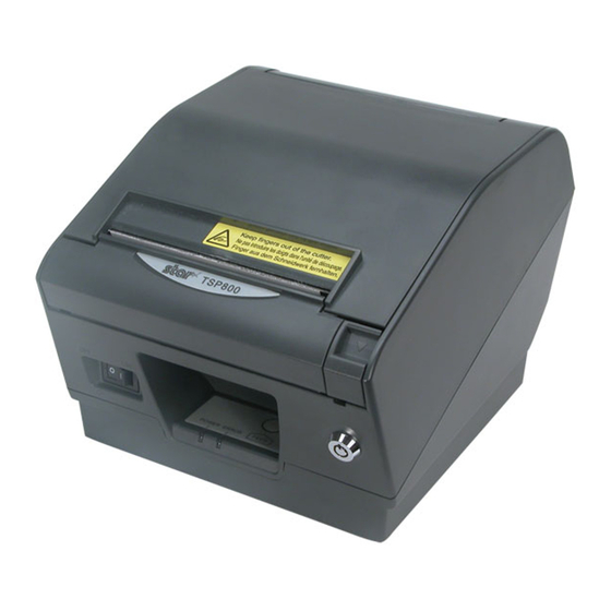
All manuals and user guides at all-guides.com 1. Parts Identification and Nomenclature Printer cover Open this cover to load or replace paper. Power switch Used to turn on/off power to the printer. Control panel Cover open lever Features LED indica- Pull this lever in the tors to indicate printer direction of the... -
Seite 5: Choosing A Place For The Printer
All manuals and user guides at all-guides.com Choosing a place for the printer Before actually unpacking the printer, you should take a few minutes to think about where you plan to use it. Remember the following points when doing this. Choose a firm, level surface where the printer will not be exposed to vibration. -
Seite 6: Consumable Parts And Ac Adapter
All manuals and user guides at all-guides.com 2. Consumable Parts and AC Adapter When consumable parts have run out, use those specified in the table below. Make sure that the AC adapter specified in the table is used. Use of consumable parts or AC adapter which are not specified in the table may result in damage to the printer, fire or electric shock. - Seite 7 (3) AC adapter (option) Model name: PS60-24 A Input: 100 to 240 V AC, 50/60 Hz Output: DC24±5%, 2.0 A (5.0 A Load 10 sec. Max) Important! Access the following URL for the information of the recommended paper. http://www.star-micronics.co.jp/ – 4 –...
-
Seite 8: Connecting Cables And Ac Adapter
All manuals and user guides at all-guides.com 3. Connecting Cables and AC Adapter 3-1. Interface Cable 3-1-1. Ferrite Core Installation (Parallel interface model only) (1) For only the parallel interface model, affix the ferrite core onto the cable as shown in the illustration below. Ferrite core Interface cable (2) Pass the fastener through the ferrite... -
Seite 9: Connecting The Interface Cable
All manuals and user guides at all-guides.com 3-1-2. Connecting the Interface Cable Note: Before connecting/disconnecting the interface cable, make sure that power to the printer and all the devices connected to the printer is turned off. Also make sure the power cable plug is disconnected from the AC outlet. -
Seite 10: Connecting To A Peripheral Unit
All manuals and user guides at all-guides.com 3-2. Connecting to a Peripheral Unit You can connect a peripheral unit to the printer using a modular plug. The following describes how to install the ferrite core and make the actual connection. See “Modular plug”... -
Seite 11: Connecting The Optional Ac Adapter
All manuals and user guides at all-guides.com 3-3. Connecting the Optional AC Adapter Note: Before connecting/disconnecting the AC adapter, make sure that power to the printer and all the devices connected to the printer is turned off. Also make sure the power cable plug is disconnected from the AC outlet. -
Seite 12: Turning Power On
All manuals and user guides at all-guides.com 3-4. Turning Power On Make sure that the AC adapter has been connected as described in 3-3. (1) Set the power switch located on the front of the printer to on. The POWER lamp on the control panel will light up. Power switch Important! We recommend that you unplug the printer from the power outlet... -
Seite 13: Control Panel And Other Functions
All manuals and user guides at all-guides.com 4. Control Panel and Other Functions 4-1. Control Panel 1 POWER lamp (Green LED) Lights when the power is ON 2 ERROR lamp (Red LED) Indicates various errors in combi- FEED POWER ERROR nation with POWER lamp 3 FEED button 3 FEED button... - Seite 14 All manuals and user guides at all-guides.com 3) Non recoverable error ERROR lamp Error Description POWER lamp Recovery Conditions RAM error This is not a recoverable error. Consult dealer for repairs. Flashes at 0.25 EPROM error Flashes at 0.25 This is not a recoverable error. second intervals second intervals Consult dealer for repairs.
-
Seite 15: Self Printing
All manuals and user guides at all-guides.com 4-3. Self Printing (1) Test Printing Turn the power on while holding the FEED button depressed. Test printing will be performed according to the Ver. No., DIP switch settings and character order. When the FEED button is depressed at the time of the end of test printing, only the characters will be printed out repeatedly. - Seite 16 All manuals and user guides at all-guides.com (2) Hexadecimal Dump Mode Open the printer cover, then turn the power on while holding the FEED button. When the cover is closed, “*** HEX DUMP PRINTING ***” is printed, and the printer enters the Hexadecimal Dump Mode. Each of the signals sent from the computer to the printer will be printed out in hexadecimal code.
-
Seite 17: Loading The Roll Paper
All manuals and user guides at all-guides.com 5. Loading the Roll Paper Be sure to use roll paper that matches the printer’s specification. Push the Cover open lever, and open the printer cover. Cover open lever While observing the direction of the roll, set the paper roll into the hollow, and pull on the leading edge of the paper toward you. - Seite 18 All manuals and user guides at all-guides.com Push down both sides of the printer cover to close. Note: Make sure that the printer cover is securely closed. Important! 1. Do not touch the cutter blade. · There is a cutter inside the paper outlet slot. Not only should you not put your hand in the paper outlet slot while printing is in progress, never put your hand into the outlet even when printing is not in progress.
-
Seite 19: Adjusting The Near-End Sensor
All manuals and user guides at all-guides.com 6. Adjusting the Near-end Sensor Use the following procedure to adjust the near-end sensor so it is compatible with the size of roll paper you are using. 1 Open the printer cover. 2 Determine the diameter of the roll paper you are using and find the required setting in the table below. - Seite 20 All manuals and user guides at all-guides.com Adjustment value according to the paper you are using Paper thick- When using the paper roll with a core whose inside diameter (A):ø12, outside diameter ness ( µ m) (B):ø18 Detected diameter (C) Remained paper length (Approx.
-
Seite 21: Preventing And Clearing Paper Jams
All manuals and user guides at all-guides.com 7. Preventing and Clearing Paper Jams 7-1. Preventing Paper Jams The paper should not be touched during ejection and before it is cut. Pressing or pulling the paper during ejection may cause a paper jam, paper cutting failure or line feed failure. -
Seite 22: Periodical Cleaning
All manuals and user guides at all-guides.com 8. Periodical Cleaning Printed characters may become partially unclear due to accumulated paper dust and dirt. To prevent such a problem, paper dust collected in the paper holder and paper transport section and on the surface of the thermal head must be removed periodically. - Seite 23 7-2. Correction de bourrages de papier ............38 8. Nettoyage ......................39 8-1. Nettoyage de la tête d’impression ............39 8-2. Nettoyage du support de papier ............39 APPENDICE ......................80 L’appendice n’est pas traduit. Pour obtenir la dernière version de ce manuel, consultez l’adresse URL suivante: http:/www.star-micronics.co.jp/service/sp_sup_e.htm. – 20 –...
-
Seite 24: Identification Des Pièces Et Nomenclature
All manuals and user guides at all-guides.com 1. Identification des pièces et nomenclature Capot de l’imprimante Ouvrez ce capot pour charger ou remplacer le papier. Interrupteur d’alimentation Permet la mise sous et hors tension de l’appareil. Levier d’ouverture du capot Panneau des commandes Tirez ce levier dans le sens de Le panneau est équipé... - Seite 25 All manuals and user guides at all-guides.com Emplacement de l’imprimante Avant de déballer l’imprimante, déterminez l’emplacement où vous souhaitez l’installer. Veuillez observer les points ci-dessous lors de votre choix. Choisissez une surface stable et de niveau sur laquelle l’imprimante ne sera exposée à aucune vibration. Assurez-vous que l’emplacement dispose d’une prise secteur proche et d’accès aisé.
-
Seite 26: Consommables Et Adaptateur Secteur
All manuals and user guides at all-guides.com 2. Consommables et adaptateur secteur Il convient d’utiliser exclusivement les types de papier figurant dans le tableau ci- dessous. Veillez également à utiliser l’adaptateur secteur qui figure dans le tableau. L’utilisation d’un type de papier et d’adaptateur ne figurant pas dans le tableau risque d’endommager l’imprimante, de causer un incendie ou une décharge électrique. - Seite 27 Nom du modèle: PS60-24 A Entrée: CA100 à 240 V, 50/60 Hz Sortie: CC24±5%, 2,0 A (charge de 10 sec à 5,0 A max.) Attention! Pour obtenir des informations concernant le papier recommandé, con- sultez l’adresse URL suivante : http://www.star-micronics.co.jp/. – 24 –...
-
Seite 28: Câbles De Connexion Et Adaptateur Secteur
All manuals and user guides at all-guides.com 3. Câbles de connexion et adaptateur secteur 3-1. Câble d’interface 3-1-1. Installation du tore de ferrite (modèle avec interface parallèle seulement) (1) Modèle avec interface parallèle seu- lement: fixez la grande gaine en ferrite sur le câble comme illustré. -
Seite 29: Connexion Du Câble D'interface
All manuals and user guides at all-guides.com 3-1-2. Connexion du câble d’interface Remarque:Avant de connecter ou déconnecter le câble d’interface, veillez à ce que l’imprimante et tous les appareils qui y sont connectés soient hors tension. Veillez également à débrancher le câble d’alimentation de la prise secteur. -
Seite 30: Raccordement D'un Appareil Périphérique
All manuals and user guides at all-guides.com 3-2. Raccordement d’un appareil périphérique Vous pouvez raccorder un appareil périphérique à l’imprimante à l’aide d’une fiche modulaire. Nous expliquons ci-dessous comment installer le tore de ferrite et faire le raccordement proprement dit. Pour les détails sur le type de fiche modulaire à... -
Seite 31: Connexion De L'adaptateur Secteur Optionnel
All manuals and user guides at all-guides.com 3-3. Connexion de l’adaptateur secteur optionnel Remarque:Avant de connecter ou déconnecter l’adaptateur secteur, veillez à ce que l’imprimante et tous les appareils qui y sont connectés soient hors tension. Veillez également à débrancher le câble d’alimentation de la prise secteur. -
Seite 32: Mise Sous Tension De L'imprimante
All manuals and user guides at all-guides.com 3-4. Mise sous tension de l’imprimante Assurez-vous d’avoir bien connecté l’adaptateur secteur comme décrit à la section 3-3. (1) Placez l’interrupteur d’alimentation, situé à l’avant de l’imprimante, sur la position sous tension. La DEL POWER s’allume au panneau des commandes. Interrupteur d’alimentation Attention! -
Seite 33: Panneau De Commande Et Autres Fonctions
All manuals and user guides at all-guides.com 4. Panneau de commande et autres fonctions 4-1. Panneau de commande 1 Témoin POWER (DEL verte) S’allume quand l’appareil est sous tension. 2 Témoin ERROR (DEL rouge) FEED POWER ERROR Indique des erreurs variées en com- binaison avec le témoin POWER. - Seite 34 All manuals and user guides at all-guides.com 3) Erreur non récupérable Témoin ERROR Description de l’erreur Témoin POWER Conditions de récupération Sous tension Erreur de mémoire Hors tension Ce n’est pas une erreur récupérable. vive Consultez votre revendeur pour des réparations.
-
Seite 35: Auto-Impression
All manuals and user guides at all-guides.com 4-3. Auto-impression (1) Essai d’impression Mettez l’appareil sous tension tout en maintenant la touche FEED enfoncée. L’essai d’impression sera effectué en fonction du numéro de version, des réglages du commutateur DIP et de l’ordre des caractères. Si vous appuyez sur la touche FEED à... - Seite 36 All manuals and user guides at all-guides.com (2) Mode de vidage hexadécimal Ouvrez le capot de l’imprimante, puis mettez l’appareil sous tension tout en maintenant la touche FEED enfoncée. Quand le capot est fermé, “*** HEX DUMP PRINTING ***” est imprimé et l’imprimante entre en mode de vidage hexadécimal.
-
Seite 37: Chargement Du Rouleau De Papier
All manuals and user guides at all-guides.com 5. Chargement du rouleau de papier Veillez à utiliser un rouleau de papier qui correspond aux spécifications de l’imprimante. Poussez le levier d’ouverture du capot et ouvrez le capot de l’imprimante. Levier d’ouverture du capot Mettez le rouleau de papier en place dans le creux tout en respectant son orientation, et tirez sur l’extrémité... - Seite 38 All manuals and user guides at all-guides.com Poussez vers la bas les deux côtés du capot de l’imprimante pour le fermer. Remarque: Assurez-vous que le capot de l’imprimante est bien fermé. Attention! 1. Ne pas toucher la lame du coupe-ruban. ·...
-
Seite 39: Réglage Du Capteur De Fin De Rouleau
All manuals and user guides at all-guides.com 6. Réglage du capteur de fin de rouleau Utilisez la procédure suivante pour régler le capteur de fin de rouleau conformé- ment à la taille du rouleau de papier utilisé. 1 Ouvrez le capot de l’imprimante. 2 Déterminez le diamètre du rouleau de papier utilisé... - Seite 40 All manuals and user guides at all-guides.com Valeur de réglage correspondant au papier utilisé. Épaisseur du Quand vous utilisez un rouleau de papier dont le diamètre intérieur du support est de papier (µm) (A):ø12 et le diamètre extérieur de (B):ø18 Diamètre détecté...
-
Seite 41: Prévention Et Correction De Bourrages De Papier
All manuals and user guides at all-guides.com 7. Prévention et correction de bourrages de papier 7-1. Prévention des bourrages de papier Il convient de ne jamais toucher le papier pendant son éjection et avant qu’il soit coupé. Appuyer ou tirer sur le papier pendant son éjection risque de provoquer un bourrage, des problèmes de coupure ou d’avance de ligne. -
Seite 42: Nettoyage
All manuals and user guides at all-guides.com 8. Nettoyage Les caractères imprimés pourraient devenir partiellement illisibles en raison de l’accumulation de la poussière de papier et de crasse. Afin de prévenir ce genre de problème, il convient de nettoyer régulièrement la poussière qui s’accumule sur le support de papier, les passages du papier et la surface de la tête d’impres- sion. - Seite 43 8-1. Reinigen des Thermalkopfes ..............59 8-2. Reinigen des Papierhalters ..............59 ANHANG ......................80 Der Anhand dieser Bedienungsanleitung ist nur in englischer Sprache. Bitte wenden Sie sich an die folgende Internet-Address: http://www.star-micronics.co.jp/service/sp_sup_e.htm, wenn Sie die neueste Revision dieses Handbuches lesen möchten. – 40 –...
-
Seite 44: Beschreibung Und Bezeichnung Der Geräteteile
All manuals and user guides at all-guides.com 1. Beschreibung und Bezeichnung der Geräteteile Abdeckung Diese Abdeckung öffnen, um Papier einzusetzen oder zu entnehmen. Nur Parallel-Schnitt- schnelle-Modell Zum Ein- oder Ausschal- ten des Druckers. Bedienfeld Abdeckung-öffnen-Hebel Mit LED-Anzeigen Diesen Hebel in Pfeilrichtung zur Anzeige des ziehen, um die Druckerabdeckung Druckerstatus und... - Seite 45 All manuals and user guides at all-guides.com Wahl eines Aufstellungsorts für den Drucker Bevor Sie den Drucker auspacken, sollten Sie einige Minuten damit verbringen, einen geeigneten Aufstellungsort auszusuchen. Denken Sie dabei an die folgenden Punkte: Den Drucker auf einem flachen, aber festen Untergrund aufstellen, wo keine Vibrationen vorhanden sind.
-
Seite 46: Verbrauchsteile Und Netzteil
All manuals and user guides at all-guides.com 2. Verbrauchsteile und Netzteil Wenn die Verbrauchsteile verbraucht sind, besorgen Sie Ersatz entsprechend der unten gezeigten Tabelle. Verwendung von Verbrauchsteilen oder Netzteilen, die nicht den unten aufge- führten Beschreibungen entsprechend, kann zu Schäden am Drucker, Bränden oder elektrischen Schlägen führen. - Seite 47 100 bis 240 V WS, 50/60 Hz Ausgang: 24 V GS±5%, max. 2,0 A (max. 10 s bei 5,0 A Last) Wichtig! Empfehlungen zu den zu verwendenden Papiersorten sind im Internet bei der folgenden URL erhältlich: http://www.star-micronics.co.jp/ – 44 –...
-
Seite 48: Anschlußkabel Und Netzteil
All manuals and user guides at all-guides.com 3. Anschlußkabel und Netzteil 3-1. Schnittstellenkabel 3-1-1. Anbringen des Ferritkerns (Nur beim Parallel- Schnittschnelle-Modell) (1) Nur beim Parallel-Schnittschnelle- Modell, Befestigen Sie den großen Ferritkern am Kabel, wie das in der folgenden Abbildung gezeigt wird. Ferritkern Kable Maximum... -
Seite 49: Anschließen Des Schnittstellenkabels
All manuals and user guides at all-guides.com 3-1-2. Anschließen des Schnittstellenkabels Hinweis:Vor dem Anschließen/Abtrennen des Schnittstellenkabels stellen Sie sicher, daß der Drucker und alle angeschlossenen Gerät ausge- schaltet sind. Außerdem sollte der Netzstecker abgezogen sein. (1) Schließen Sie das Schnittstellenkabel an die Buchse an der Rückseite des Druckers an. -
Seite 50: Anschluß An Ein Peripheriegerät
All manuals and user guides at all-guides.com 3-2. Anschluß an ein Peripheriegerät Es kann ein Peripheriegerät an den Drucker mit einem Modularstecker ange- schlossen werden. Im folgenden wird beschrieben, wie der Ferritkern angebracht und die Verbindung hergestellt wird. Siehe “Modularstecker” auf Seite 80 für den Typ von Modularstecker, der dazu erforderlich ist. -
Seite 51: Anschließen Des Optionalen Netzteils
All manuals and user guides at all-guides.com 3-3. Anschließen des optionalen Netzteils Hinweis:Vor dem Anschließen/Abtrennen des Netzteils stellen Sie sicher, daß der Drucker und alle angeschlossenen Gerät ausgeschaltet sind. Außerdem sollte der Netzstecker abgezogen sein. (1) Schließen Sie das Netzteil an das Netzkabel an. Hinweis:Verwenden Sie nur das vorgesehene Netzteil und Netzkabel. -
Seite 52: Einschalten
All manuals and user guides at all-guides.com 3-4. Einschalten Stellen Sie sicher, daß das Netzteil angeschlossen ist, wie in 3-3 beschrieben. (1) Den Netzschalter vorne am Gerät auf Ein (ON) stellen. Das POWER- Lämpchen am Bedienfeld leuchtet auf. Netzschalter Wichtig! Wir empfehlen, den Netzstecker aus der Steckdose zu ziehen, wenn der Drucker längere Zeit lang nicht benutzt werden soll. -
Seite 53: Bedienfeld Und Andere Funktionen
All manuals and user guides at all-guides.com 4. Bedienfeld und andere Funktionen 4-1. Bedienfeld 1 POWER-Lämpchen (grüne LED) Leuchtet in eingeschaltetem Zustand 2 ERROR-Lämpchen (rote LED) Zeigt in Kombination mit dem PO- FEED POWER ERROR WER-Lämpchen verschiedene Fehlerzustände an 3 FEED-Taste 3 FEED-Taste 2 ERROR-Lämpchen Die FEED-Taste drücken, um das... -
Seite 54: Papiererkennung-Fehler
All manuals and user guides at all-guides.com 3) Nicht behebbare Fehler ERROR-Lämpchen Fehlerbeschreibung POWER-Lämpchen Behebungsbedingungen Papierschnitt-Feh- Dies ist ein nicht behebbarer Fehler. Der Kundendienst muß bezüglich Reparatur kontaktiert werden. Blinkt im Abstand EEPROM-Fehler Blinkt im Abstand Dies ist ein nicht behebbarer Fehler. von 0,25 s von 0,25 s Der Kundendienst muß... -
Seite 55: Selbstdruck
All manuals and user guides at all-guides.com 4-3. Selbstdruck (1) Testdruck Das Gerät einschalten, während die FEED-Taste gedrückt gehalten wird. Der Testdruck wird entsprechend der Ver. Nr., den DIP-Schalter-Einstellun- gen und der Zeichenfolge ausgeführt. Wenn die FEED-Taste beim Ende des Testdrucks gedrückt wird, werden nur die Zeichen wiederholt ausgedruckt. - Seite 56 All manuals and user guides at all-guides.com (2) Sedezimaler Datenausdruck Die Druckerabdeckung öffnen, und dann einschalten, während die FEED- Taste gedrückt gehalten wird. Wenn die Abdeckung geschlossen wird, wird “***HEX DUMP PRINTING***” ausgedruckt, und der Drucker schaltet auf die Betriebsart sedezimaler Datenausdruck um. Jedes der vom Computer zum Drucker gesandten Signale wird nun als sedezimaler Code ausgedruckt.
-
Seite 57: Einlegen Der Papierrolle
All manuals and user guides at all-guides.com 5. Einlegen der Papierrolle Immer Rollenpapier verwenden, das zu den technischen Daten des Druckers paßt. Den Abdeckung-Öffnen-Hebel drük- ken, und die Druckerabdeckung öff- nen. Unter Beachtung der richtigen Einsetz- richtung der Rolle die Papierrolle in die Abdeckung-Öffnen-Hebel Vertiefung legen und die Vorderkante des Papiers nach vorne ziehen. - Seite 58 All manuals and user guides at all-guides.com Beide Seiten der Druckerabdeckung zum Schließen nach unten drücken. Hinweis: Sicherstellen, daß die Druckerabdeckung fest geschlossen ist. Wichtig! 1. Nicht die Schneidwerkklinge berühren. · Im Papierauslaßschlitz befindet sich ein Schneidwerk. Niemals die Hände in den Auslaßschlitz stecken, nicht nur während des Druck- betriebs sondern auch wenn der Drucker nicht arbeitet.
-
Seite 59: Einstellung Des Endanäherungs-Sensors
All manuals and user guides at all-guides.com 6. Einstellung des Endanäherungs-Sensors Den Endanäherungs-Sensor auf folgende Weise justieren, damit er der Größe der verwendeten Papierrolle entspricht. 1 Die Druckerabdeckung öffnen. 2 Den Durchmesser der verwendeten Papierrolle ermitteln, und in der untenste- henden Tabelle die entsprechende Einstellung aufsuchen. - Seite 60 All manuals and user guides at all-guides.com Einstellwerte entsprechend des verwendeten Papiers Papierdicke Bei Verwendung einer Papierrolle mit einem Kern mit Innendurchmesser (A):ø12 und (µm) Außendurchmesser (B):ø18 Erkannter Durchmesser (C) Rest papier (Etwa mm) (Etwa m) Niveau 1 Niveau 2 Niveau 3 Niveau 1 Niveau 2...
-
Seite 61: Verhindern Und Beheben Von Papierstau
All manuals and user guides at all-guides.com 7. Verhindern und Beheben von Papierstau 7-1. Verhindern von Papierstau Das Papier soll beim Ausgeben und vor dem Schneiden nicht berührt werden. Wenn das Papier beim Ausgeben gedrückt oder gezogen wird, kann ein Papiers- tau, ein Abschneidfehler oder ein Zeilenvorschubfehler verursacht werden. -
Seite 62: Regelmäßige Reinigung
All manuals and user guides at all-guides.com 8. Regelmäßige Reinigung Die Druckzeichen können durch Ansammlung von Papierstaub und anderem Schmutz unscharf werden. Um das zu verhindern, muß im Papierhalter und in der Papiertransportstufe angesammelter Staub von Zeit zu Zeit entfernt werden. Diese Reinigung sollte einmal alle sechs Monate oder einmal nach jeder Million Zeilen ausgeführt werden. - Seite 63 8-1. Pulizia della testina termica ..............79 8-2. Pulizia del comparto carta ..............79 APPENDICE ......................80 L’Appendice appare solo nella sezione in inglese di questo manuale. Visitare il seguente indirizzo URL http://www.star-micronics.co.jp/service/sp_sup_e.htm per accedere alla versione più recente del manuale. – 60 –...
-
Seite 64: Identificazione Delle Parti E Nomenclatura
All manuals and user guides at all-guides.com 1. Identificazione delle parti e nomenclatura Coperchio stampante Aprire questo coperchio per inserire o sostituire la carta. Interruttore di alimentazione Usarlo per accen- dere/spegnere la stampante. Leva di apertura coperchio Pannello di controllo Tirare questa leva in direzione della Dispone di indicatori LED freccia per aprire il coperchio della... - Seite 65 All manuals and user guides at all-guides.com Scelta di un luogo per la stampante Prima di disimballare la stampante, decidere dove si desidera installarla. Tenere presenti i seguenti punti. Scegliere una superficie stabile e in piano, dove la stampante non sia esposta a vibrazioni.
-
Seite 66: Parti Soggette A Consumo E Trasformatore Ca
All manuals and user guides at all-guides.com 2. Parti soggette a consumo e trasformatore CA Quando le parti soggette a consumo si sono esaurite, usare quelle specificate nella seguente tabella. Assicurarsi di usare il trasformatore CA specificato nella tabella. L’uso di parti soggette a consumo o di un trasformatore CA diversi da quanto specificato nella tabella può... - Seite 67 (3) Trasformatore CA (opzionale) Nome modello: PS60-24 A Ingresso: Da 100 a 240 V CA, 50/60 Hz Uscita: 24±5%CC, 2,0 A (5,0 A carico 10 sec. mass.) Importante! Accedere alla seguente URL per informazioni sulla carta consigliata. http://www.star-micronics.co.jp/ – 64 –...
-
Seite 68: Cavi Di Collegamento E Trasformatore Ca
All manuals and user guides at all-guides.com 3. Cavi di collegamento e trasformatore CA 3-1. Cavo interfaccia 3-1-1. Installazione dell’anello di ferrite (solo modello a interfaccia parallelo) (1) Solo per il modello a interfaccia parallelo, fissare l’anello di ferrite al cavo come mostrato nell’illustra- zione qui sotto. -
Seite 69: Collegamento Del Cavo Interfaccia
All manuals and user guides at all-guides.com 3-1-2. Collegamento del cavo interfaccia Nota: Prima di collegare/scollegare il cavo interfaccia, assicurarsi che la stampante e tutti i dispositivi collegati alla stampante siano spenti. Inoltre assicurarsi che la spina del cavo di alimentazione sia scollegata dalla presa di corrente. -
Seite 70: Collegamento Ad Un'unità Periferica
All manuals and user guides at all-guides.com 3-2. Collegamento ad un’unità periferica Si può collegare un’unità periferica alla stampante usando una spina modulare. Di seguito descriviamo come installare l’anello di ferrite ed eseguire il collega- mento. Vedere “Modulare necessario” a pagina 80 per dettagli sul tipo di spina modulare necessario. -
Seite 71: Collegamento Del Trasformatore Ca Opzionale
All manuals and user guides at all-guides.com 3-3. Collegamento del trasformatore CA opzionale Nota: Prima di collegare/scollegare il trasformatore CA, assicurarsi che la stampante e tutti i dispositivi collegati alla stampante siano spenti. Inoltre assicurarsi che la spina del cavo di alimentazione sia scollegata dalla presa di corrente. -
Seite 72: Accensione
All manuals and user guides at all-guides.com 3-4. Accensione Assicurarsi che il trasformatore CA sia stato collegato come indicato nella sezione 3-3. (1) Regolare su ON l’interruttore di alimentazione situato sul davanti della stampante. La spia POWER sul pannello di controllo si illumina. Interruttore di alimentazione Importante! Consigliamo di scollegare la stampante dalla presa di corrente quando... -
Seite 73: Pannello Di Controllo E Altre Funzioni
All manuals and user guides at all-guides.com 4. Pannello di controllo e altre funzioni 4-1. Pannello di controllo 1 Spia POWER (LED verde) Si illumina quando l’unità è accesa. 2 Spia ERROR (LED rosso) Indica vari errori in combinazione FEED POWER ERROR con la spia POWER. - Seite 74 All manuals and user guides at all-guides.com 3) Errori senza recupero Spia ERROR Descrizione dell’errore Spia POWER Condizioni di recupero Accesa Errore RAM Spenta Questo errore è senza recupero. Con- sultare il rivenditore per riparazioni. Lampeggia a in- Errore EPROM Lampeggia a in- Questo errore è...
-
Seite 75: Stampa Automatica
All manuals and user guides at all-guides.com 4-3. Stampa automatica (1) Stampa di prova Accendere l’unità tenendo premuto il tasto FEED. La stampa di prova viene eseguita nell’ordine di numero di versione, impostazioni degli interruttori DIP e ordine dei caratteri. Se si preme il tasto FEED alla fine della stampa di prova, sono stampati ripetutamente solo i caratteri. - Seite 76 All manuals and user guides at all-guides.com (2) Modo di scaricamento esadecimale Aprire il coperchio stampante, quindi accendere l’unità tenendo premuto il tasto FEED. Quando si chiude il coperchio viene stampato “*** HEX DUMP PRINTING***” e la stampante passa al modo di scaricamento esadecimale. Ciascuno dei segnali inviati dal computer alla stampante viene stampante come codice esadecimale.
-
Seite 77: Inserimento Del Rotolo Di Carta
All manuals and user guides at all-guides.com 5. Inserimento del rotolo di carta Assicurarsi di usare carta su rotolo che corrisponde alle specifiche della stampan- Spingere la leva di apertura coperchio e aprire il coperchio stampante. Leva di apertura coperchio Osservando l’orientamento del rotolo, inserire il rotolo di carta nel vano e tirare il bordo iniziale della carta verso... - Seite 78 All manuals and user guides at all-guides.com Premere su entrambi i lati del coper- chio stampante per chiudere. Nota: Assicurarsi che il coperchio stam- pante sia saldamente chiuso. Importante! 1. Non toccare la lama della taglierina. · All’interno della fessura di uscita carta si trova una taglierina. Non mettere mai la mano nella fessura di uscita della carta durante la stampa e non mettere mai la mano nella fessura anche quando la stampa non è...
-
Seite 79: Regolazione Del Sensore Di Esaurimento Prossimo
All manuals and user guides at all-guides.com 6. Regolazione del sensore di esaurimento prossimo Usare il seguente procedimento per regolare il sensore di esaurimento prossimo in modo che sia compatibile con le dimensioni del rotolo di carta usato. 1 Aprire il coperchio stampante. 2 Misurare il diametro del rotolo di carta usato e trovare l’impostazione necessaria nella tabella sotto. - Seite 80 All manuals and user guides at all-guides.com Valore di regolazione secondo la carta usata Spessore carta Quando si usa un rotolo di carta con nucleo di diametro interno (A):ø12, diametro (µm) esterno (B):ø18 Diametro individuato (C) Lunghezza carta rimanente (mm circa) (m circa) Livello 1 Livello 2...
-
Seite 81: Prevenzione E Soluzione Degli Inceppamenti Della Carta
All manuals and user guides at all-guides.com 7. Prevenzione e soluzione degli inceppamenti della carta 7-1. Prevenzione degli inceppamenti della carta La carta non deve essere toccata durante l’espulsione e prima che sia tagliata. Se si preme o si tira la carta durante l’espulsione si può verificare un inceppamento della carta, un mancato taglio della carta o un avanzamento di riga mancato. -
Seite 82: Pulizia Periodica
All manuals and user guides at all-guides.com 8. Pulizia periodica I caratteri stampati possono diventare parzialmente poco chiari a causa dell’ac- cumulo di polvere di carta e sporcizia. Per evitare tale problema, è necessario rimuovere periodicamente la polvere di carta accumulata nel comparto carta, nella sezione di trasporto carta e sulla superficie della testina termica. -
Seite 83: Appendix A: Specifications
All manuals and user guides at all-guides.com Appendix A: Specifications A-1. General Specifications (1) Printing method Direct line thermal printing (2) Print speed Max. 1200 dots/sec. (150 mm/sec.) (3) Dot density 203 dpi: 8 dots/mm (0.125 mm/dot) (4) Printing width Max. -
Seite 84: A-2. Auto Cutter Specifications
0.065 ~ 0.15 mm A-3. Interface (1) Interface RS232C serial interface or Two-way parallel inter- face (IEEE1284) (2) Command Star commands A-4. Electrical Characteristics (1) Input Voltage DC 24V±10% (2) Current Consumption Operating: Approx. 1.8 A (at ASCII printing) Peak: Approx. -
Seite 85: A-5. Environmental Requirements
All manuals and user guides at all-guides.com A-5. Environmental Requirements (1) Operating Temperature 5°C to 45°C Humidity 10% to 90% RH (without condensation) (%RH) 34°C 90% 40°C 65% 45°C 50% Operating environment range Temperature (°C) Operating temperature and humidity range (2) Transport/storage (except for paper) Temperature -20°C to 60°C... -
Seite 86: A-7. Black Mark Specifications
All manuals and user guides at all-guides.com A-7. Black mark specifications Reverse side of paper 30~300 mm 15 mm or more 5 ± 1 mm Printing direction Make the PCS value of the black marks 0.90 or more. Note The printing start accuracy, based on detection of the black marks, is ±... -
Seite 87: Appendix B: Dip Switch Setting
All manuals and user guides at all-guides.com Appendix B: Dip Switch Setting Two DIP switches are provided at the bottom of the printer, and can be set as given in the table below. Be sure to set the power switch to off before changing the settings. -
Seite 88: B-1. Parallel Interface Type
The factory settings of DIP switch are all on. The functions of switches 1-3 through 1-8 will change according to the command emulation that has been set using switches 1-1 and 1-2. (1) Star Line mode Switch Function Command emulation... - Seite 89 All manuals and user guides at all-guides.com (3) DP8340 mode Switch Function Command emulation Always ON Command emulation Always OFF Control cord CR Invalid Same as LF Character table (See below) Character table (See below) International character set (See below) International character set (See below) International character set (See below) Character Table...
-
Seite 90: B-2. Serial Interface Type
The factory settings of DIP switch are all on. The functions of switches 1-3 through 1-8 will change according to the command emulation that has been set using switches 1-1 and 1-2. (1) Star Line mode Switch Function Command emulation... - Seite 91 All manuals and user guides at all-guides.com (3) DP8340 mode Switch Function Command emulation Always ON Command emulation Always OFF Control cord CR Invalid Same as LF Character table (See below) Character table (See below) International character set (See below) International character set (See below) International character set (See below) Character Table...
- Seite 92 All manuals and user guides at all-guides.com The following is the procedure for changing the settings on DIP switch No. 3. 1. Turn off the printer and all components connected to it. 2. Remove the 2 screws. 3. Remove the serial interface board unit. 4.
-
Seite 93: Appendix C: Parallel Interface
All manuals and user guides at all-guides.com Appendix C: Parallel Interface The two-way parallel interface is compatible with the IEEE1284 compatibility mode, nibble mode and byte mode. Refer to the separate programmer’s manual for details. Table of Connection Signals for Each Mode Compatibility Mode Nibble Mode Byte Mode... -
Seite 94: Appendix D: Serial Interface
All manuals and user guides at all-guides.com Appendix D: Serial Interface D-1. RS-232C Connector Pin No. Signal name Direction Function F-GND — Frame ground Transmission data Receive data Request To Send: The printer sets this signal to “SPACE” when it is ready to send. -
Seite 95: D-2. Cable Connections
All manuals and user guides at all-guides.com D-2. Cable Connections The followings are a recommended interface cable connections. Printer side Host side (D-sub 25 pin) 25 pin 9 pin INIT Note Use shielded wire less than 3m in length. D-3. Electrical Characteristics Voltage Data signal Control signal... -
Seite 96: Appendix E: Periheral Unit Drive Circuit
All manuals and user guides at all-guides.com Appendix E: Periheral Unit Drive Circuit Peripheral Drive Connector Signal Pin No. Function name direction Frame ground — DRD1 Drive signal 1 +24V Drive power +24V Drive power DRD2 Drive signal 2 DRSNS Sense signal <Viewed from Connector Surface>... -
Seite 97: Appendix F: Memory Switch Settings
All manuals and user guides at all-guides.com Appendix F: Memory Switch Settings Each memory switch is stored in EEPROM. For details on the functions and settings of memory switches, see the separate Programmer’s Manual. The table below shows the factory settings for the memory switches. Memory Switch Hexadecimal Code 0000 0000... - Seite 98 All manuals and user guides at all-guides.com...
- Seite 99 All manuals and user guides at all-guides.com...
-
Seite 100: Please Access The Following Url Http://Www.star-Micronics.co.jp/Service/Sp_Sup_E.htm
424-0066 Japan Tel: 0543-47-0112, Fax: 0543-48-5013 STAR MICRONICS U.K. LTD. Please access the following URL Star House, Peregrine Business Park, Gomm Road, http://www.star-micronics.co.jp/service/sp_sup_e.htm High Wycombe, Bucks, HP13 7DL, U.K. for the lastest revision of the manual. Tel: 01494-471111, Fax: 01494-473333 2000.4.30...