Herunterladen Inhalt Inhalt Diese Seite drucken
Inhaltsverzeichnis

Werbung

Verfügbare Sprachen
  • DE

Verfügbare Sprachen

  • DEUTSCH, seite 4
Industrial
Electric Drives
Hydraulics
and Controls
KE300
Linear Motion and
Assembly Technologies
Pneumatics
3 Min
3 ~ 230 V
L1, L2, L3
1 ~ 230 V
L1 ... 230 V
2
L2 ... N
A
> –
10mm
cu
Service
Mobile
Automation
Hydraulics
3 609 929 721
(03.09)
3 Min

Werbung

Inhaltsverzeichnis
loading

Inhaltszusammenfassung für Bosch Rexroth KE300

  • Seite 1 Industrial Electric Drives Linear Motion and Service Mobile Hydraulics and Controls Assembly Technologies Pneumatics Automation Hydraulics KE300 3 609 929 721 (03.09) 3 Min 3 ~ 230 V L1, L2, L3 1 ~ 230 V 3 Min L1 … 230 V L2 …...
  • Seite 2 2/52 Bosch Rexroth AG | Electric Drives and Controls KE300 | 3 609 929 721/1.2...
  • Seite 3: Inhaltsverzeichnis

    3 609 929 721/1.2 | KE300 Electric Drives and Controls | Bosch Rexroth AG 3/52 Deutsch Italiano 1 Technische Daten ........4 1 Dati Tecnici ..........28 2 Bestimmungsgemäßer Gebrauch ..4 2 Uso conforme ........... 28 3 Sicherheitshinweise........4 3 Avvertenze di sicurezza ......
  • Seite 4: Technische Daten

    4/52 Bosch Rexroth AG | Electric Drives and Controls KE300 | 3 609 929 721/1.2 1 Technische Daten Technische Daten Bezeichnung KE300 Bestellnummer 0 608 830 162 zulässige Umgebungstemperatur bei Betrieb 55 °C mit Lüfter zulässige relative Luftfeuchtigkeit bei Betrieb 20 - 90 % frei von Betauung zulässige Lagertemperatur...
  • Seite 5: Montagehinweis

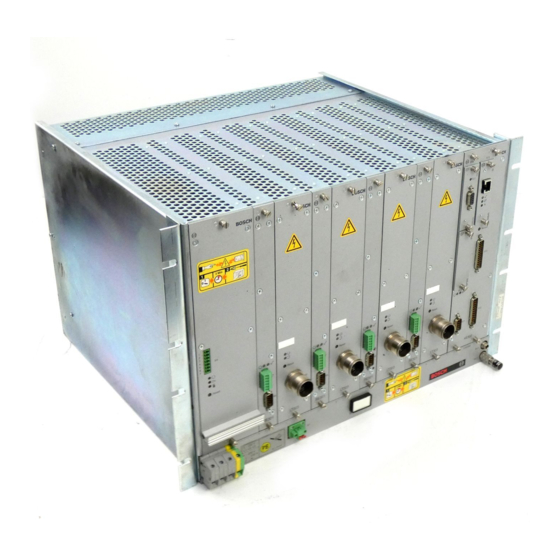
    3 609 929 721/1.2 | KE300 Electric Drives and Controls | Bosch Rexroth AG 5/52 4 Montagehinweis Montagehinweis Die Kommunikationseinheit ist in die dafür vorgesehenen Einschubschächte im Bau- gruppenträger BT300 einzuschieben. Vor dem Einschieben der Kommunikations- einheit muss der Bau- 3 Min gruppenträger BT300...
  • Seite 6: Inbetriebnahme

    6/52 Bosch Rexroth AG | Electric Drives and Controls KE300 | 3 609 929 721/1.2 5 Inbetriebnahme Inbetriebnahme Vor dem Einsetzen der Rexroth-Schnittstellen- Als Entladungsschutz der Batterie ist bei module muss der Bau- 3 Min Auslieferung zwischen Batterie und Federbü- gruppenträger BT300...
  • Seite 7 3 609 929 721/1.2 | KE300 Electric Drives and Controls | Bosch Rexroth AG 7/52 5 Inbetriebnahme Schnittstelle X 11: RS232 Die Schnittstelle X 11 dient dem Anschluss eines Programmiergerätes. Bild 5: SUB-D-Stecker, 25polig (male) Pin Signal Beschreibung/Funktion Bild 4:...
  • Seite 8: Schaltungsbeispiele Für Die Verwendung Der 20 Ma-Schnittstelle

    8/52 Bosch Rexroth AG | Electric Drives and Controls KE300 | 3 609 929 721/1.2 5 Inbetriebnahme 5.4.1 Schaltungsbeispiele für die Verwendung der 20 mA-Schnittstelle KE300 als aktiver Sender KE300 als passiver Sender KE300 KE300 10 V max. 7, 24 50 mA 100 Ω...
  • Seite 9 3 609 929 721/1.2 | KE300 Electric Drives and Controls | Bosch Rexroth AG 9/52 5 Inbetriebnahme Schnittstelle X 13: RS232/ 5.5.1 Schaltungsbeispiele für die Verwendung der RS 422 RS422 Die Schnittstelle X 13 ist für den Anschluss Empfänger Sender von z.
  • Seite 10: Steuersignale Der Ke300

    10/52 Bosch Rexroth AG | Electric Drives and Controls KE300 | 3 609 929 721/1.2 6 Steuersignale der KE300 Steuersignale der Schraubanwendung KE300 In einer KE können bis zu 48 Schraubanwen- dungen (ab Version V1.26) programmiert sein. Es können gleichzeitig bis zu 8 Schraubzelle Schraubanwendungen über die 8 zur Verfü-...
  • Seite 11: Steuersignale

    3 609 929 721/1.2 | KE300 Electric Drives and Controls | Bosch Rexroth AG 11/52 7 Beanstandungen und Reparaturen Steuersignale Service Über Steuersignale wird die Kommunikation Bosch Rexroth AG zwischen Schraubzelle und übergeordneter Competence Center Murrhardt Steuerung hergestellt. Die Steuersignale Service Schraub- und Einpress-Systeme sind über eine BMS-Zuordnungstabelle den...
  • Seite 12: Technical Data

    12/52 Bosch Rexroth AG | Electric Drives and Controls KE300 | 3 609 929 721/1.2 1 Technical Data Technical Data Designation KE300 Order number 0 608 830 162 Admissible ambient temperature 55 °C with ventilator Admissible relative humidity when in operation...
  • Seite 13: Mounting Instruction

    3 609 929 721/1.2 | KE300 Electric Drives and Controls | Bosch Rexroth AG 13/52 4 Mounting Instruction Mounting Instruction The communication unit must be inserted into the provided slide-in shafts of the card- rack BT300. Before inserting the communication unit,...
  • Seite 14: Initial Operation

    14/52 Bosch Rexroth AG | Electric Drives and Controls KE300 | 3 609 929 721/1.2 5 Initial Operation Initial Operation The modules must be inserted into the com- munication unit from the front and must be To protect the battery from running down, a...
  • Seite 15 3 609 929 721/1.2 | KE300 Electric Drives and Controls | Bosch Rexroth AG 15/52 5 Initial Operation Interface X 12: RS232/20 mA The interface X 12 is intended for connecting data collection terminals, bar code readers, etc. Functionality depends on the present func- tional scope of the firmware.
  • Seite 16 16/52 Bosch Rexroth AG | Electric Drives and Controls KE300 | 3 609 929 721/1.2 5 Initial Operation 5.4.1 Circuit Diagram Examples for the use of the 20 mA interface KE300 as active sender KE300 as passive sender KE300 KE300 10 V max.
  • Seite 17 3 609 929 721/1.2 | KE300 Electric Drives and Controls | Bosch Rexroth AG 17/52 5 Initial Operation Interface X 13: RS232/RS422 5.5.1 Circuit Diagram Examples for the use of RS 422 The interface X 13 is intended for connecting...
  • Seite 18: Steuersignale Der Ke300

    18/52 Bosch Rexroth AG | Electric Drives and Controls KE300 | 3 609 929 721/1.2 6 KE300 control signals KE300 control signals Tightening application Up to 48 tightening applications can be pro- grammed in a KE (from version V1.26). Up to...
  • Seite 19: Control Signals

    3 609 929 721/1.2 | KE300 Electric Drives and Controls | Bosch Rexroth AG 19/52 7 Complaints and repairs Control signals Service The tightening cell communicates with the Bosch Rexroth AG superior controller via control signals. A PLC Competence Center Murrhardt...
  • Seite 20: Caractéristiques Techniques

    20/52 Bosch Rexroth AG | Electric Drives and Controls KE300 | 3 609 929 721/1.2 1 Caractéristiques techniques Caractéristiques techniques Désignation KE300 N° de référence 0 608 830 162 Température ambiante autorisée lors du fonctionnement 55 °C avec ventilateur Humidité relative de l’air autorisée lors du fonctionnement 20 % à...
  • Seite 21: Instructions De Montage

    3 609 929 721/1.2 | KE300 Electric Drives and Controls | Bosch Rexroth AG 21/52 4 Instructions de montage Instructions de La batterie est superflue si on ne se sert pas de la fonction de sauvegarde. A cet effet, il montage faut déplacer le cavalier de «...
  • Seite 22: Mise En Service

    22/52 Bosch Rexroth AG | Electric Drives and Controls KE300 | 3 609 929 721/1.2 5 Mise en service Mise en service Pour des raisons de sécurité et de compati- bilité électromagnétique, il convient d’obturer Pour protéger la batterie contre un décharge- les logements de carte n’étant pas occupés...
  • Seite 23 3 609 929 721/1.2 | KE300 Electric Drives and Controls | Bosch Rexroth AG 23/52 5 Mise en service Interface X 11 : RS232 L’interface X 11 sert à raccorder un appareil de programmation. Fig. 5: Connecteur SUB-D, à 25 pôles (mâle)
  • Seite 24 24/52 Bosch Rexroth AG | Electric Drives and Controls KE300 | 3 609 929 721/1.2 5 Mise en service 5.4.1 Exemples de connexion pour l’utilisation de l’interface 20 mA KE300 comme émetteur actif KE300 comme émetteur passif KE300 KE300 10 V 7, 24 max.
  • Seite 25 3 609 929 721/1.2 | KE300 Electric Drives and Controls | Bosch Rexroth AG 25/52 5 Mise en service Interface X 13: RS232/RS422 5.5.1 Exemples de connexion pour l’utilisation de l’interface L’interface X 13 est prévue pour raccorder RS422 par ex. des appareils de saisie de données, des lecteurs de code-barres, etc.
  • Seite 26: Signaux De Commande Du Ke300

    26/52 Bosch Rexroth AG | Electric Drives and Controls KE300 | 3 609 929 721/1.2 6 Signaux de commande du KE300 Signaux de commande Application de vissage du KE300 Dans un KE, peuvent être programmées jus- qu’à 48 applications de vissage (à partir de la version V1.26).
  • Seite 27: Signaux De Commande

    3 609 929 721/1.2 | KE300 Electric Drives and Controls | Bosch Rexroth AG 27/52 7 Réclamations et réparations Signaux de commande Service Les signaux de commande permettent d’éta- Bosch Rexroth AG blir la communication entre les cellules de Competence Center Murrhardt vissage et la commande supérieure.
  • Seite 28: Dati Tecnici

    28/52 Bosch Rexroth AG | Electric Drives and Controls KE300 | 3 609 929 721/1.2 1 Dati Tecnici Dati Tecnici Code KE300 Codice d’ordinazione 0 608 830 162 Temperatura ambiente consentita in funzionamento 55 °C con ventilatore Umidità relativa consentita in funzionamento 20 % - 90 % senza condensazione Temperatura di magazzinaggio consentita –...
  • Seite 29: Istruzioni Di Montaggio

    3 609 929 721/1.2 | KE300 Electric Drives and Controls | Bosch Rexroth AG 29/52 4 Istruzioni di montaggio Istruzioni di montaggio L’unità di comunicazione deve essere intro- dotta negli appositi vani d’inserimento del rack BT300. Prima di inserire l’unità...
  • Seite 30: Messa In Funzione

    30/52 Bosch Rexroth AG | Electric Drives and Controls KE300 | 3 609 929 721/1.2 5 Messa in funzione Messa in funzione Prima d’inserire i mo- duli d’interfaccia Rex- Per evitare che la batteria si scarichi viene in- roth nel rack BT300...
  • Seite 31 3 609 929 721/1.2 | KE300 Electric Drives and Controls | Bosch Rexroth AG 31/52 5 Messa in funzione Interfaccia X 11: RS232 L’interfaccia X 11 è concepita per essere col- legata ad un dispositivo di programmazione. Figura 5: Connettore SUB-D, a 25 poli (maschio)
  • Seite 32 32/52 Bosch Rexroth AG | Electric Drives and Controls KE300 | 3 609 929 721/1.2 5 Messa in funzione 5.4.1 Esempi di circuito per l’impiego dell’interfaccia da 20 mA KE300 come trasmettitore attivo KE300 come trasmettitore passivo KE300 KE300 10 V mass.
  • Seite 33 3 609 929 721/1.2 | KE300 Electric Drives and Controls | Bosch Rexroth AG 33/52 5 Messa in funzione Interfaccia X 13: RS232/ 5.5.1 Esempi di circuito per l’impiego di RS422 RS422 L’interfaccia X 13 è stata concepita per la...
  • Seite 34: Segnali Di Comando Della Ke300

    34/52 Bosch Rexroth AG | Electric Drives and Controls KE300 | 3 609 929 721/1.2 6 Segnali di comando della KE300 Segnali di comando Applicazione di avvitamento della KE300 In una KE possono essere programmate fino a 48 applicazioni di avvitamento (a partire dalla versione V1.26).
  • Seite 35: Segnali Di Comando

    3 609 929 721/1.2 | KE300 Electric Drives and Controls | Bosch Rexroth AG 35/52 7 Reclami e riparazioni Segnali di comando Service Tramite i segnali di comando viene stabilita la Bosch Rexroth AG comunicazione tra cellula di avvitamento ed il Competence Center Murrhardt sistema sovraordinato.
  • Seite 36: Datos Técnicos

    36/52 Bosch Rexroth AG | Electric Drives and Controls KE300 | 3 609 929 721/1.2 1 Datos técnicos Datos técnicos Denominación KE300 Nº de ref. 0 608 830 162 Temperatura ambiental admisible durante el 55 °C con ventilador funcionamiento Humedad relativa del aire admisible durante el 20 % a 90 % sin condensación...
  • Seite 37: Instrucciones De Montaje

    3 609 929 721/1.2 | KE300 Electric Drives and Controls | Bosch Rexroth AG 37/52 4 Instrucciones de montaje Instrucciones de montaje Insertar la unidad de comunicación en los lu- gares de inserción previstos en el rack BT300. Antes de insertar la...
  • Seite 38: Puesta En Servicio

    38/52 Bosch Rexroth AG | Electric Drives and Controls KE300 | 3 609 929 721/1.2 5 Puesta en servicio Puesta en servicio Antes de insertar los módulos de interface Se suministra un aislador de papel como pro- Rexroth, el rack BT300 3 Min tección de descarga de la pila, que está...
  • Seite 39 3 609 929 721/1.2 | KE300 Electric Drives and Controls | Bosch Rexroth AG 39/52 5 Puesta en servicio Interface X 11: RS232 El interface X 11 sirve para conectar un equi- po de programación. Figura 5: Enchufe SUB-D, 25 polos (macho) Pin Señal...
  • Seite 40 40/52 Bosch Rexroth AG | Electric Drives and Controls KE300 | 3 609 929 721/1.2 5 Puesta en servicio 5.4.1 Ejemplos de conmutación para la utilización del interface 20 mA KE300 como emisor activo KE300 como emisor pasivo KE300 KE300...
  • Seite 41 3 609 929 721/1.2 | KE300 Electric Drives and Controls | Bosch Rexroth AG 41/52 5 Puesta en servicio Interface X 13: RS232/RS422 5.5.1 Ejemplos de conmutación para la utilización del RS422 El interface X 13 sirve para conectar p. ej., unidades de captación de datos, lectores de...
  • Seite 42: Señales De Control De La Ke300

    42/52 Bosch Rexroth AG | Electric Drives and Controls KE300 | 3 609 929 721/1.2 6 Señales de control de la KE300 Señales de control de Aplicación de atornillado la KE300 En una unidad de comunicación pueden pro- gramarse hasta 48 aplicaciones de atornilla- do (a partir de la versión V1.26).
  • Seite 43: Señales De Control

    3 609 929 721/1.2 | KE300 Electric Drives and Controls | Bosch Rexroth AG 43/52 7 Reclamaciones y reparaciones Señales de control Service La comunicación entre la célula de atornilla- Bosch Rexroth AG do y la unidad de control superior se estab- Competence Center Murrhardt lece mediante señales de mando.
  • Seite 44: Dados Técnicos

    44/52 Bosch Rexroth AG | Electric Drives and Controls KE300 | 3 609 929 721/1.2 1 Dados técnicos Dados técnicos Descrição KE300 Número para pedido 0 608 830 162 Temperatura ambiente permitida para operação 55 °C com ventilador Umidade relativa do ar permitida para operação 20 % até...
  • Seite 45: Instrução De Montagem

    3 609 929 721/1.2 | KE300 Electric Drives and Controls | Bosch Rexroth AG 45/52 4 Instrução de montagem Instrução de A bateria pode ser dispensada, quando a função de armazenamento não for usada. montagem Para tanto, a ponte de contato deve ser tirada de “Batt-active”...
  • Seite 46: Início De Operação

    46/52 Bosch Rexroth AG | Electric Drives and Controls KE300 | 3 609 929 721/1.2 5 Início de operação Início de operação Antes de colocar os módulos interface Rex- Para proteger contra a descarga da bateria, roth, o porta conjuntos 3 Min o equipamento é...
  • Seite 47 3 609 929 721/1.2 | KE300 Electric Drives and Controls | Bosch Rexroth AG 47/52 5 Início de operação Interface X 11: RS232 O interface X 11 serve para ligar um aparelho programador. Gravura 5: Plugue SUB-D, 25 pólos (male) Pino Sinal Descrição/Função...
  • Seite 48 48/52 Bosch Rexroth AG | Electric Drives and Controls KE300 | 3 609 929 721/1.2 5 Início de operação 5.4.1 Exemplos de circuitos de comando para o uso do interface 20 mA KE300 como transmissor ativo KE300 como transmissor passivo...
  • Seite 49 3 609 929 721/1.2 | KE300 Electric Drives and Controls | Bosch Rexroth AG 49/52 5 Início de operação Interface X 13: RS232/RS422 5.5.1 Exemplos de circuito de comando para o uso do O interface X 13 é destinado à ligação de, RS422 por ex., aparelhos de captação e registro de...
  • Seite 50: Sinais De Comando Da Ke300

    50/52 Bosch Rexroth AG | Electric Drives and Controls KE300 | 3 609 929 721/1.2 6 Sinais de comando da KE300 Sinais de comando da Aplicativo de parafusamento KE300 Pode haver até 48 aplicativos de parafusa- mento programados em uma KE (a partir da versão V1.26).
  • Seite 51: Reclamações E Reparações

    3 609 929 721/1.2 | KE300 Electric Drives and Controls | Bosch Rexroth AG 51/52 7 Reclamações e reparações Sinais de comando Assistência técnica A comunicação entre a célula de parafusa- Bosch Rexroth AG mento e um comando superior é feita através Competence Center Murrhardt de sinais de comando.
  • Seite 52 Bosch Rexroth AG Deutschland Electric Drives and Controls Schraub- und Einpress-Systeme Postfach 1161 D - 71534 Murrhardt Fax +49 (0) 71 92 22-1 81 e-mail: schraubtechnik@boschrexroth.de http://www.boschrexroth.com/schraubtechnik Ihr Vertragshändler Your authorized dealer Votre concessionnaire Su distribuidor autorizado Il Vostro concessionario Seu concessionário autorizado...

Inhaltsverzeichnis