
Verwandte Anleitungen für Siemens SIMOVERT MASTERDRIVES EB1


Inhaltszusammenfassung für Siemens SIMOVERT MASTERDRIVES EB1
- Seite 1 All manuals and user guides at all-guides.com Betriebsanleitung SIMOVERT MASTERDRIVES Operating Instructions EB1 - Expansion Board 1 Ausgabe / Edition: AA 477 791 4070 76 J AA-74...
- Seite 2 However, the information in this document is regularly checked and necessary corrections will be included in subsequent editions. We are grateful for any recommendations for improvement. SIMOVERT® Registered Trade Mark © Siemens AG 1997 All rights reserved...
-
Seite 3: Inhaltsverzeichnis
All manuals and user guides at all-guides.com EB1 - Expansion Board 1 Inhaltsverzeichnis Inhaltsverzeichnis Definitionen und Warnungen..................0-1 Beschreibung ......................... 1-1 Technische Daten ......................2-1 Montage .......................... 3-1 Anschließen........................4-1 Inbetriebsetzung ......................5-1 Siemens AG 477 791 4070 76 J AA-74 SIMOVERT MASTERDRIVES Betriebsanleitung... - Seite 4 All manuals and user guides at all-guides.com...
-
Seite 5: Definitionen Und Warnungen
Sinne der Dokumentation bzw. der Warnhinweise auf dem Produkt selbst WARNUNG bedeutet, daß Tod, schwere Körperverletzung oder erheblicher Sachschaden eintreten können, wenn die entsprechenden Vorsichtsmaßnahmen nicht getroffen werden. Siemens AG 477 791 4070 76 J AA-74 SIMOVERT MASTERDRIVES Betriebsanleitung... - Seite 6 ♦ Dieses Personal muß gründlich mit allen Warnungen und Instand - haltungsmaßnahmen gemäß dieser Dokumentation vertraut sein. ♦ Der einwandfreie und sichere Betrieb dieses Gerätes setzt sachgemäßen Transport, fachgerechte Lagerung, Montage und Installation sowie sorgfältige Bedienung und Instandhaltung voraus. 477 791 4070 76 J AA-74 Siemens AG Betriebsanleitung SIMOVERT MASTERDRIVES...
- Seite 7 Kunststoff- oder Metallbehältern) aufbewahrt oder versandt werden. ♦ Soweit Verpackungen nicht leitend sind, müssen Baugruppen vor dem Verpacken leitend verhüllt werden. Hier kann z. B. leitender Schaumstoff oder Haushalts-Alufolie verwendet werden. Siemens AG 477 791 4070 76 J AA-74 SIMOVERT MASTERDRIVES Betriebsanleitung...
- Seite 8 ♦ b = EGB-Tisch ♦ c = EGB-Schuhe ♦ d = EGB-Mantel ♦ e = EGB-Armband ♦ f = Erdungsanschluß der Schränke Sitzplatz Stehplatz Steh- / Sitzplatz Bild 0-1 EGB-Schutzmaßnahmen 477 791 4070 76 J AA-74 Siemens AG Betriebsanleitung SIMOVERT MASTERDRIVES...
-
Seite 9: Beschreibung
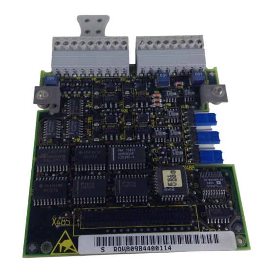
♦ 1 Analogeingang mit Differenzsignal, verwendbar als Strom- und Spannungseingang ♦ 2 Analogeingänge (single ended), die auch als Digitaleingänge verwendbar sind ♦ 2 Analogausgänge ♦ 1 Anschluß für die externe 24 V-Spannungsversorgung für die Digitalausgänge Siemens AG 477 791 4070 76 J AA-74 SIMOVERT MASTERDRIVES Betriebsanleitung... - Seite 10 All manuals and user guides at all-guides.com Beschreibung EB1 - Expansion Board 1 Befestigungs- schraube 64poliger Systemstecker X480 Jumper X486, X487, X488 X481 Befestigungs- schraube Bild 1-1 Ansicht der Optionsbaugruppe EB1 477 791 4070 76 J AA-74 Siemens AG Betriebsanleitung SIMOVERT MASTERDRIVES...
-
Seite 11: Technische Daten
-25° C bis +70° C (-13° F bis 158° F) Relative Luftfeuchtigkeit ≤ 95 % bei Transport und Lagerung zulässige Feuchtebeanspruchung ≤ 85 % im Betrieb (Betauung nicht zulässig) Tabelle 2-1 Allgemeine technische Daten Siemens AG 477 791 4070 76 J AA-74 SIMOVERT MASTERDRIVES Betriebsanleitung... - Seite 12 (+ 13 V ... + 33 V) Spannungsbereich HIGH • 4 kΩ Eingangswiderstand Als Ausgang • offen Spannungsbereich LOW • > P24 ext. -2,5 V / 100 mA Spannungsbereich HIGH 477 791 4070 76 J AA-74 Siemens AG Betriebsanleitung SIMOVERT MASTERDRIVES...
- Seite 13 AO1, AO2, AOM Strom- oder Spannungssignal • ± 10,0 V / ± 5 mA Spannungsbereich • Hardwareglättung 10 µs • 11 Bit + Vorzeichen Auflösung Tabelle 2-2 technische Daten der EB1 Siemens AG 477 791 4070 76 J AA-74 SIMOVERT MASTERDRIVES Betriebsanleitung...
- Seite 14 All manuals and user guides at all-guides.com...
-
Seite 15: Montage
Grundsätzlich können Sie die Optionsbaugruppe EB1 in jeden Slot einbauen. Beachten Sie aber, daß eine Geberbaugruppe immer den Slot C benötigt. Pro Gerät können maximal zwei EB1 gesteckt werden. Siemens AG 477 791 4070 76 J AA-74 SIMOVERT MASTERDRIVES Betriebsanleitung... - Seite 16 All manuals and user guides at all-guides.com...
-
Seite 17: Anschließen
24 V / 4 k Ω (Eingang) 24 V / 100 mA (Ausgang) 24 V 4 bidirektionale Digitalein-/ausgänge 24 V 3 Digitaleingänge 24 V / 4 k Ω Bild 4-1 Anschlußübersicht X480 Siemens AG 477 791 4070 76 J AA-74 SIMOVERT MASTERDRIVES Betriebsanleitung... - Seite 18 ±10 V ±20 mA 2 Analogeingänge (single ended) 13 Bit + VZ +/- 10 V / 40 k Ω auch als Digitaleingänge verwendbar Schaltschwelle 8 V Bild 4-2 Anschlußübersicht X481 477 791 4070 76 J AA-74 Siemens AG Betriebsanleitung SIMOVERT MASTERDRIVES...
- Seite 19 Die Masseleitungen sind mit einer Drossel geschützt. Klemme 46 befindet sich im eingebauten Zustand oben. Tabelle 4-1 Klemmenbelegung Anschluß X480 Die externe 24 V-Versorgung muß für die Ströme der Digitalausgänge HINWEIS ausgelegt werden. Siemens AG 477 791 4070 76 J AA-74 SIMOVERT MASTERDRIVES Betriebsanleitung...
- Seite 20 Analogeingang 3 Masse Analogeingang anschließbarer Querschnitt: 1,5 mm² (AWG 16) Die Masseleitungen sind mit einer Drossel geschützt Klemme 47 befindet sich im eingebauten Zustand oben. Tabelle 4-2 Klemmenbelegung Anschluß X481 477 791 4070 76 J AA-74 Siemens AG Betriebsanleitung SIMOVERT MASTERDRIVES...
- Seite 21 Brücke 2 + 3 Analogeingang X488 Umschaltung Strom-/ Spannungseingang an AI1P, AI1N • Brücke 1 + 2 • Stromeingang • Brücke 2 + 3 • Spannungseingang Tabelle 4-3 Jumpereinstellungen Siemens AG 477 791 4070 76 J AA-74 SIMOVERT MASTERDRIVES Betriebsanleitung...
- Seite 22 All manuals and user guides at all-guides.com...
-
Seite 23: Inbetriebsetzung
Beachten Sie bitte, daß bei zwei gesteckten Klemmenerweiterungen EB1 für HINWEISE jede Baugruppe ein eigener Parametersatz vorgesehen ist. Weitere Informationen für die Parametrierung der Klemmenerweiterung EB1 entnehmen Sie bitte dem Kompendium. Siemens AG 477 791 4070 76 J AA-74 SIMOVERT MASTERDRIVES Betriebsanleitung... - Seite 24 All manuals and user guides at all-guides.com...
- Seite 25 All manuals and user guides at all-guides.com EB1 - Expansion Board 1 Contents Contents Definitions and Warnings ......................0-1 Description ........................... 1-1 Technical Data ..........................2-1 Installation............................ 3-1 Connecting-up ..........................4-1 Start-up ............................5-1 Siemens AG 477 791 4070 76 J AA-74 SIMOVERT MASTERDRIVES Operating Instructions...
- Seite 26 All manuals and user guides at all-guides.com...
-
Seite 27: Definitions And Warnings
For the purpose of this documentation and the product warning labels, WARNING "Warning" indicates death, severe personal injury or property damage can result if proper precautions are not taken . Siemens AG 477 791 4070 76 J AA-74 SIMOVERT MASTERDRIVES Operating Instructions... - Seite 28 ♦ The successful and safe operation of this equipment is dependent on correct transport, proper storage and installation as well as careful operation and maintenance. 477 791 4070 76 J AA-74 Siemens AG Operating Instructions SIMOVERT MASTERDRIVES...
- Seite 29 (e.g. metalized plastic boxes or metal containers). ♦ If the packing material is not conductive, the boards must be wrapped with a conductive packaging material, e.g. conductive foam rubber or household aluminium foil. Siemens AG 477 791 4070 76 J AA-74 SIMOVERT MASTERDRIVES Operating Instructions...
- Seite 30 ♦ c = ESD shoes ♦ d = ESD overall ♦ e = ESD chain ♦ f = Cubicle ground connection Sitting Standing Standing / Sitting Fig. 0-1 ESD protective measures 477 791 4070 76 J AA-74 Siemens AG Operating Instructions SIMOVERT MASTERDRIVES...
-
Seite 31: Description
♦ 2 analog inputs (single-ended), which can also be used as digital inputs ♦ 2 analog outputs ♦ 1 connection for the external 24 V voltage supply for the digital outputs Siemens AG 477 791 4070 76 J AA-74 SIMOVERT MASTERDRIVES Operating Instructions... - Seite 32 All manuals and user guides at all-guides.com Description EB1 - Expansion Board 1 Fixing screw 64-pole system connector X480 Jumper X486, X487, X488 X481 Fixing screw Fig. 1-1 View of the EB1 optional board 477 791 4070 76 J AA-74 Siemens AG Operating Instructions SIMOVERT MASTERDRIVES...
-
Seite 33: Technical Data
-25° C to +70° C (-13° F to 158° F) ≤ 95 % during transport and storage Permissible humidity rating Relative air humidity ≤ 85 % in operation (condensation not permissible) Table 2-1 General technical data Siemens AG 477 791 4070 76 J AA-74 SIMOVERT MASTERDRIVES Operating Instructions... - Seite 34 (+ 13 V ... + 33 V) Voltage range HIGH • 4 kΩ Input resistance As output • open Voltage range LOW • > P24 ext. -2.5 V / 100 mA Voltage range HIGH 477 791 4070 76 J AA-74 Siemens AG Operating Instructions SIMOVERT MASTERDRIVES...
- Seite 35 Current or voltage signal • ± 10.0 V / ± 5 mA Voltage range • Hardware smoothing 10 µs • 11 bit + sign Resolution Table 2-1 Technical data of EB1 Siemens AG 477 791 4070 76 J AA-74 SIMOVERT MASTERDRIVES Operating Instructions...
- Seite 36 All manuals and user guides at all-guides.com...
-
Seite 37: Installation
Generally, you can install the EB1 optional board in every slot. However, bear NOTE in mind that a sensor board always requires slot C. A maximum of two EB1s can be installed per unit. Siemens AG 477 791 4070 76 J AA-74 SIMOVERT MASTERDRIVES Operating Instructions... - Seite 38 All manuals and user guides at all-guides.com...
-
Seite 39: Connecting-Up
24 V / 100 mA (output) 24 V 4 bidirectional digital inputs/outputs 24 V 3 digital inputs 24 V / 4 k Ω Fig. 4-1 X480 connection overview Siemens AG 477 791 4070 76 J AA-74 SIMOVERT MASTERDRIVES Operating Instructions... - Seite 40 2 analog inputs (single-ended) 13 bit + sign +/- 10 V / 40 k Ω Can also be used as digital inputs Switching threshold 8 V Fig. 4-2 X481 connection overview 477 791 4070 76 J AA-74 Siemens AG Operating Instructions SIMOVERT MASTERDRIVES...
- Seite 41 Terminal 46 is at the top when installed. Table 4-1 Terminal assignment at connection X480 The external 24 V supply must be sized for the currents of the digital outputs. NOTE Siemens AG 477 791 4070 76 J AA-74 SIMOVERT MASTERDRIVES Operating Instructions...
- Seite 42 Connectable cross-section: 1.5 mm² (AWG 16) The ground cables are protected by a reactor. Terminal 47 is at the top when installed. Table 4-2 Terminal assignment at connection X481 477 791 4070 76 J AA-74 Siemens AG Operating Instructions SIMOVERT MASTERDRIVES...
- Seite 43 Analog input X488 Current/voltage input switchover at AI1P, AI1N • • Jumper 1 + 2 Current input • • Jumper 2 + 3 Voltage input Table 4-3 Jumper settings Siemens AG 477 791 4070 76 J AA-74 SIMOVERT MASTERDRIVES Operating Instructions...
- Seite 44 All manuals and user guides at all-guides.com...
-
Seite 45: Start-Up
Please bear in mind that if two EB1 terminal expansions are installed, each NOTES board is provided with its own parameter set. Please refer to the Compendium for further information regarding parameterization of the EB1 terminal expansion board. Siemens AG 477 791 4070 76 J AA-74 SIMOVERT MASTERDRIVES Operating Instructions... - Seite 46 Definitions and warnings 11.97 Beschreibung Description 11.97 Technische Daten Technical Data 11.97 Montage Installation 11.97 Anschließen Connecting-up 11.97 Inbetriebsetzung Start-up 11.97 Automation und Drives Drehzahlveränderbare Antriebe Postfach 3269, D-91050 Erlangen Siemens Aktiengesellschaft Änderungen vorbehalten Printed in the federal Republic of Germany 11.97...