Herunterladen Inhalt Inhalt Diese Seite drucken
Sentiotec PHÖNIX-S Benutzerhandbuch
Vorschau ausblenden Andere Handbücher für PHÖNIX-S:

Werbung

Verfügbare Sprachen

Verfügbare Sprachen

Benutzerhandbuch
DE
Infrarotkabine
PHÖNIX-S (1-030-313)
 1/12
06/2020

Werbung

Inhaltsverzeichnis
loading

Inhaltszusammenfassung für Sentiotec PHÖNIX-S

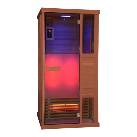
  • Seite 1 Benutzerhandbuch Infrarotkabine PHÖNIX-S (1-030-313)  1/12 06/2020...
  • Seite 2 EINLEITUNG Vielen Dank, dass Sie sich für unser Produkt entschieden haben. Bitte lesen Sie dieses Handbuch vor der Montage sorgfältig durch und bewahren Sie es auf. Schreiben Sie sich die Seriennummer der Kabine am Schaltkasten auf, da diese Nummer bei Reparaturen oder der Bestellung von Ersatzteilen erforderlich ist.
  • Seite 3: Einzelteile Der Kabine (Abweichungen Möglich)

    TEILELISTE Einzelteile der Kabine (Abweichungen möglich) NAME MENGE Bodenplatte (1020 x 998 x 65 mm) Rückwand (1927 x 940 x 43 mm) Seitenwand 1 (1927 x 593 x 33 mm) Seitenwand 2 (1927 x 593 x 33 mm) Seitenglas (1896 x 344 x 6 mm) Türpfosten (1927 x 70 x 43 mm) Vorderwand mit Glas (1927 x 344 x 48 mm) Deckenplatte (1020 x 998 x 65 mm)
  • Seite 4: Hinweise Zur Montage

    Zubehörteile (Abweichungen möglich) Gummistreifen Φ 3 x 16 Φ 4 x 45 Φ 6 x 60 30 x 20 x 2 10 m 1 Stk. 33 Stk. 2 Stk. 1 Stk. MONTAGEANLEITUNG Hinweise zur Montage Entfernen Sie die Transportverpackung und prüfen Sie vor der Montage, ob die Infrarotkabine vollständig und in einwandfreiem Zustand geliefert wurde.
  • Seite 5 MONTAGEANLEITUNG Montageschritte Hinweis: Rückwand verfügt über Lüftungsschlitze; 5 cm Abstand zur Wand einhalten Hinweis: Hinweis: Schließen Sie das etwa 20 mm von der Kabel für das Waden- Bankplatte entfernt Heizelement an. 4-Φ4*45  5/12...
  • Seite 6 MONTAGEANLEITUNG Montageschritte  6/12...
  • Seite 7 MONTAGEANLEITUNG Montageschritte Steuerung Netzteil Gummi- streifen Griff Glastür Griff Hinweis: Schließen Sie alle Kabel auf dem Dach der Kabine an  7/12...
  • Seite 8 SCHALTPLAN Farbleuchte Bedienteil Steuerung Leistungsteil Waden Vorder- seite Rück- seite  8/12...
  • Seite 9: Temperatureinstellungen

    BEDIENUNGSANLEITUNG Verbinden Sie die Leistungseinheit mit der Wandsteckdose. Auf dem Display beginnt die LED-Anzeige zu blinken. Nun können die Infrarotheizelemente, die Leuchte und die Musikfunktion eingeschaltet werden. 1) Inbetriebnahme Drücken Sie auf , um die Kabine einzuschalten. Die Heizelemente beginnen zu heizen.
  • Seite 10 SERVICE Gebrauchsanleitung Trinken Sie viel Flüssigkeit vor und nach der Verwendung der Infrarotkabine. Trocknen Sie sich vollständig ab. Die optimale Kabinentemperatur für eine angenehme Sitzung liegt zwischen 35 und 40 °C. Spätestens nach einer Heizzeit von einer Stunde sollte die Kabine ausgeschaltet und eine Heizpause von mindestens 30 Minuten eingelegt werden.
  • Seite 11 SERVICE GARANTIEKARTE Füllen Sie dieses Formular aus, fotografieren/scannen Sie es, und senden Sie es per E-Mail an: ______________________________________________ Kaufdatum: ____________________________________ Steuergerätetikett Seriennummer: _________________________________ Referenznummer: _______________________________ Name: ________________________________________ Artikelzustand (ungeöffnet, vor Kurzem geöffnet oder gebraucht): ____________________________________ Kennzeichnen Sie in der folgenden Abbildung (mit einem Kreis), welches Heizelement oder welche Platte fehlerhaft ist.
  • Seite 12 GmbH | Division of Harvia Group | Wartenburger Straße 31, A-4840 Vöcklabruck T +43 (0) 7672/22 900-50| F -80 | info@sentiotec.com | www.sentiotec.com  12/12...
  • Seite 13 User´s manual Infrared Cabin PHÖNIX-S (1-030-313)  1/12 06/2020...
  • Seite 14: Technical Data

    PREFACE Thank you very much for purchasing our product. Please read this manual carefully before assembling and save it afterwards. Please write down the control box serial number of the cabin as this number will be required in case of repair or order of spare parts. ATTENTION Installation and repair should only be done by a qualified electrician! Check power supply rating and make sure the grounded outlet is correctly connected before installation.
  • Seite 15: Parts List

    PARTS LIST Cabin Individual parts (variations possible) NAME Q’TY Floor panel (1020*998*65mm) Back panel (1927*940*43mm) Side panel 1 (1927*593*33mm) Side panel 2 (1927*593*33mm) Side glass (1896*344*6mm) Door jamb (1927*70*43mm) Front panel with glass (1927*344*48mm) Toppanel (1020*998*65mm) Bench support panel (898*468*33mm) Bench surface panel (900*500*33mm) Guardrail 1 (898*650*54mm) Guardrail 2 (650*260*54mm)
  • Seite 16 Hardware parts (variations possible) Rubber strip Φ3*16 Φ4*45 Φ6*60 30*20*2 ASSEMBLE INSTRUCTIONS Assemble tips Please remove transport packaging and inspect that your infrared cabin has been delivered complete and intact before beginning assemble. A least 2 persons are required for assemble of the cabin Please check the countersink and hole diameter of the drill holes to avoid damaging the wood.
  • Seite 17 ASSEMBLE INSTRUCTIONS Assemble steps Note: back panel has ventilation slits must keep 5 cm away from the next wall Note: Note: about 20mm away connect calves from the bench panel heater cable 4-Φ4*45  5/12...
  • Seite 18 ASSEMBLE INSTRUCTIONS Assemble steps  6/12...
  • Seite 19 ASSEMBLE INSTRUCTIONS Assemble steps Note: connect all cables on the roof of the cabin  7/12...
  • Seite 20: Circuit Diagram

    CIRCUIT DIAGRAM  8/12...
  • Seite 21: Temperature Settings

    OPERATING INTRUCTIONS Connect the power unit to wall outlet, the LED indicator will start to blink on the display. Now it is possible to switch on the infrared heaters, the light and the music function. 1) Startup Press to switch on the cabin and heaters start to work, the length of time is automatically set to 99 minutes and the air temperature inside the cabin will be displayed.
  • Seite 22: Use Instructions

    SERVICE Use instructions Drink plenty of liquids before and after use of the infrared cabin. Dry yourself off completely. The optimal cabin temperature for a pleasant session lies between 35 and 40°C. After a heating period of an hour at the latest, the cabin should be switched off and a heating brake of at least 30 minutes should be taken.
  • Seite 23: Guarantee Card

    SERVICE GUARANTEE CARD Fill in this form and make a picture of it and Email to: ______________________________________________ Date of purchase: _______________________________ Serial Number: _________________________________ Control unit label Reference number: ______________________________ Name: ________________________________________ Article state (unopened, just opened or used): ________ Please encircle on picture below which heater or which panel has a fault.
  • Seite 24 GmbH | Division of Harvia Group | Wartenburger Straße 31, A-4840 Vöcklabruck T +43 (0) 7672/22 900-50| F -80 | info@sentiotec.com | www.sentiotec.com  12/12...
  • Seite 25: Käyttäjän Käsikirja

    Käyttäjän käsikirja Infrapunasauna PHÖNIX-S (1-030-313)  1/12 06/20...
  • Seite 26: Tekniset Tiedot

    JOHDANTO Hienoa, kun valitsit tuotteemme. Lue tämä käsikirja huolellisesti ennen asennusta ja säilytä se tulevaa käyttöä varten. Kirjoita muistiin saunan sarjanumero kytkentäkotelosta, koska voit tarvita tätä korjausten tai varaosien tilauksen yhteydessä. HUOMIO Ainoastaan sähköalan ammattilainen saa suorittaa asennuksen ja korjaustöitä! Varmista sähkösyötön teho sekä...
  • Seite 27 OSALUETTELO Saunan yksittäisosat (mahdollisia poikkeuksia) NRO NIMI MÄÄRÄ Lattialevy (1020 x 998 x 65 mm) Takaseinä (1927 x 940 x 43 mm) Sivuseinä 1 (1927 x 593 x 33 mm) Sivuseinä 2 (1927 x 593 x 33 mm) Sivulasi (1896 x 344 x 6 mm) Ovilista (1927 x 70 x 43 mm) Etuseinä...
  • Seite 28 Lisävarusteet (mahdollisia poikkeuksia) Kumilista Φ 3 x 16 Φ 4 x 45 Φ 6 x 60 30 x 20 x 2 10 m 1 kpl 33 kpl 2 kpl 1 kpl ASENNUSOHJE Ohjeita asennukseen Poista kuljetuspakkaus ja tarkasta ennen asennusta, että infrapunasauna toimitettiin täydellisenä ja moitteettomassa kunnossa.
  • Seite 29 ASENNUSOHJE Asennusvaiheet Huomautus: Takaseinässä on tuuletusaukkoja; pidä 5 cm:n etäisyys seinään Huomautus: Huomautus: noin 20 mm Liitä pohjelämmitys laudelevystä poispäin vastuksen kaapeli. 4-Φ4*45  5/12...
  • Seite 30 ASENNUSOHJE Asennusvaiheet  6/12...
  • Seite 31 ASENNUSOHJE Asennusvaiheet Tehoyksikkö Virtalähde Kumilista Kahva Lasiovi Kahva Huomautus: Liitä kaikki kaapelit saunan kattoon  7/12...
  • Seite 32 Kytkentäkaavio Värivalo Ohjauspaneeli Tehoyksikkö Pohkeet Etuosa Takaosa  8/12...
  • Seite 33 KÄYTTÖOHJE Liitä tehoyksikkö seinäpistorasiaan. Näytön LED-valo alkaa vilkkua. Nyt voit käynnistää infrapunalämmitysvastukset, valon ja musiikkitoiminnon. 1) Käyttöönotto Kytke sauna päälle painamalla painiketta . Lämmitysvastukset aloittavat lämmityksen. Kesto säädetään automaattisesti 99 minuuttiin ja saunan ilmalämpötila tulee näkyviin. Kytke lämmitysvastukset pois painamalla painiketta uudelleen.
  • Seite 34 HUOLTO Käyttöohje Juo paljon nestettä, ennen kuin menet saunaan sekä sen jälkeen. Kuivaa itsesi huolellisesti. Saunan optimaalinen lämpötila mukavaa oleskelua varten on 35 ja 40 °C:een välissä. Sauna tulee kytkeä pois viimeistään tunnin lämmitysajan jälkeen ja pitää vähintään 30 minuutin lämmitystauko. Suosittelemme, että...
  • Seite 35 HUOLTO TAKUUKORTTI Täytä tämä lomake, valokuvaa tai skannaa se ja lähetä sähköpostilla osoitteeseen: ______________________________________________ Ostopäivämäärä: ________________________________ Ohjauskeskuksen etiketti Sarjanumero: ___________________________________ Viitenumero: ___________________________________ Nimi: _________________________________________ Tuotteen tila (avaamaton, hiljattain avattu tai käytetty): ___________________________________ Merkitse seuraavaan kuvaan (ympyrällä) mikä lämmitysvastus tai mikä levy on kyseessä. Lisää...
  • Seite 36 GmbH | Division of Harvia Group | Wartenburger Straße 31, A-4840 Vöcklabruck T +43 (0) 7672/22 900-50| F -80 | info@sentiotec.com | www.sentiotec.com  12/12...

Diese Anleitung auch für:

1-030-313

Inhaltsverzeichnis