Herunterladen Inhalt Inhalt Diese Seite drucken
Inhaltsverzeichnis

Werbung

Verfügbare Sprachen
  • DE

Verfügbare Sprachen

  • DEUTSCH, seite 1
Massivsauna
ALASKA
MINI
160 x 110 x 204 cm
MONTAGEANLEITUNG
Deutsch
Version 07/18
ALASKA-MN
Artikel-Nr. 1-030-270
DE
EN
FR
IT
PL
PT

Werbung

Inhaltsverzeichnis
loading

Inhaltszusammenfassung für Sentiotec ALASKA-MN

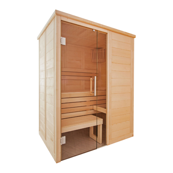
  • Seite 1 Massivsauna ALASKA MINI 160 x 110 x 204 cm MONTAGEANLEITUNG Deutsch ALASKA-MN Version 07/18 Artikel-Nr. 1-030-270...
  • Seite 2: Inhaltsverzeichnis

    Inhaltsverzeichnis 1. Montage Vorbereitung 1.1. Benötigtes Werkzeug 1.2. Wartung und Reinigung 1.3. Entsorgung 1.4. Stückliste ALASKA MINI 2. Montage der Kabine 2.1. Montage des Bodenrahmens 2.2. Montage der Wandelemente 2.3. Montage Dach 2.4. Montage Lüftungsschieber 2.5. Montage Inneneinrichtung 2.6. Montage Zubehör 2.7.
  • Seite 3: Montage Vorbereitung

    Lesen Sie diese Montageanleitung gut durch und bewahren Sie sie in der Nähe der Sauna auf. So können Sie jederzeit Produktinformationen nachlesen. Sie finden diese Montageanleitung auch im Downloadbereich unserer Webseite auf www.sentiotec.com/downloads. Wichtige Hinweise: ● Kontrollieren Sie, bevor Sie mit der Arbeit beginnen, anhand der Stückliste, ob alle Einzelteile auch tatsächlich mitgeliefert wurden.
  • Seite 4: Benötigtes Werkzeug

    Montageanleitung S. 4/34 1.1. Benötigtes Werkzeug ● Hammer und Beilageholz oder einen Gummihammer ● Akkuschrauber mit Bits für Kreuzschrauben und Torx ● Rollmaßband ● Bohrer mit Durchmesser 3 mm, 10 mm, 20 - 30 mm (für Stromkabel Saunaofen) ● Wasserwaage ●...
  • Seite 5: Wartung Und Reinigung

    Montageanleitung S. 5/34 1.2. Wartung und Reinigung ● Die Sauna sollte mit einem feuchten Tuch gereinigt werden. Verwenden Sie nur warmes Wasser - keine Reinigungsmittel. ● Wird die Sauna längere Zeit nicht benutzt, empfehlen wir, die Kabine einmal im Monat aufzuheizen. Harzgallen sind kein Reklamationsgrund.
  • Seite 6: Stückliste Alaska Mini

    Montageanleitung S. 6/34 1.4. Stückliste ALASKA MINI Az Bezeichnung Maß Bodenrahmen 1 Bodenrahmen 156 x 9 x 4 cm 1 Bodenrahmen 108 x 9 x 4 cm 1 Bodenrahmen 102 x 9 x 4 cm 1 Bodenrahmen 64 x 9 x 4 cm Wandelemente 1 Lüftungselement A/B mit Multiclip 193 x 48 x 4 cm...
  • Seite 7 Montageanleitung S. 7/34 Az Bezeichnung Maß Inneneinrichtung 1 Bank 147 x 62 x 9 cm 1 Fußauftrittplatte 80 x 35 x 9 cm 2 Fußauftritt Füße 43 x 33 x 4 cm 2 Fußauftritt Strebe, 2 x 45º schräg 49,5 x 8 x 2 cm 1 Rückenlehne 138 x 26 x 4 cm 1 Banksichtblende...
  • Seite 8: Montage Der Kabine

    Montageanleitung S. 8/34 2. Montage der Kabine Die Kabine kann „rechts“ oder „links“ aufgebaut werden, beachten Sie dazu die Grundrisspläne auf Seite 30 und Seite 31. 2.1. Montage des Bodenrahmens 156 cm Grundriss „rechts“ 64 cm Bohrer 3mm, 3 Stk. Schrauben 4 x 70 mm 156 cm Grundriss „links“...
  • Seite 9: Montage Der Wandelemente

    Montageanleitung S. 9/34 2.2. Montage der Wandelemente Die Ecksteher werden mittels „Multiclips“ mit den Wandelementen verbunden. Die weiteren Wandelemente sind mit Nut und Feder verbunden und werden miteinander verschraubt. A bezeichnet immer die Sichtseite, dies ist auf der Oberseite der Wand- elemente gekennzeichnet.
  • Seite 10 Montageanleitung S. 10/34 Montage Ecksteher mit Wandelement Montieren Sie die Wandelemente mit den Eckstehern am Boden vor und setzen Sie diese Ecken dann auf den Bodenrahmen auf. Stecken Sie den Ecksteher von oben nach unten auf die Wandelemente. Achten Sie dabei auf die korrekte Ausrichtung der „Multiclips“ (siehe unten). Der Eck- steher muss bündig mit den Wandelementen sein.
  • Seite 11 Montageanleitung S. 11/34 Montage Wandelemente Das Elektroelement hat Bohrungen zum Verlegen der Kabel. Position siehe Grundrisspläne auf Seite 30 und Seite 31. Elektroelement...
  • Seite 12 Montageanleitung S. 12/34 Verschrauben der Wandelemente Überprüfen Sie die rechten Winkel, bevor Sie die Wandelemente verschrauben. Beachten Sie den Tipp auf Seite 4. Bohrer 3 mm, 4 Stk. Schrauben 4 x 70 mm...
  • Seite 13 Montageanleitung S. 13/34 Ecksteher und Steher für Glas...
  • Seite 14 Montageanleitung S. 14/34 Glaselement Element oberhalb der Tür Das Element für Grundriss „rechts“ auswählen...
  • Seite 15 Montageanleitung S. 15/34 Bohrer 3 mm, 2 Stk. Schrauben 4 x 70 mm...
  • Seite 16: Montage Dach

    Montageanleitung S. 16/34 2.3. Montage Dach Dachauflageleisten 4 cm Bohrer 3 mm, 12 Stk. Schrauben 4 x 70 mm...
  • Seite 17 Montageanleitung S. 17/34 Dachelemente Bohrer 3 mm, 10 Stk. Schrauben 4 x 70 mm...
  • Seite 18: Montage Lüftungsschieber

    Montageanleitung S. 18/34 2.4. Montage Lüftungsschieber Bohrer 3 mm, 4 Stk. Schrauben 3 x 40 mm 2.5. Montage Inneneinrichtung Bankauflageleisten Bohrer 3 mm, 3 Stk. Schrauben 5 x 70 mm 2 Stk. Schrauben 4 x 60 mm...
  • Seite 19 Montageanleitung S. 19/34 Bohrer 3 mm, 3 Stk. Schrauben 5 x 70 mm Schrauben 4 x 60 mm...
  • Seite 20 Montageanleitung S. 20/34 Banksichtblende 4 Stk. Schrauben 4 x 60 mm Bank...
  • Seite 21 Montageanleitung S. 21/34 Fußauftritt 6 Stk. Schrauben 4 x 70 mm...
  • Seite 22 Montageanleitung S. 22/34 4 Stk. Schrauben 3,5 x 35 mm...
  • Seite 23 Montageanleitung S. 23/34 Rückenlehne Bohrer 3 mm, 3 Stk. Schrauben 3 x 40 mm ca. 5 cm ca. 5 cm ca. 25 cm...
  • Seite 24: Montage Zubehör

    Montageanleitung S. 24/34 2.6. Montage Zubehör Saunaleuchte Leuchtmittel einsetzen (nicht im Lieferumfang enthalten) Bohrer 3 mm, 2 Stk. Schrauben 4 Stk. Schrauben 3 x 40 mm...
  • Seite 25 Montageanleitung S. 25/34 Ofenschutzgitter Bohren Sie vor der Montage des Ofenschutzgitters den Auslass für das Ofenkabel im Elektroelement. 12 Stk. Schrauben 3 x 40 mm Ofenschutzgitter individuell kürzbar...
  • Seite 26: Montage Glastür

    Montageanleitung S. 26/34 2.7. Montage Glastür Die untere Bohrung des Türgriffs ist in 92,4 cm Höhe. Die Ausrichtung der Beschläge wird durch die Justierung / Drehung der beiden Kunststoffeinlagen vorgenommen.
  • Seite 27 Montageanleitung S. 27/34 Türgriff und Überschubblech Die Türgriffe werden von innen miteinander verschraubt. Silikonring in Bohrungen einlegen Kunststoff-Beilagscheiben bei Niro-Griff beilegen...
  • Seite 28: Montage Dachkranz

    Montageanleitung S. 28/34 2.8. Montage Dachkranz Montieren Sie den Dachkranz erst nachdem Sie die Kabel zum Saunaofen und zur Saunasteuerung eingezogen haben. Möglicherweise muss die Leiste beim Elektroelement ausgeschnitten werden. Bohrer 3 mm, 9 Stk. Schrauben 3 x 40 mm...
  • Seite 29: Montage Dachabdeckleiste

    Montageanleitung S. 29/34 2.9. Montage Dachabdeckleiste Montieren Sie die Dachabdeckleiste erst nachdem Sie die Kabel zum Saunaofen und zur Saunasteuerung eingezogen haben. Möglicherweise muss die Leiste beim Elektroelement ausgeschnitten werden. 12 Stk. Schrauben 3 x 40 mm...
  • Seite 30: Grundriss

    Montageanleitung S. 30/34 3. Grundriss 3.1. Grundriss „rechts“...
  • Seite 31: Grundriss „Links

    Gebrauchsanweisung für den Anwender S. 31/34 3.2. Grundriss „links“...
  • Seite 32: Änderungen Bei Montage Grundriss „Links

    Gebrauchsanweisung für den Anwender S. 32/34 3.3. Änderungen bei Montage Grundriss „links“ Für die Montage von Ecksteher und Steher für das Glas (Seite 14) Entfernen Sie die Muliclips vom Ecksteher und dem Steher für Glas. Verwenden Sie die beiliegende Schablone für die neue Positionierung der Mulitclips.
  • Seite 33 NOTIZEN / APPUNTI / NOTES / NOTE / NOTITIES ………………………………………………….....………………………………………………………………... ……………………………………………………………..……………………………………………………………... …………………………………………………………….....………………………………………………………... …………………………………………………….....………………………………………………………………... ……………………………………………………………..……………………………………………………………... ……………………………………………………………..……………………………………………………………... ……………………………………………………………..…………………………………………………………... …………………………………………………………….....………………………………………………………... …………………………………………………………….....………………………………………………………... …………………………………………………………….....………………………………………………………... …………………………………………………………….....………………………………………………………... …………………………………………………………….....………………………………………………………..…………………………………………………………….....………………………………………………………... …………………………………………………………….....………………………………………………………... …………………………………………………………….....………………………………………………………... …………………………………………………………….....………………………………………………………... …………………………………………………………….....………………………………………………………... …………………………………………………………….....………………………………………………………... …………………………………………………………….....………………………………………………………...
  • Seite 34 GmbH | Division of Harvia Group | Oberregauer Straße 48, A-4844 Regau T +43 (0) 7672/277 20-567 | F -801 | info@sentiotec.com | www.sentiotec.com...
  • Seite 35 Solid wood sauna ALASKA MINI 160 x 110 x 204 cm INSTRUCTIONS FOR INSTALLATION AND USE English ALASKA-MN Version 07/18 Ident. no. 1-030-270...
  • Seite 36 Table of Contents 1. Preparing for installation 1.1. Tools required 1.2. Maintenance and cleaning 1.3. Disposal 1.4. ALASKA MINI parts list 2. Cabin installation 2.1. Base frame installation 2.2. Wall element installation 2.3. Ceiling installation 2.4. Ventilation slit installation 2.5. Installing interior fittings 2.6.
  • Seite 37: Preparing For Installation

    These installation instructions can also be found in the downloads section of our website: www.sentiotec.com/downloads. Important note: ● Before you begin work, check the parts list to ensure that all the individual parts have been delivered.
  • Seite 38: Tools Required

    Instructions for installation and use p. 4/34 1.1. Tools required ● Hammer with a wooden head or a mallet ● Cordless screwdriver with bits for cross-head screws and Torx ● Roller tape measure ● Drill bits with a diameter of 3 mm, 10 mm, 20 - 30 mm (for sauna heater power cable) ●...
  • Seite 39: Maintenance And Cleaning

    Instructions for installation and use p. 5/34 1.2. Maintenance and cleaning ● The sauna should be cleaned with a damp cloth. Only use warm water – no cleaning products. ● We recommend heating the cabin once a month if the sauna is not used for a long time.
  • Seite 40: Alaska Mini Parts List

    Instructions for installation and use p. 6/34 1.4. ALASKA MINI parts list No. of items Name Dimensions Base frame 1 Base frame 156 x 9 x 4 cm 1 Base frame 108 x 9 x 4 cm 1 Base frame 102 x 9 x 4 cm 1 Base frame 64 x 9 x 4 cm...
  • Seite 41 Instructions for installation and use p. 7/34 No. of items Name Dimensions Interior fittings 1 Bench 147 x 62 x 9 cm 1 Foot step panel 80 x 35 x 9 cm 2 Foot step feet 43 x 33 x 4 cm 2 Foot step struts, 2 x 45°...
  • Seite 42: Cabin Installation

    Instructions for installation and use p. 8/34 2. Cabin installation The cabin can have a right or left set up, please note the corresponding floor plans on Page 30 and Page 31. 2.1. Base frame installation 156 cm Right floor plan 64 cm 3 mm drill bit, 3 screws 4 x 70 mm 156 cm...
  • Seite 43: Wall Element Installation

    Instructions for installation and use p. 9/34 2.2. Wall element installation The corner posts are connected to the wall elements using Multiclips. The other wall elements are connected by tongue and groove and are screwed together. A always refers to the visible side. This is labelled on the top side of the wall elements.
  • Seite 44 Instructions for installation and use p. 10/34 Installing corner posts with wall elements Pre-assemble the wall elements with the corner posts on the floor and then place these posts on the base frame. Insert the corner post on the wall elements, moving it downwards. When doing this, ensure that the Multiclips are correctly aligned (see below).
  • Seite 45 Instructions for installation and use p. 11/34 Installing wall elements The electrical element has drill holes for laying cables. For the position, see floor plans on Page 30 and Page 31. Electrical element...
  • Seite 46 Instructions for installation and use p. 12/34 Screwing wall elements together Check the right angle before screwing the wall elements together. Observe the tip on page 4. 3 mm drill bit, 4 screws 4 x 70 mm...
  • Seite 47 Instructions for installation and use p. 13/34 Corner post and post for glass...
  • Seite 48 Instructions for installation and use p. 14/34 Glass element Element above the door Select the element for the right floor plan...
  • Seite 49 Instructions for installation and use p. 15/34 3 mm drill bit, 2 screws 4 x 70 mm...
  • Seite 50: Ceiling Installation

    Instructions for installation and use p. 16/34 2.3. Ceiling installation Roof support slats 4 cm 3 mm drill bit, 12 screws 4 x 70 mm...
  • Seite 51 Instructions for installation and use p. 17/34 Ceiling elements 3 mm drill bit, 10 screws 4 x 70 mm...
  • Seite 52: Ventilation Slit Installation

    Instructions for installation and use p. 18/34 2.4. Ventilation slit installation 3 mm drill bit, 4 screws 3 x 40 mm 2.5. Installing interior fittings Bench support slats 3 mm drill bit, 3 screws 5 x 70 mm 2 screws 4 x 60 mm...
  • Seite 53 Instructions for installation and use p. 19/34 3 mm drill bit, 3 screws 5 x 70 mm Screws 4 x 60 mm...
  • Seite 54 Instructions for installation and use p. 20/34 Bench screen 4 screws 4 x 60 mm Bench...
  • Seite 55 Instructions for installation and use p. 21/34 Foot step 6 screws 4 x 70 mm...
  • Seite 56 Instructions for installation and use p. 22/34 4 screws 3.5 x 35 mm...
  • Seite 57 Instructions for installation and use p. 23/34 Backrests 3 mm drill bit, 3 screws 3 x 40 mm approx. 5 cm approx. 5 cm approx. 25 cm...
  • Seite 58: Installing Accessories

    Instructions for installation and use p. 24/34 2.6. Installing accessories Sauna lamp Insert lamp (not included in the scope of delivery) 3 mm drill bit, 2 screws 4 screws 3 x 40 mm...
  • Seite 59 Instructions for installation and use p. 25/34 Heater protection grille Before installing the heater protection grille, drill the outlet for the heater cable in the electrical element. 12 screws 3 x 40 mm Heater protection grille can be shortened to length...
  • Seite 60: Installing Glass Door

    Instructions for installation and use p. 26/34 2.7. Installing glass door The bottom drill hole of the door handle is 92.4 cm high. The alignment of the fittings is achieved by adjusting / rotating both plastic inserts.
  • Seite 61 Instructions for installation and use p. 27/34 Door handle and sleeve plate The door handles are screwed together from the inside. Insert silicone ring in the drill holes Attach plastic washers on the stainless steel handle...
  • Seite 62: Installing Roof Trim

    Instructions for installation and use p. 28/34 2.8. Installing roof trim Install the roof trim only after you have inserted the cable to the sauna heater and to the sauna control unit. The slat on the electrical element may possibly have to be cropped. 3 mm drill bit, 9 screws 3 x 40 mm...
  • Seite 63: Installing Ceiling Cover Slat

    Instructions for installation and use p. 29/34 2.9. Installing ceiling cover slat Install the ceiling cover slat only after you have inserted the cable to the sauna heater and to the sauna control unit. The slat on the electrical element may possibly have to be cropped. 12 screws 3 x 40 mm...
  • Seite 64: Floor Plan

    Instructions for installation and use p. 30/34 3. Floor plan 3.1. Right floor plan...
  • Seite 65: Left Floor Plan

    Instructions for use for the user p. 31/34 3.2. Left floor plan...
  • Seite 66: Changes To The Left Floor Plan Installation

    Instructions for use for the user p. 32/34 3.3. Changes to the left floor plan installation For installing corner posts and posts for the glass (page 14) Remove the Multiclips from the corner posts and the post for the glass. Use the supplied template for the new positioning of the Multiclips.
  • Seite 67 NOTIZEN / APPUNTI / NOTES / NOTE / NOTITIES ………………………………………………….....………………………………………………………………... ……………………………………………………………..……………………………………………………………... …………………………………………………………….....………………………………………………………... …………………………………………………….....………………………………………………………………... ……………………………………………………………..……………………………………………………………... ……………………………………………………………..……………………………………………………………... ……………………………………………………………..…………………………………………………………... …………………………………………………………….....………………………………………………………... …………………………………………………………….....………………………………………………………... …………………………………………………………….....………………………………………………………... …………………………………………………………….....………………………………………………………... …………………………………………………………….....………………………………………………………..…………………………………………………………….....………………………………………………………... …………………………………………………………….....………………………………………………………... …………………………………………………………….....………………………………………………………... …………………………………………………………….....………………………………………………………... …………………………………………………………….....………………………………………………………... …………………………………………………………….....………………………………………………………... …………………………………………………………….....………………………………………………………...
  • Seite 68 GmbH | Division of Harvia Group | Oberregauer Straße 48, A-4844 Regau Phone +43 (0) 7672/277 20-567 | Fax -801 | info@sentiotec.com | www.sentiotec.com...
  • Seite 69 Sauna en bois massif ALASKA MINI 160 x 110 x 204 cm INSTRUCTIONS DE MONTAGE ET MODE D’EMPLOI Français ALASKA-MN Version 07/18 d’ident. 1-030-270...
  • Seite 70 Table des matières 1. Préparation du montage 1.1. Outils requis 1.2. Entretien et nettoyage 1.3. Élimination 1.4. Nomenclature ALASKA MINI 2. Montage de la cabine 2.1. Montage du cadre de plancher 2.2. Montage des éléments muraux 2.3. Montage du toit 2.4.
  • Seite 71: Préparation Du Montage

    Vous pouvez ainsi accéder à tout moment aux informations sur le produit. Vous trouverez ces instructions de montage également dans la rubrique de téléchargement de notre site Internet www.sentiotec.com/downloads. Remarques importantes : ● Avant de commencer les travaux, vérifiez au moyen de la nomenclature si toutes les pièces ont bien été...
  • Seite 72: Outils Requis

    Instructions de montage et mode d‘emploi p. 4/34 1.1. Outils requis ● Marteau et cale en bois ou maillet en caoutchouc ● Visseuse électrique avec bits pour vis en croix et Torx ● Ruban de mesure ● Foret de 3 mm de diamètre, 10 mm, 20-30 mm (pour câble électrique poêle de sauna) ●...
  • Seite 73: Entretien Et Nettoyage

    Instructions de montage et mode d‘emploi p. 5/34 1.2. Entretien et nettoyage ● Le sauna doit être nettoyé au moyen d’un chiffon humide. N’utilisez que de l’eau chaude, pas de détergent. ● Si le sauna n’est pas utilisé pendant une période prolongée, nous recom- mandons de chauffer la cabine une fois par mois.
  • Seite 74: Nomenclature Alaska Mini

    Instructions de montage et mode d‘emploi p. 6/34 1.4. Nomenclature ALASKA MINI Nb Désignation Dimensions Cadre de plancher 1 Cadre de plancher 156 x 9 x 4 cm 1 Cadre de plancher 108 x 9 x 4 cm 1 Cadre de plancher 102 x 9 x 4 cm 1 Cadre de plancher 64 x 9 x 4 cm...
  • Seite 75 Instructions de montage et mode d‘emploi p. 7/34 Nb Désignation Dimensions Équipement intérieur 1 Banc 147 x 62 x 9 cm 1 Plaque de marchepied 80 x 35 x 9 cm 2 Marchepied pieds 43 x 33 x 4 cm 2 Marchepied étais, inclinaison 2 x 45°...
  • Seite 76: Montage De La Cabine

    Instructions de montage et mode d‘emploi p. 8/34 2. Montage de la cabine La cabine peut être montée « à droite » ou « à gauche ». Référez-vous aux plans Page 30 et Page 31. 2.1. Montage du cadre de plancher 156 cm Plan «...
  • Seite 77: Montage Des Éléments Muraux

    Instructions de montage et mode d‘emploi p. 9/34 2.2. Montage des éléments muraux Les montants d’angle sont fixés aux éléments muraux au moyen des « multiclips ». Les autres éléments muraux sont reliés par des rainures et des languettes et sont vissés les uns aux autres.
  • Seite 78 Instructions de montage et mode d‘emploi p. 10/34 Montage des montants d’angle sur les éléments muraux Pré-montez les éléments muraux et les montants d’angle au sol, puis placez ces angles sur le cadre de plancher. Placez le montant d’angle par le haut vers le bas sur les éléments muraux. Assurez-vous que l’orientation des «...
  • Seite 79 Instructions de montage et mode d‘emploi p. 11/34 Montage des éléments muraux Des trous sont prévus sur l’élément électrique afin de poser le câble. Pour la position, consultez Page 30 et Page 31. Élément électrique...
  • Seite 80 Instructions de montage et mode d‘emploi p. 12/34 Vissage des éléments muraux Contrôlez les angles droits avant de visser les éléments muraux. Consul- tez le conseil page 4. Foret de 3 mm, 4 vis 4 x 70 mm...
  • Seite 81 Instructions de montage et mode d‘emploi p. 13/34 Montant d’angle et montant pour verre...
  • Seite 82 Instructions de montage et mode d‘emploi p. 14/34 Élément en verre Élément au-dessus de la porte Sélection de l’élément pour le plan « à droite »...
  • Seite 83 Instructions de montage et mode d‘emploi p. 15/34 Foret de 3 mm, 2 vis 4 x 70 mm...
  • Seite 84: Montage Du Toit

    Instructions de montage et mode d‘emploi p. 16/34 2.3. Montage du toit Baguettes d’appui de toit 4 cm Foret de 3 mm, 12 vis 4 x 70 mm...
  • Seite 85 Instructions de montage et mode d‘emploi p. 17/34 Éléments du toit Foret de 3 mm, 10 vis 4 x 70 mm...
  • Seite 86: Montage Du Registre D'aération

    Instructions de montage et mode d‘emploi p. 18/34 2.4. Montage du registre d’aération Foret de 3 mm, 4 vis 3 x 40 mm 2.5. Montage de l’équipement intérieur Baguettes d’appui de banc Foret de 3 mm, 3 vis 5 x 70 mm 2 vis 4 x 60 mm...
  • Seite 87 Instructions de montage et mode d‘emploi p. 19/34 Foret de 3 mm, 3 vis 5 x 70 mm Vis 4 x 60 mm...
  • Seite 88 Instructions de montage et mode d‘emploi p. 20/34 Écran de banc 4 vis 4 x 60 mm Banc...
  • Seite 89 Instructions de montage et mode d‘emploi p. 21/34 Marchepied 6 vis 4 x 70 mm...
  • Seite 90 Instructions de montage et mode d‘emploi p. 22/34 4 vis 3,5 x 35 mm...
  • Seite 91 Instructions de montage et mode d‘emploi p. 23/34 Dossier Foret de 3 mm, 3 vis 3 x 40 mm Env. 5 cm Env. 5 cm Env. 25 cm...
  • Seite 92: Montage Des Accessoires

    Instructions de montage et mode d‘emploi p. 24/34 2.6. Montage des accessoires Éclairage de sauna Mise en place des ampoules (non compris dans la livraison) Foret de 3 mm, 2 vis 4 vis 3 x 40 mm...
  • Seite 93 Instructions de montage et mode d‘emploi p. 25/34 Grille de protection du poêle Avant le montage de la grille de protection du poêle, percez la sortie pour le câble du poêle dans l’élément électrique. 12 vis 3 x 40 mm Grille de protection du poêle pouvant être raccourcie individuellement...
  • Seite 94: Montage De La Porte En Verre

    Instructions de montage et mode d‘emploi p. 26/34 2.7. Montage de la porte en verre L’alésage inférieur de la poignée de porte se trouve à 92,4 cm de haut. L’orientation des ferrures est effectuée en ajustant/tournant les deux armatures en plastique.
  • Seite 95 Instructions de montage et mode d‘emploi p. 27/34 Poignée de porte et tôle extérieure Les poignées sont vissées ensemble depuis l’intérieur. Introduction de la bague en sili- Pose des rondelles de calage en cone dans les alésages plastique pour poignée inox...
  • Seite 96: Montage De La Couronne

    Instructions de montage et mode d‘emploi p. 28/34 2.8. Montage de la couronne Ne montez la couronne qu’après avoir inséré les câbles vers le poêle de sauna et la commande de sauna. La baguette au niveau de l’élément électrique doit éventuellement être coupée. Foret de 3 mm, 9 vis 3 x 40 mm...
  • Seite 97: Montage De La Baguette Couvre-Joint

    Instructions de montage et mode d‘emploi p. 29/34 2.9. Montage de la baguette couvre-joint Ne montez la baguette couvre-joint qu’après avoir inséré les câbles vers le poêle de sauna et la commande de sauna. Avec l’élément électrique, il peut arriver que la baguette doive être coupée. 12 vis 3 x 40 mm...
  • Seite 98: Plan

    Instructions de montage et mode d‘emploi p. 30/34 3. Plan 3.1. Plan « à droite »...
  • Seite 99: Plan « À Gauche

    Mode d‘emploi pour l‘utilisateur P. 31/34 3.2. Plan « à gauche »...
  • Seite 100: Modifications Lors Du Montage Selon Le Plan « À Gauche

    Mode d‘emploi pour l‘utilisateur P. 32/34 3.3. Modifications lors du montage selon le plan « à gauche » Pour le montage de montants d’angle et de montants pour le verre (page 14) Retirez les multiclips pour montant d’angle et montant pour le verre. Utilisez les gabarits fournis pour le nouveau positionnement des multiclips.
  • Seite 101 NOTIZEN/APPUNTI/NOTES/NOTE/NOTITIES ………………………………………………….....………………………………………………………………... ……………………………………………………………..……………………………………………………………... …………………………………………………………….....………………………………………………………... …………………………………………………….....………………………………………………………………... ……………………………………………………………..……………………………………………………………... ……………………………………………………………..……………………………………………………………... ……………………………………………………………..…………………………………………………………... …………………………………………………………….....………………………………………………………... …………………………………………………………….....………………………………………………………... …………………………………………………………….....………………………………………………………... …………………………………………………………….....………………………………………………………... …………………………………………………………….....………………………………………………………..…………………………………………………………….....………………………………………………………... …………………………………………………………….....………………………………………………………... …………………………………………………………….....………………………………………………………... …………………………………………………………….....………………………………………………………... …………………………………………………………….....………………………………………………………... …………………………………………………………….....………………………………………………………... …………………………………………………………….....………………………………………………………...
  • Seite 102 GmbH | Division of Harvia Group | Oberregauer Straße 48, A-4844 Regau T +43 (0) 7672/277 20-567 | F -801 | info@sentiotec.com | www.sentiotec.com...
  • Seite 103: Sauna In Legno Massiccio

    Sauna in legno massiccio ALASKA MINI 160 x 110 x 204 cm ISTRUZIONI DI MONTAGGIO E D’USO Italiano ALASKA-MN Versione 07/18 N. ident. 1-030-270...
  • Seite 104 Indice 1. Preparazione per il montaggio 1.1. Attrezzi necessari 1.2. Manutenzione e pulizia 1.3. Smaltimento 1.4. Elenco dei pezzi ALASKA MINI 2. Montaggio della cabina 2.1. Montaggio del telaio di base 2.2. Montaggio degli elementi parete 2.3. Montaggio del tetto 2.4.
  • Seite 105: Preparazione Per Il Montaggio

    Le presenti istruzioni di montaggio si trovano anche nella sezione download del nostro sito web all’indirizzo: www.sentiotec.com/downloads. Indicazioni importanti: ● Prima di iniziare i lavori, controllare in base all’elenco dei pezzi se tutti i singoli componenti sono stati effettivamente forniti.
  • Seite 106: Attrezzi Necessari

    Istruzioni di montaggio e d’uso P. 4/34 1.1. Attrezzi necessari ● Martello e pezzo di legno oppure martello in gomma ● Avvitatore elettrico con punte per viti con testa a croce e viti Torx ● Metro a nastro avvolgibile ● Punte per trapano da 3 mm, 10 mm, 20-30 mm (per cavo elettrico della stufa per sauna) ●...
  • Seite 107: Manutenzione E Pulizia

    Istruzioni di montaggio e d’uso P. 5/34 1.2. Manutenzione e pulizia ● La sauna deve essere pulita con un panno umido. Utilizzare solo acqua calda senza detergenti. ● Se la sauna non viene utilizzata per un tempo prolungato, si consiglia di riscaldare la cabina una volta al mese.
  • Seite 108: Elenco Dei Pezzi Alaska Mini

    Istruzioni di montaggio e d’uso P. 6/34 1.4. Elenco dei pezzi ALASKA MINI Pz. Denominazione Dimensioni Telaio di base 1 Telaio di base 156 x 9 x 4 cm 1 Telaio di base 108 x 9 x 4 cm 1 Telaio di base 102 x 9 x 4 cm 1 Telaio di base 64 x 9 x 4 cm...
  • Seite 109 Istruzioni di montaggio e d’uso P. 7/34 Pz. Denominazione Dimensioni Allestimento interno 1 Panca 147 x 62 x 9 cm 1 Poggiapiedi 80 x 35 x 9 cm 2 Piedini poggiapiedi 43 x 33 x 4 cm 2 Sostegni poggiapiedi, 2x inclinati a 45° 49,5 x 8 x 2 cm 1 Schienale 138 x 26 x 4 cm...
  • Seite 110: Montaggio Della Cabina

    Istruzioni di montaggio e d’uso P. 8/34 2. Montaggio della cabina La cabina può essere montata “a destra” o “a sinistra”; consultare le piante a Pagina 30 e Pagina 31. 2.1. Montaggio del telaio di base 156 cm Pianta “a destra” 64 cm Punta per trapano da 3 mm, 3 viti 4 x 70 mm 156 cm...
  • Seite 111: Montaggio Degli Elementi Parete

    Istruzioni di montaggio e d’uso P. 9/34 2.2. Montaggio degli elementi parete I montanti angolari vengono collegati agli elementi parete mediante “multiclip”. Gli altri elementi parete vengono collegati con scanalatura e linguetta e avvitati tra loro. A: indica sempre il lato a vista ed è riportata sulla parte superiore degli elementi parete.
  • Seite 112 Istruzioni di montaggio e d’uso P. 10/34 Montaggio del montante angolare con elemento parete Assemblare sul pavimento gli elementi parete con i montanti angolari e successivamente montarli sul telaio di base. Innestare i montanti angolari dall’alto verso il basso sugli elementi parete. Nel far- lo, prestare attenzione all’orientamento corretto delle “multiclip”...
  • Seite 113 Istruzioni di montaggio e d’uso P. 11/34 Montaggio degli elementi parete L’elemento per cavi elettrici ha dei fori per la posa dei cavi. Per la posi- zione, vedere le piante a Pagina 30 e Pagina 31. Elemento per cavi elettrici...
  • Seite 114 Istruzioni di montaggio e d’uso P. 12/34 Collegamento a vite degli elementi parete Verificare l’ortogonalità degli elementi parete prima di avvitarli tra loro. Seguire l’indicazione a pagina 4. Punta per trapano da 3 mm, 4 viti 4 x 70 mm...
  • Seite 115 Istruzioni di montaggio e d’uso P. 13/34 Montante angolare e montante per vetro...
  • Seite 116 Istruzioni di montaggio e d’uso P. 14/34 Elemento in vetro Elemento sopraporta Selezionare l’elemento per pianta “a destra”...
  • Seite 117 Istruzioni di montaggio e d’uso P. 15/34 Punta per trapano da 3 mm, 2 viti 4 x 70 mm...
  • Seite 118: Montaggio Del Tetto

    Istruzioni di montaggio e d’uso P. 16/34 2.3. Montaggio del tetto Listelli di supporto del tetto 4 cm Punta per trapano da 3 mm, 12 viti 4 x 70 mm...
  • Seite 119 Istruzioni di montaggio e d’uso P. 17/34 Elementi del tetto Punta per trapano da 3 mm, 10 viti 4 x 70 mm...
  • Seite 120: Montaggio Del Pannello Scorrevole Di Aerazione

    Istruzioni di montaggio e d’uso P. 18/34 2.4. Montaggio del pannello scorrevole di aerazione Punta per trapano da 3 mm, 4 viti 3 x 40 mm 2.5. Montaggio dell’allestimento interno Listelli di supporto panca Punta per trapano da 3 mm, 3 viti 5 x 70 mm 2 viti 4 x 60 mm...
  • Seite 121 Istruzioni di montaggio e d’uso P. 19/34 Punta per trapano da 3 mm, 3 viti 5 x 70 mm Viti 4 x 60 mm...
  • Seite 122 Istruzioni di montaggio e d’uso P. 20/34 Pannello di rivestimento panca 4 viti 4 x 60 mm Panca...
  • Seite 123 Istruzioni di montaggio e d’uso P. 21/34 Poggiapiedi 6 viti 4 x 70 mm...
  • Seite 124 Istruzioni di montaggio e d’uso P. 22/34 4 viti 3,5 x 35 mm...
  • Seite 125 Istruzioni di montaggio e d’uso P. 23/34 Schienale Punta per trapano da 3 mm, 3 viti 3 x 40 mm ca. 5 cm ca. 5 cm ca. 25 cm...
  • Seite 126: Montaggio Accessori

    Istruzioni di montaggio e d’uso P. 24/34 2.6. Montaggio accessori Lampada Inserire una lampadina (non compresa nella fornitura) Punta per trapano da 3 mm, 2 viti 4 viti 3 x 40 mm...
  • Seite 127 Istruzioni di montaggio e d’uso P. 25/34 Griglia di protezione stufa Prima del montaggio della griglia di protezione della stufa eseguire il foro di uscita per il cavo della stufa nell’elemento per cavi elettrici. 12 viti 3 x 40 mm Griglia di protezione stufa accorciabile...
  • Seite 128: Montaggio Della Porta In Vetro

    Istruzioni di montaggio e d’uso P. 26/34 2.7. Montaggio della porta in vetro Il foro inferiore della maniglia porta è a un’altezza di 92,4 cm. L’orientamento delle guarnizioni viene eseguito regolando / ruotando i due inserti in plastica.
  • Seite 129 Istruzioni di montaggio e d’uso P. 27/34 Maniglia porta e lamierino di battuta Le maniglie vengono avvitate tra loro dall’interno. Inserire un anello di silicone nei fori Applicare rondelle di plastica nelle maniglie Nirosta...
  • Seite 130: Montaggio Del Coronamento Tetto

    Istruzioni di montaggio e d’uso P. 28/34 2.8. Montaggio del coronamento tetto Montare il coronamento tetto solo dopo aver inserito i cavi per la stufa della sauna e per il comando della sauna. Se possibile, ritagliare il listello dell’elemento per cavi elettrici. Punta per trapano da 3 mm, 9 viti 3 x 40 mm...
  • Seite 131: Montaggio Del Listello Di Copertura Del Tetto

    Istruzioni di montaggio e d’uso P. 29/34 2.9. Montaggio del listello di copertura del tetto Montare il listello di copertura del tetto solo dopo aver inserito i cavi per la stufa della sauna e per il comando della sauna. Se possibile, ritagliare il listello dell’elemento per cavi elettrici.
  • Seite 132: Pianta

    Istruzioni di montaggio e d’uso P. 30/34 3. Pianta 3.1. Pianta “a destra”...
  • Seite 133: Pianta "A Sinistra

    Istruzioni d’uso per l’utilizzatore P. 31/34 3.2. Pianta “a sinistra”...
  • Seite 134: Differenze Di Montaggio Per La Pianta "A Sinistra

    Istruzioni d’uso per l’utilizzatore P. 32/34 3.3. Differenze di montaggio per la pianta “a sinistra” Per il montaggio di montante angolare e montante per il vetro (pagina 14) Rimuovere le multiclip dal montante angolare e dal montante per il vetro. Utilizzare la dima in dotazione per il nuovo posizionamento dei multiclip.
  • Seite 135 NOTIZEN / APPUNTI / NOTES / NOTE / NOTITIES ………………………………………………….....………………………………………………………………... ……………………………………………………………..……………………………………………………………... …………………………………………………………….....………………………………………………………... …………………………………………………….....………………………………………………………………... ……………………………………………………………..……………………………………………………………... ……………………………………………………………..……………………………………………………………... ……………………………………………………………..…………………………………………………………... …………………………………………………………….....………………………………………………………... …………………………………………………………….....………………………………………………………... …………………………………………………………….....………………………………………………………... …………………………………………………………….....………………………………………………………... …………………………………………………………….....………………………………………………………..…………………………………………………………….....………………………………………………………... …………………………………………………………….....………………………………………………………... …………………………………………………………….....………………………………………………………... …………………………………………………………….....………………………………………………………... …………………………………………………………….....………………………………………………………... …………………………………………………………….....………………………………………………………... …………………………………………………………….....………………………………………………………...
  • Seite 136 GmbH | Division of Harvia Group | Oberregauer Straße 48, A-4844 Regau T +43 (0) 7672/277 20-567 | F -801 | info@sentiotec.com | www.sentiotec.com...
  • Seite 137: Instrukcja Montażu

    Sauna z litego drewna ALASKA MINI 160 x 110 x 204 cm INSTRUKCJA MONTAŻU Polski ALASKA-MN Wersja 07/18 Nr artykułu 1-030-270...
  • Seite 138 Spis treści 1. Przygotowanie montażu 1.1. Wymagane narzędzia 1.2. Konserwacja i czyszczenie 1.3. Utylizacja 1.4. Lista części ALASKA MINI 2. Montaż kabiny 2.1. Montaż ramy podłogowej 2.2. Montaż elementów ściennych 2.3. Montaż dachu 2.4. Montaż zasuwki do wentylacji 2.5. Montaż urządzenia wnętrza 2.6.
  • Seite 139: Przygotowanie Montażu

    Przeczytaj uważnie niniejszą instrukcję montażu. Przechowuj ją w pobliżu sauny. Dzięki temu możliwe będzie w każdej chwili przeczytanie informacji o produkcie. Niniejsza instrukcja montażu jest również dostępna do pobrania na naszej stronie internetowej www.sentiotec.com/downloads. Ważne wskazówki: ● Przed rozpoczęciem pracy na podstawie listy części sprawdź, czy wszystkie części zostały faktycznie dostarczone.
  • Seite 140: Wymagane Narzędzia

    Instrukcja montażu S. 4/34 1.1. Wymagane narzędzia ● Młotek i przekładka z drewna lub młotek gumowy ● Wkrętarka akumulatorowa z bitami do wkrętów krzyżowych i Torx ● Taśma miernicza ● Wiertło o średnicy 3 mm, 10 mm, 20–30 mm (do przewodu zasilającego piec sauny) ●...
  • Seite 141: Konserwacja I Czyszczenie

    Instrukcja montażu S. 5/34 1.2. Konserwacja i czyszczenie ● Sauna powinna być czyszczona wilgotną ściereczką. Używaj tylko ciepłej wody – żadnych detergentów. ● Jeśli sauna nie jest używana przez dłuższy czas, zaleca się rozgrzewanie kabiny raz w miesiącu. Pęcherze żywiczne nie są podstawą do reklamacji. W drewnie świerko- wym często zdarzają...
  • Seite 142: Lista Części Alaska Mini

    Instrukcja montażu S. 6/34 1.4. Lista części ALASKA MINI Nazwa Wymiar Rama podłogi 1 Rama podłogi 156 x 9 x 4 cm 1 Rama podłogi 108 x 9 x 4 cm 1 Rama podłogi 102 x 9 x 4 cm 1 Rama podłogi 64 x 9 x 4 cm Elementy ścienne...
  • Seite 143 Instrukcja montażu S. 7/34 Il. Nazwa Wymiar Urządzenie wnętrza 1 Ławka 147 x 62 x 9 cm 1 Płyta podnóżkowa 80 x 35 x 9 cm 2 Podnóżek na stopy 43 x 33 x 4 cm 2 Podnóżek z podporą, 2 x 45° ukośną 49,5 x 8 x 2 cm 1 Oparcie na plecy 138 x 26 x 4 cm...
  • Seite 144: Montaż Kabiny

    Instrukcja montażu S. 8/34 2. Montaż kabiny Kabina może zostać zamontowana „na prawą stronę lub „na lewą stronę”, należy sprawdzić plany rzutu poziomego na Strona 30 oraz Strona 31. 2.1. Montaż ramy podłogowej 156 cm Rzut poziomy „ na prawą stronę” 64 cm Wiertło 3 mm, 3 szt.
  • Seite 145: Montaż Elementów Ściennych

    Instrukcja montażu S. 9/34 2.2. Montaż elementów ściennych Stojaki narożne są łączone za pomocą „multiklipów” z elementami ściennymi. Pozostałe elementy ścienne są łączone na pióro i wpust i są połączone śrubami. A wskazuje zawsze na stronę widoczną, jest ona oznaczana na górze elementów ściennych.
  • Seite 146 Instrukcja montażu S. 10/34 Montaż stojaka narożnego z elementem ściennym Zamontuj elementy ścienne ze stojakami narożnymi na podłodze, a na- stępnie umieść te stojaki na ramie podłogi. Nasuń stojak narożny z góry na dół na elementy ścienne. Upewnij się, że mul- tiklipsy są...
  • Seite 147 Instrukcja montażu S. 11/34 Montaż elementów ściennych Element elektryczny ma otwory do układania przewodów. Sprawdź położenie na planie rzutów poziomych na Strona 30 i Strona 31. Element elektryczny...
  • Seite 148 Instrukcja montażu S. 12/34 Łączenie śrubami elementów ściennych Sprawdź kąt prosty przed połączeniem elementów ściennych śrubami. Postępuj zgodnie ze wskazówką na stronie 4. Wiertło 3 mm, 4 szt. śrub 4 x 70 mm...
  • Seite 149 Instrukcja montażu S. 13/34 Stojak narożny i stojak na szkło...
  • Seite 150 Instrukcja montażu S. 14/34 Element szklany Element powyżej drzwi Wybierz element z rzutu poziomowego „na prawą stronę”...
  • Seite 151 Instrukcja montażu S. 15/34 Wiertło 3 mm, 2 szt. śrub 4 x 70 mm...
  • Seite 152: Montaż Dachu

    Instrukcja montażu S. 16/34 2.3. Montaż dachu Listwy nakładane na dachu 4 cm Wiertło 3 mm, 12 szt. śrub 4 x 70 mm...
  • Seite 153 Instrukcja montażu S. 17/34 Elementy dachowe Wiertło 3 mm, 10 szt. śrub 4 x 70 mm...
  • Seite 154: Montaż Zasuwki Do Wentylacji

    Instrukcja montażu S. 18/34 2.4. Montaż zasuwki do wentylacji Wiertło 3 mm, 4 szt. śrub 3 x 40 mm 2.5. Montaż urządzenia wnętrza Listy nakładane na ławkę Wiertło 3 mm, 3 szt. śrub 5 x 70 mm 2 szt. śrub 4 x 60 mm...
  • Seite 155 Instrukcja montażu S. 19/34 Wiertło 3 mm, 3 szt. śrub 5 x 70 mm Śruby 4 x 60 mm...
  • Seite 156 Instrukcja montażu S. 20/34 Osłona ławki 4 szt. śrub 4 x 60 mm Ławka...
  • Seite 157 Instrukcja montażu S. 21/34 Podnóżek 6 szt. śrub 4 x 70 mm...
  • Seite 158 Instrukcja montażu S. 22/34 4 szt. śrub 3,5 x 35 mm...
  • Seite 159 Instrukcja montażu S. 23/34 Oparcie na plecy Wiertło 3 mm, 3 szt. śrub 3 x 40 mm Około 5 cm Około 5 cm Około 25 cm...
  • Seite 160: Montaż Akcesoriów

    Instrukcja montażu S. 24/34 2.6. Montaż akcesoriów Lampa do sauny Zamontuj lampę (nie wchodzi w zakres dostawy) Wiertło 3 mm, 2 szt. śrub 4 szt. śrub 3 x 40 mm...
  • Seite 161 Instrukcja montażu S. 25/34 Krata ochronna pieca Przed montażem kraty ochronnej pieca wywierć w elemencie elektrycz- nym wylot na przewód pieca. 12 szt. śrub 3 x 40 mm Można indywidualnie przyciąć kratę ochronną pieca...
  • Seite 162: Montaż Drzwi Szklanych

    Instrukcja montażu S. 26/34 2.7. Montaż drzwi szklanych Dolny otwór uchwytu drzwiowego znajduje się na wysokości 92,4 cm. Ustawienie okuć wykonuje się poprzez wyrównanie/obrót obu wkładek wykonanych z tworzywa sztucznego.
  • Seite 163 Instrukcja montażu S. 27/34 Uchwyt drzwiowy i blacha nakładana z góry Uchwyty drzwi są łączone ze sobą śrubami od wewnątrz. Włóż pierścień silikonowy do otworów Włóż podkładki z tworzywa sztucznego do uchwytu Niro...
  • Seite 164: Montaż Występu Dachu

    Instrukcja montażu S. 28/34 2.8. Montaż występu dachu Zamontuj występ dachu dopiero po przeprowadzeniu przewodu do pieca sauny i sterowania sauną. Listwa może wymagać wycięcia w elemencie elektrycznym. Wiertło 3 mm, 9 szt. śrub 3 x 40 mm...
  • Seite 165: Montaż Listwy Zakrywającej Dach

    Instrukcja montażu S. 29/34 2.9. Montaż listwy zakrywającej dach Zamontuj listwę zakrywającą dach dopiero po przeprowadzeniu przewo- du do pieca sauny i sterowania sauną. Listwa może wymagać wycięcia w elemencie elektrycznym. 12 szt. śrub 3 x 40 mm...
  • Seite 166: Rzut Poziomy

    Instrukcja montażu S. 30/34 3. Rzut poziomy 3.1. Rzut poziomy „na prawą stronę”...
  • Seite 167: Rzut Poziomy „Na Lewą Stronę

    Gebrauchsanweisung für den Anwender S. 31/34 3.2. Rzut poziomy „na lewą stronę”...
  • Seite 168: Zmiany W Przypadku Montażu „Na Lewą Stronę

    Gebrauchsanweisung für den Anwender S. 32/34 3.3. Zmiany w przypadku montażu „na lewą stronę“ W przypadku montażu stojaka narożnego i stojaka na szkło (strona 14) Usuń multiklipy ze stojaka narożnego i stojaka na szkło. Użyj dołączonego szablonu do nowego ustawienia multiklipów. Element powyżej drzwi (strona 15) Wybierz element z rzutu poziomowego na lewą...
  • Seite 169 NOTATKI / APPUNTI / NOTES / NOTE / NOTITIES ………………………………………………….....………………………………………………………………... ……………………………………………………………..……………………………………………………………... …………………………………………………………….....………………………………………………………... …………………………………………………….....………………………………………………………………... ……………………………………………………………..……………………………………………………………... ……………………………………………………………..……………………………………………………………... ……………………………………………………………..…………………………………………………………... …………………………………………………………….....………………………………………………………... …………………………………………………………….....………………………………………………………... …………………………………………………………….....………………………………………………………... …………………………………………………………….....………………………………………………………... …………………………………………………………….....………………………………………………………..…………………………………………………………….....………………………………………………………... …………………………………………………………….....………………………………………………………... …………………………………………………………….....………………………………………………………... …………………………………………………………….....………………………………………………………... …………………………………………………………….....………………………………………………………... …………………………………………………………….....………………………………………………………... …………………………………………………………….....………………………………………………………...
  • Seite 170 GmbH | Division of Harvia Group | Oberregauer Straße 48, A-4844 Regau T +43 (0) 7672/277 20-567 | F -801 | info@sentiotec.com | www.sentiotec.com...
  • Seite 171 Sauna maciça ALASKA MINI 160 x 110 x 204 cm MANUAL DE MONTAGEM Português ALASKA-MN Versão 07/18 N.º artigo 1-030-270...
  • Seite 172 Índice 1. Preparação para a montagem 1.1. Ferramentas necessárias 1.2. Manutenção e limpeza 1.3. Eliminação 1.4. Lista de peças da ALASKA MINI 2. Montagem da cabina 2.1. Montagem da armação do chão 2.2. Montagem dos elementos de parede 2.3. Montagem do teto 2.4.
  • Seite 173: Preparação Para A Montagem

    Poderá, assim, ler as informações sobre o produto a qualquer momento posteriormente. Este manual de montagem também está disponível na área de downloads da nossa página web em www.sentiotec.com/downloads. Indicações importantes: ● Antes de começar a trabalhar, verifique, com base na lista de peças, se todas as peças individuais foram efetivamente fornecidas.
  • Seite 174: Ferramentas Necessárias

    Manual de montagem P. 4/34 1.1. Ferramentas necessárias ● Martelo e madeira suplementar ou um martelo de borracha ● Aparafusadora sem fios com pontas para parafusos em cruz e Torx ● Rolo de fita métrica ● Brocas com um diâmetro de 3 mm, 10 mm, 20–30 mm (para o cabo de alimentação do aquecedor de sauna) ●...
  • Seite 175: Manutenção E Limpeza

    Manual de montagem P. 5/34 1.2. Manutenção e limpeza ● A sauna deverá ser limpa com um pano húmido. Utilize apenas água quente. Não utilize qualquer produto de limpeza. ● Se a sauna não for utilizada por um longo período, recomendamos que aqueça a cabina uma vez por mês.
  • Seite 176: Lista De Peças Da Alaska Mini

    Manual de montagem P. 6/34 1.4. Lista de peças da ALASKA MINI Quant. Designação Medida Armação do chão 1 Armação do chão 156 x 9 x 4 cm 1 Armação do chão 108 x 9 x 4 cm 1 Armação do chão 102 x 9 x 4 cm 1 Armação do chão 64 x 9 x 4 cm...
  • Seite 177 Manual de montagem P. 7/34 Quant. Designação Medida Equipamento interior 1 Banco 147 x 62 x 9 cm 1 Placa do degrau 80 x 35 x 9 cm 2 Pés do degrau 43 x 33 x 4 cm 2 Escora do degrau, inclinação 2 x 45° 49,5 x 8 x 2 cm 1 Encosto 138 x 26 x 4 cm...
  • Seite 178: Montagem Da Cabina

    Manual de montagem P. 8/34 2. Montagem da cabina A cabina pode ser montada “à direita” ou “à esquerda”. A este respeito, tenha em atenção os planos nas páginas Página 30 e Página 31. 2.1. Montagem da armação do chão 156 cm Plano “à...
  • Seite 179: Montagem Dos Elementos De Parede

    Manual de montagem P. 9/34 2.2. Montagem dos elementos de parede Os suportes de canto são ligados aos elementos de parede através de “multicli- pes”. Os outros elementos de parede são ligados por meio de ranhuras e molas e aparafusados uns aos outros. A designa sempre o lado visível.
  • Seite 180 Manual de montagem P. 10/34 Montagem dos suportes de canto com os elementos de parede Monte previamente os elementos de parede com os suportes de canto no chão e coloque depois esses cantos sobre a armação do chão. Insira o suporte de canto nos elementos de parede, de cima para baixo. Ao fa- zê-lo, tenha em atenção o alinhamento correto dos “multiclipes”...
  • Seite 181 Manual de montagem P. 11/34 Montagem dos elementos de parede O elemento elétrico dispõe de orifícios para passar os cabos. Consulte a posição nos planos, nas páginas Página 30 e Página 31. Elemento elétrico...
  • Seite 182 Manual de montagem P. 12/34 Aparafusamento dos elementos de parede Verifique os ângulos direitos antes de aparafusar os elementos de parede. Tenha em atenção a dica na página 4. Broca de 3 mm, 4 parafusos de 4 x 70 mm...
  • Seite 183 Manual de montagem P. 13/34 Suportes de canto e suportes para vidro...
  • Seite 184 Manual de montagem P. 14/34 Elemento de vidro Elemento por cima da porta Selecionar o elemento para o plano “à direita”...
  • Seite 185 Manual de montagem P. 15/34 Broca de 3 mm, 2 parafusos de 4 x 70 mm...
  • Seite 186: Montagem Do Teto

    Manual de montagem P. 16/34 2.3. Montagem do teto Barras de apoio para o teto 4 cm Broca de 3 mm, 12 parafusos de 4 x 70 mm...
  • Seite 187 Manual de montagem P. 17/34 Elementos do teto Broca de 3 mm, 10 parafusos de 4 x 70 mm...
  • Seite 188: Montagem Da Corrediça De Ventilação

    Manual de montagem P. 18/34 2.4. Montagem da corrediça de ventilação Broca de 3 mm, 4 parafusos de 3 x 40 mm 2.5. Montagem do equipamento interior Barras de apoio para o banco Broca de 3 mm, 3 parafusos de 5 x 70 mm 2 parafusos de 4 x 60 mm...
  • Seite 189 Manual de montagem P. 19/34 Broca de 3 mm, 3 parafusos de 5 x 70 mm Parafusos de 4 x 60 mm...
  • Seite 190 Manual de montagem P. 20/34 Anteparo do banco 4 parafusos de 4 x 60 mm Banco...
  • Seite 191 Manual de montagem P. 21/34 Degrau 6 parafusos de 4 x 70 mm...
  • Seite 192 Manual de montagem P. 22/34 4 parafusos de 3,5 x 35 mm...
  • Seite 193 Manual de montagem P. 23/34 Encosto Broca de 3 mm, 3 parafusos de 3 x 40 mm aprox. 5 cm aprox. 5 cm aprox. 25 cm...
  • Seite 194: Montagem Dos Acessórios

    Manual de montagem P. 24/34 2.6. Montagem dos acessórios Luz da sauna Colocar a lâmpada (não incluída no volume de fornecimento) Broca de 3 mm, 2 parafusos 4 parafusos de 3 x 40 mm...
  • Seite 195 Manual de montagem P. 25/34 Grelha de proteção do aquecedor Antes de montar a grelha de proteção do aquecedor, faça um furo para a saída do cabo do aquecedor no elemento elétrico. 12 parafusos de 3 x 40 mm Grelha de proteção do aquecedor encurtável individualmente...
  • Seite 196: Montagem Da Porta De Vidro

    Manual de montagem P. 26/34 2.7. Montagem da porta de vidro O furo inferior do puxador da porta encontra-se a 92,4 cm de altura. O alinhamento das ferragens é efetuado através do ajuste/rotação de ambas as inserções de plástico.
  • Seite 197 Manual de montagem P. 27/34 Puxador da porta e chapa de transferência Os puxadores da porta são aparafusados entre si pelo interior. Colocar o anel de silicone nos orifícios Inserir as anilhas planas de plásti- co no puxador de aço inoxidável...
  • Seite 198: Montagem Do Friso Do Teto

    Manual de montagem P. 28/34 2.8. Montagem do friso do teto Monte o friso do teto só depois de ter puxado os cabos para o aquecedor da sauna e para o controlo da sauna. A barra poderá ter de ser cortada junto do elemento elétrico.
  • Seite 199: Montagem Da Barra De Cobertura Do Teto

    Manual de montagem P. 29/34 2.9. Montagem da barra de cobertura do teto Monte a barra de cobertura do teto só depois de ter puxado os cabos para o aquecedor da sauna e para o controlo da sauna. A barra poderá ter de ser cortada junto do elemento elétrico.
  • Seite 200: Plano

    Manual de montagem P. 30/34 3. Plano 3.1. Plano “à direita”...
  • Seite 201: Plano "À Esquerda

    Manual de instruções para o utilizador P. 31/34 3.2. Plano “à esquerda”...
  • Seite 202: Alterações Na Montagem Do Plano "À Esquerda

    Manual de instruções para o utilizador P. 32/34 3.3. Alterações na montagem do plano “à esquerda” Para a montagem dos suportes de canto e dos suportes para vidro (página 14) Remova os multiclipes do suporte de canto e do suporte para vidro. Utilize o molde fornecido para o reposicionamento dos multiclipes.
  • Seite 203 NOTAS/APPUNTI/NOTES/NOTE/NOTITIES ………………………………………………….....………………………………………………………………... ……………………………………………………………..……………………………………………………………... …………………………………………………………….....………………………………………………………... …………………………………………………….....………………………………………………………………... ……………………………………………………………..……………………………………………………………... ……………………………………………………………..……………………………………………………………... ……………………………………………………………..…………………………………………………………... …………………………………………………………….....………………………………………………………... …………………………………………………………….....………………………………………………………... …………………………………………………………….....………………………………………………………... …………………………………………………………….....………………………………………………………... …………………………………………………………….....………………………………………………………..…………………………………………………………….....………………………………………………………... …………………………………………………………….....………………………………………………………... …………………………………………………………….....………………………………………………………... …………………………………………………………….....………………………………………………………... …………………………………………………………….....………………………………………………………... …………………………………………………………….....………………………………………………………... …………………………………………………………….....………………………………………………………...
  • Seite 204 GmbH | Division of Harvia Group | Oberregauer Straße 48, A-4844 Regau T +43 (0) 7672/277 20-567 | F -801 | info@sentiotec.com | www.sentiotec.com...
  • Seite 205 NOTIZEN / APPUNTI / NOTES / NOTE / NOTITIES ………………………………………………….....………………………………………………………………... ……………………………………………………………..……………………………………………………………... …………………………………………………………….....………………………………………………………... …………………………………………………….....………………………………………………………………... ……………………………………………………………..……………………………………………………………... ……………………………………………………………..……………………………………………………………... ……………………………………………………………..…………………………………………………………... …………………………………………………………….....………………………………………………………... …………………………………………………………….....………………………………………………………... …………………………………………………………….....………………………………………………………... …………………………………………………………….....………………………………………………………... …………………………………………………………….....………………………………………………………..…………………………………………………………….....………………………………………………………... …………………………………………………………….....………………………………………………………... …………………………………………………………….....………………………………………………………... …………………………………………………………….....………………………………………………………... …………………………………………………………….....………………………………………………………... …………………………………………………………….....………………………………………………………... …………………………………………………………….....………………………………………………………...
  • Seite 206 NOTIZEN / APPUNTI / NOTES / NOTE / NOTITIES ………………………………………………….....………………………………………………………………... ……………………………………………………………..……………………………………………………………... …………………………………………………………….....………………………………………………………... …………………………………………………….....………………………………………………………………... ……………………………………………………………..……………………………………………………………... ……………………………………………………………..……………………………………………………………... ……………………………………………………………..…………………………………………………………... …………………………………………………………….....………………………………………………………... …………………………………………………………….....………………………………………………………... …………………………………………………………….....………………………………………………………... …………………………………………………………….....………………………………………………………... …………………………………………………………….....………………………………………………………..…………………………………………………………….....………………………………………………………... …………………………………………………………….....………………………………………………………... …………………………………………………………….....………………………………………………………... …………………………………………………………….....………………………………………………………... …………………………………………………………….....………………………………………………………... …………………………………………………………….....………………………………………………………... …………………………………………………………….....………………………………………………………...
  • Seite 207 NOTIZEN / APPUNTI / NOTES / NOTE / NOTITIES ………………………………………………….....………………………………………………………………... ……………………………………………………………..……………………………………………………………... …………………………………………………………….....………………………………………………………... …………………………………………………….....………………………………………………………………... ……………………………………………………………..……………………………………………………………... ……………………………………………………………..……………………………………………………………... ……………………………………………………………..…………………………………………………………... …………………………………………………………….....………………………………………………………... …………………………………………………………….....………………………………………………………... …………………………………………………………….....………………………………………………………... …………………………………………………………….....………………………………………………………... …………………………………………………………….....………………………………………………………..…………………………………………………………….....………………………………………………………... …………………………………………………………….....………………………………………………………... …………………………………………………………….....………………………………………………………... …………………………………………………………….....………………………………………………………... …………………………………………………………….....………………………………………………………... …………………………………………………………….....………………………………………………………... …………………………………………………………….....………………………………………………………...
  • Seite 208 GmbH | Division of Harvia Group | Oberregauer Straße 48, A-4844 Regau T +43 (0) 7672/277 20-567 | F -801 | info@sentiotec.com | www.sentiotec.com...

Diese Anleitung auch für:

Alaska miniAlaska mini infra+ alaska-mn-ir+

Inhaltsverzeichnis