Herunterladen Inhalt Inhalt Diese Seite drucken

Werbung

Verfügbare Sprachen
  • DE

Verfügbare Sprachen

EFA 90540
EFA 12540
Instructions Manual
Manuel d'Instructions
Bedienungsanleitung
Gebruiksaanwijzing
Kullanim Kilavuku

Werbung

Inhaltsverzeichnis
loading

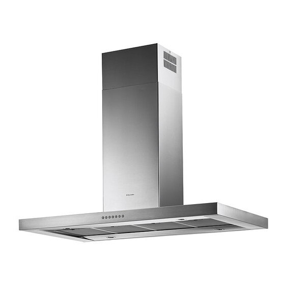
Inhaltszusammenfassung für Electrolux EFA 90540

  • Seite 1 EFA 90540 EFA 12540 Instructions Manual Manuel d’Instructions Bedienungsanleitung Gebruiksaanwijzing Kullanim Kilavuku...
  • Seite 2: Inhaltsverzeichnis

    Instructions Manual INDEX RECOMMENDATIONS AND SUGGESTIONS ........................7 CHARACTERISTICS................................8 INSTALLATION ..................................10 USE.......................................14 MAINTENANCE..................................16...
  • Seite 3 Manuel d’Instructions SOMMAIRE CONSEILS ET SUGGESTIONS ............................18 CARACTERISTIQUES .................................19 INSTALLATION ..................................21 UTILISATION..................................25 ENTRETIEN..................................27...
  • Seite 4 Bedienungsanleitung INHALTSVERZEICHNIS EMPFEHLUNGEN UND HINWEISE............................29 CHARAKTERISTIKEN................................30 MONTAGE....................................32 BEDIENUNG..................................36 WARTUNG....................................38...
  • Seite 5 Gebruiksaanwijzing INHOUDSOPGAVE ADVIEZEN EN SUGGESTIES .............................40 EIGENSCHAPPEN................................41 INSTALLATIE ..................................43 GEBRUIK....................................47 ONDERHOUD ..................................49...
  • Seite 6 Kullanim Kilavuku IÇERIKLER TAVSIYELER VE ÖNERILER ..............................51 ÖZELLIKLER ..................................52 MONTAJ ....................................54 KULLANIM ....................................58 BAKIM....................................60...
  • Seite 7: Recommendations And Suggestions

    RECOMMENDATIONS AND SUGGESTIONS The Instructions for Use apply to several versions of this appliance. Ac- cordingly, you may find descriptions of individual features that do not ap- ply to your specific appliance. INSTALLATION • The manufacturer will not be held liable for any damages resulting from incorrect or improper installation.
  • Seite 8: Characteristics

    CHARACTERISTICS Dimensions...
  • Seite 9 Components Ref. Q.ty Product Components Hood Body, complete with: Controls, Light, Blower, Filters Telescopic Chimney comprising: Upper Section 7.1a Lower Section Telescopic frame complete with extractor, consisting of: 7.1a Upper frame 7.1b Lower frame Reducer Flange ø 150-120 mm Flange ø 150 7.1b Dumper ø...
  • Seite 10: Installation

    INSTALLATION Drilling the Ceiling/shelf and fixing the frame DRILLING THE CEILING/SHELF • Use a plumb line to mark the centre of the hob on the ceiling/support shelf. • Place the drilling template 21 provided on the ceiling/support shelf, making sure that the template is in the correct position by lining up the axes of the template with those of the hob.
  • Seite 11 Fixing the frame • Loosen the two screws fastening the lower chimney and re- move this from the lower frame. • Loosen the two screws fastening the upper chimney and re- move this from the upper frame. If you wish to adjust the height of the frame, proceed as follows: •...
  • Seite 12 ø 150 Connections DUCTED VERSION AIR EXHAUST SYSTEM When installing the ducted version, connect the hood to the chimney using either a flexible or rigid pipe ø 150 or 120mm, the choice of which is left to the installer. To install a ø 150 •...
  • Seite 13: Electrical Connection

    Flue assembly - Mounting the hood body • Position the upper chimney section and fix the upper part to the frame using the 2 screws 12c (2,9 x 6,5) provided. • Similarly, position the lower chimney section and fix the lower part to the frame using the 2 screws 12c (2,9 x 6,5) pro- vided.
  • Seite 14: Use

    L T1 T2 T3 T4 T5 F The hood can be switched on pushing directly onto the requested speed without firstly hav- ing to select 0/1 button . Touch Basic functions Indicator lights control Dual Function Touch control unlit Lights off When briefly pressed it switches the lighting system on and off.
  • Seite 15: Basic Functions

    Touch Basic functions Indicator lights control When pressed the motor is set to the intensive speed timed to 5 minutes. At the end of 5 minutes of intensi- ve speed the hood starts again at the speed it was set Touch control lit to previously.
  • Seite 16: Maintenance

    MAINTENANCE REMOTE CONTROL (OPTIONAL) The appliance can be controlled using a remote control powered by a 1.5 V carbon-zinc alkaline batteries of the standard LR03- AAA type. • Do not place the remote control near to heat sources. • Used batteries must be disposed of in the proper manner. Grease filters CLEANING OF THE METAL CASSETTE FILTERS Alarm reset...
  • Seite 17: Light Replacement

    Odour filter (Recirculation Version) This filter cannot be washed or regenerated, and must be replaced when the F touch control starts to flash, or at least once every 4 months. The alarm is only triggered when the motor is on. Enabling/Disabling the alarm signal •...
  • Seite 18: Conseils Et Suggestions

    CONSEILS ET SUGGESTIONS La présente notice d'emploi vaut pour plusieurs versions de l'appareil. Elle peut contenir des descriptions d'accessoires ne figurant pas dans votre appa- reil. INSTALLATION • Le fabricant décline toute responsabilité en cas de dommage dû à une installa- tion non correcte ou non conforme aux règles de l’art.
  • Seite 19: Caracteristiques

    CARACTERISTIQUES Encombrement...
  • Seite 20 Composants Réf. Q.té Composants de Produit Corps Hotte équipé de: Comandes, Lumière, Filtres Cheminée Télescopique formée de : Cheminée Supérieure Cheminée Inférieure 7.1a Treillis télescopique avec Aspirateur, formé par: 7.1a Treillis supérieur 7.1b Treillis inférieur Flasque de Réduction ø 150-120 mm Flasque ø...
  • Seite 21: Installation

    INSTALLATION Perçage Plafond/Étagère et Fixation Treillis PERÇAGE PLAFOND/ETAGERE • À l’aide d’un Fil à plomb, reporter sur le Plafond/Étagère de support le centre du Plan de Cuisson. • Poser contre le Plafond/Étagère le Gabarit de Perçage 21 fourni avec l’appareil, en faisant coïncider son centre avec le centre projeté...
  • Seite 22 FiXATION TREILLIS • Dévisser les deux vis qui fixent la cheminée inférieure et sortir cette dernière du treillis (depuis la partie inférieure). • Dévisser les deux vis qui fixent la cheminée supérieure et sortir cette dernière du treillis (depuis la partie supérieure). Si l’on souhaite régler la hauteur du treillis, effectuer les opéra- tions suivantes: •...
  • Seite 23 ø 150 Branchements SORTIE AIR VERSION ASPIRANTE En cas d’installation en version aspirante, brancher la hotte à la tuyauterie de sortie via un tube rigide ou flexible de ø 150 ou 120 mm, au choix de l’installateur. Branchement avec un tube de ø150 •...
  • Seite 24: Branchement Electrique

    Montage Cheminée - Montage Corps Hotte • Positionner la Cheminée supérieure et fixer cette dernière dans la partie supérieure du Treillis à l’aide de 2 Vis 12c (2,9 x 6,5) fournies avec l’appareil. • De la même façon, positionner la Cheminée inférieure et fixer cette dernière dans la partie inférieure du Treillis à...
  • Seite 25: Utilisation

    UTILISATION L T1 T2 T3 T4 T5 F Il est possible d’allumer la hotte directement à la vitesse demandée en pressant la touche sans devoir d’abord utiliser la touche 0/1. Fonction base Touche Témoins lumineux Double fonction Appuyer brièvement sur cette touche pour allumer et Voyant éteint Lumières éteintes éteindre les lumières.
  • Seite 26 Touche Fonction base Témoins lumineux Fait fonctionner le moteur en vitesse intensive pendant 5 minutes. Après 5 minutes, l’appareil retourne à la vitesse choisie auparavant. Si la Voyant allumé mise en marche est effectuée quand l’appareil est éteint, après 5 minutes le système retourne à la première vitesse.
  • Seite 27: Entretien

    ENTRETIEN TELECOMMANDE (FOURNIE SUR DEMANDE) Il est possible de commander cet appareil au moyen d’une télé- commande, alimentée avec des piles alcalines zinc-charbon 1,5 V du type standard LR03-AAA. • Ne pas ranger la télécommande à proximité de sources de cha- leur.
  • Seite 28 Filtre anti-odeur (Version Filtrante) Il ne peut être ni lavé ni récupéré, il faut le changer quand la touche F clignote ou au moins tous les 4 mois. L’alarme fonctionne seulement quand le Moteur d’aspiration est en marche Activation/Désactivation du signal d’alarme •...
  • Seite 29: Empfehlungen Und Hinweise

    EMPFEHLUNGEN UND HINWEISE Diese Gebrauchsanleitung gilt für mehrere Geräte-Ausführungen. Es ist mög- lich, dass einzelne Ausstattungsmerkmale beschrieben sind, die nicht auf Ihr Gerät zutreffen. MONTAGE • Der Hersteller haftet nicht für Schäden, die auf eine fehlerhafte und unsach- gemäße Montage zurückzuführen sind. •...
  • Seite 30: Charakteristiken

    CHARAKTERISTIKEN Platzbedarf...
  • Seite 31 Komponenten Pos. Produktkomponenten Haubenkörper mit Schaltern, Teleskopkamin bestehend aus: oberer Kaminteil unterer Kaminteil 7.1a Teleskopgerüst komplett mit Gebläse, bestehend aus: 7.1a oberer Gerüstteil 7.1b unterer Gerüstteil Reduzierflansch ø 150-120 mm Flansch ø 150 Flansch mit Ruckstauklappe ø 150 7.1b Luftaustritt-Anschlussstück Verbindungsdose Rohrschellen Pos.
  • Seite 32: Montage

    MONTAGE Bohren der Decke/Trägerplatte und Montage des Teleskopgerüsts BOHREN DER DECKE/TRAGERPLATTE • Mit Hilfe eines Lots den Kochmulden-Mittelpunkt an der Decke oder Trägerplatte ermitteln und kennzeichnen. • Die mitgelieferte Bohrschablone 21 so auf die Decke/Trägerplatte legen, dass die Schablo- nenmitte mit dem gekennzeichneten Mittelpunkt übereinstimmt und die Schablonenseiten auf die Seiten der Kochmulde ausrichten.
  • Seite 33 Montage des Teleskopgerüsts • Die beiden Schrauben lösen, die den unteren Gerüstteil fixieren und diesen aus dem Gerüst ziehen (an der Unterseite) • Die beiden Schrauben lösen, die den oberen Gerüstteil fixieren und diesen aus dem Gerüst ziehen (an der Oberseite). Für eine eventuelle Regulierung der Gerüsthöhe folgendermaßen vorgehen: •...
  • Seite 34: Anschlüsse

    ø 150 Anschlüsse ANSCHLUSS IN ABLUFTVERSION Bei Abluftbetrieb kann die Haube vom Installateur wahlweise mittels Rohr oder Schlauch (ø150 oder 120mm) an die Außen- rohrleitung angeschlossen werden. Anschlussrohres ø 150 • Den Flansch mit Ruckstauklappe 10a anbringen. • Das Rohr mit geeigneten Rohrschellen fixieren.Das hierzu er- forderliche Material wird nicht mitgeliefert.
  • Seite 35: Elektroanschluss

    Kaminmontage und Montage des Haubenkörpers • Den oberen Kaminteil positionieren und beim oberen Gerüst- teil mit Hilfe der 2 mitgelieferten Schrauben 12c (2,9 x 6,5) fi- xieren. • Gleichermaßen den unteren Kaminteil positionieren und beim unteren Gerüstteil mit Hilfe der 2 mitgelieferten Schrauben 12c (2,9 x 6,5) fixieren.
  • Seite 36: Bedienung

    BEDIENUNG L T1 T2 T3 T4 T5 F Die Haube kann direkt auf die gewünschte Stufe eingeschaltet werden ohne daß man vorher auf die Gebläsetaste 0/1 drückt. Grundfunktion Taste Leuchtsignale Doppelfunktion Ein kurzer Tastendruck schaltet die Beleuchtungsanlage Taste erlo- Beleuchtung abgeschaltet ein und aus.
  • Seite 37 Taste Grundfunktion Leuchtsignale Aktiviert den Motor mit der 5 Minuten dauernden Intensiv- stufe. Nach Ablauf der 5 Minuten läuft das Gerät wieder mit der zuvor eingestellten Sauggeschwindigkeit. Wird Taste leuchtet auf diese Funktion bei abgeschaltetem Gerät aktiviert, wird nach Ablauf der 5 Minuten auf die erste Gebläsestufe übergegangen.
  • Seite 38: Wartung

    WARTUNG FERNBEDIENUNG (OPTION) Dieses Gerät kann mit einer Fernbedienung gesteuert werden, welche mit alkalischen Zink-Kohle-Batterien 1,5 V des Standard- typs LR03-AAA versorgt wird. • Die Fernbedienung nicht in die Nähe von Hitzequellen legen. • Batterien müssen vorschriftsmäßig entsorgt werden. Fettfilter REINIGUNG DER SELBSTTRAGENDEN METALLFETTFILTER Rückstellen der Sättigungsanzeige •...
  • Seite 39: Austauschen Des Aktivkohle-Geruchsfilter

    Geruchsfilter (Umluftbetrieb) Dieser Filter ist weder wasch- noch wiederverwendbar und ist auszutauschen, wenn die Taste F blinkt oder zumindest alle 4 Monate. Die Sättigungsanzeige erfolgt nur, wenn der Gebläse- motor eingeschaltet ist. Aktivierung/Deaktivierungder Sättigungsanzeige • Bei Hauben mit Umluftbetrieb erfolgt die Aktivierung der Sättigungsanzeige bei der Instal- lation oder später.
  • Seite 40: Adviezen En Suggesties

    ADVIEZEN EN SUGGESTIES Deze gebruiksaanwijzing geldt voor verschillende uitvoeringen van het appa- raat. Het is mogelijk dat er een aantal kenmerken worden beschreven die niet van toepassing zijn op uw apparaat. INSTALLATIE • De fabrikant aanvaardt geen enkele aansprakelijkheid voor schade die voort- komt uit onjuiste of niet overeenkomstig de regels der kunst uitgevoerde instal- laties.
  • Seite 41: Eigenschappen

    EIGENSCHAPPEN Buitenafmetingen...
  • Seite 42 Onderdelen Ref. Productonderdelen Wasemkap compleet met: Bedieningen, Licht, Filters Telescopische Schouw Bestaande uit: Bovenstuk Onderstuk 7.1a Telescopisch frame compleet met afzuiginrichting, bestaand uit: 7.1a Bovenste frame 7.1b Onderste frame Reductieflens ø 150-120 mm Flens ø 150 7.1b Toom met Klep ø 150 Verbindingsstuk Luchtuitlaat Aansluitdoos Leidingklemmen...
  • Seite 43: Installatie

    INSTALLATIE Gaten boren in plafond/plank en bevestiging frame GATEN BOREN IN PLAFOND/PLANK • Teken met behulp van een looddraad op het plafond/de draagplank het midden van de koo- kplaat af. • Houd de bijgeleverde boormal 21 tegen het plafond/de plank, en laat het midden hiervan samenvallen met het afgetekende punt en lijn de assen van de boormal uit met de assen van de kookplaat.
  • Seite 44 BEVESTIGING FRAME • Draai de twee schroeven los die het onderstuk vasthouden aan het frame en verwijder het (langst de onderkant) • Draai de twee schroeven los die het bovenstuk vasthouden aan het frame en verwijder het (langst de bovenkant) Als U de hoogte van het frame wil bijstellen, gaat als volgt te werk: •...
  • Seite 45 ø 150 Aansluitingen LUCHTUITLAAT AFZUIGVERSIE Bij installatie in afzuigversie, moet u de wasemkap met de uit- laatleiding verbinden door middel van een starre of buigzame leiding van ø 150 of 120 mm, naar keuze van de installateur. Leiding van ø150 •...
  • Seite 46: Elektrische Aansluiting

    Montage van de schouw - Montage van de Wasemkap • Breng het bovenste gedeelte van de schouw in positie en zet dit aan de bovenkant vast aan het frame met 2 van de bijgeleverde schroeven 12c (2,9 x 6,5). • Breng op dezelfde manier het onderste gedeelte van de schouw in positie en zet dit aan de onderkant vast aan het frame met 2 van de bijgeleverde schroeven 12c (2,9 x 6,5).
  • Seite 47: Gebruik

    GEBRUIK L T1 T2 T3 T4 T5 F De wasemkap kan rechtstreeks ingeschakeld worden op de gewenste snelheid, door de des- betreffende toets in te drukken zonder eerst de toets 0/1 motor te bedienen. Toets Basisfunctie Lichtsignalen Dubbele Functie Als U deze toets even indrukt, wordt de verlichting aan- Led uit Lichten uit of uitgeschakeld.
  • Seite 48 Toets Basisfunctie Lichtsignalen Activeert de zuigmotor gedurende 5 minuten in de intensieve snelheid. Na afloop van deze 5 minuten, schakelt het toestel over op de daar- voor ingestelde snelheid. Als U de wasemkap Led brandt meteen instelde in de intensieve snelheid, dan schakelt het systeem na 5 minuten over op de eerste snelheid.
  • Seite 49: Onderhoud

    ONDERHOUD AFSTANDSBEDIENING (OPTIE) Dit apparaat kan met behulp van een afstandsbediening worden bestuurd. Deze werkt op alkaline zinkkoolstof batterijen van 1,5 V van het standaardtype LR03-AAA. • Bewaar de afstandsbediening niet in de buurt van warmtebron- nen. • De batterijen mogen na gebruik niet in het milieu terechtko- men, gooi ze in de hiervoor bestemde afvalbakken.
  • Seite 50 Geurfilters met actieve koolstof (Filterversie) Deze filter is niet afwasbaar en kan niet herbruikt worden. De koolstoffilter moet vervangen worden als toets F knippert of minstens eenmaal in de 4 maanden. Het alarmsignaal wordt al- leen aangegeven als de zuigmotor actief is. Activering/Desactivering van het alarmsignaal •...
  • Seite 51: Tavsiyeler Ve Öneriler

    TAVSIYELER VE ÖNERILER Bu kullanma talimatι birden fazla cihaz modeli için geçerlidir. Cihazιnιza uymayan bazι donanιm özellikleri tarif edilmiş olabilir. MONTAJ • Yalnιş veya eksik montajdan doğan herhangi bir zararιn sorumluluğu üreticiye ait değildir. • Davlumbaz ile pişirici cihazιn ocak kιsmι arasιndaki minimum güvenlik mesafesi 650 mm.dir.
  • Seite 52: Özellikler

    ÖZELLIKLER Boyutlar...
  • Seite 53 Parçalar Ref. Adet Ürün Parçaları Şunlardan oluşan Davlumbaz Gövdesi: Kumandalar, Lamba, Filtreler Şunlardan oluşan Teleskopik Baca: Üst Baca 7.1a Alt Baca Şunlardan oluşan Aspiratörlü teleskopik kafes: 7.1a Üst kafes 7.1b Alt kafes Redüksiyon Flanşı ø 150-120 mm Flanş ø 150 7.1b Valfli flanş...
  • Seite 54: Montaj

    MONTAJ Tavan / Konsol delme işlemi ve Kafesin Sabitlenmesi TAVANIN YADA KONSOLUN DELİNMESİ • Bir şakül yardımıyla tavana ya da destek konsolüne pişirme tezgahının merkezini işaretleyi- niz. • Tavana veya konsola donanımla birlikte verilen delik delme şablonunu (21) dayayınız ve bunun merkeziyle işaretlenen merkezi birbirine çakıştırınız.
  • Seite 55 Kafesin Sabitlenmesi • Alt bacayı sabitleyen iki adet vidayı söküp kafesten çıkarınız (alt kısımdan). • Üst bacayı sabitleyen iki adet vidayı söküp kafesten çıkarınız (üst kısımdan). Kafesin yüksekliği ayarlanmak istenirse, şu şekilde hareket edil- melidir: • Kafesin iki yanında bulunan sütunları birleştiren sekiz adet metrik vidayı...
  • Seite 56 ø 150 Anschlüsse ANSCHLUSS IN ABLUFTVERSION Bei Abluftbetrieb kann die Haube vom Installateur wahlweise mittels Rohr oder Schlauch (ø150 oder 120mm) an die Außen- rohrleitung angeschlossen werden. Anschlussrohres ø 150 • Den Flansch mit Ruckstauklappe 10a anbringen. • Das Rohr mit geeigneten Rohrschellen fixieren.Das hierzu er- forderliche Material wird nicht mitgeliefert.
  • Seite 57: Elektri̇k Bağlantisi

    Baca Montajı ve Davlumbaz Gövdesinin Sabitlenmesi • Üst Bacayı yerleştiriniz ve cihaz donanımındaki 2 adet vidayı 12c (2,9 x 6,5) kullanarak yukarı kısımdan Kafese sabitleyiniz. • Aynı şekilde alt Bacayı da yerleştiriniz ve cihaz donanımındaki 2 adet vidayı 12c (2,9 x 6,5) kullanarak aşağı kısımdan Kafese sabitleyiniz.
  • Seite 58: Kullanim

    KULLANIM L T1 T2 T3 T4 T5 F 0/1 motor tuşu ile birlikte ilgili tuşa basarak davlumbaz istediğiniz hızda çalıştırılabilmekte- dir. Tuş Temel fonksiyon Işıklı işaretler Çift Fonksiyon Kısa bir süre basılı tutulmak suretiyle aydınlatma terti- Tuş sönük Işıklar sönük batını...
  • Seite 59 Tuş Temel fonksiyon Işıklı işaretler Motoru 5 dakikaya ayarlanmış yoğun hızda aktive etmek- tedir. 5 dakikanın sonunda cihaz bir önceki ayarlanmış hıza dönmektedir. 5 dakikalık sürenin sonunda sönmüş Tuş ışığı açık olan cihazın tekrardan çalıştırılması halinde sistem ilk hızına geri dönmektedir. 4 saniye süreyle basılı...
  • Seite 60: Bakim

    BAKIM TELEKUMANDA (OPSİYONEL) Bu cihaza bir telekumanda ile de komut verilebilir; bu kumanda 1,5 Voltluk çinko-karbonlu LR03-AAA tipi standart alkalin pil- lerle çalışır. • Telekumandayı ısı kaynakları yakınında bırakmaynız. • Pilleri çevreye atmayınız, bunlara ayrılmış çöp toplama kapla- rına atınız. Yağlanmaya karşı...
  • Seite 61: Filtrenin Değiştirilmesi

    Koku Emici Filtre (Filtre edici Versiyon) Yıkanamaz, geri dönüşümlü değildir, ekranda F sembolü görüntülendiğinde veya en az 4 ayda bir değiştirilir. Alarm sinyali sadece Aspirasyon Motoru çalıştırıldığı zaman gerçekleşmekte- dir. Alarm sinyalinin devreye sokulması /devreden çıkartılması • Filtre edici versiyon Davlumbazlarda, Filtreler doygunluk Alarm sinyali, kurulum anında veya devamında aktive olur.
  • Seite 64 The symbol on the product or on its packaging indicates that this product may not be treated as household waste. Instead it shall be handed over to the applicable collection point for the recycling of electrical and electronic equipment. By ensuring this product is disposed of correctly, you will help prevent potential negative consequences for the environment and human health, which could oth- erwise be caused by inappropriate waste handling of this product.

Diese Anleitung auch für:

Efa 12540Efa90540xEfa12540x

Inhaltsverzeichnis