Werbung
Quicklinks
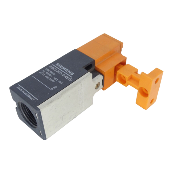
Sicherheitspositionsschalter
gekapselt mit getrenntem Betßtiger
Position switch (in safety circuits),
fully enclosed with separate actuator
Betriebsanleitung
Der Positionsschalter wird als Geradeaus> und als Radiusbetßtiger eingesetzt.
Montage
Ma˚bilder siehe Bild ¡ (Ma˚e in mm)
Zum Schutz vor eberfahren darf dieses Ma˚ nicht unterschritten werden.
1)
2)
Mittenversatz
zwischen
Schalter
vertikal!±1!mm.
a Getrennter Betßtiger, seitliche Betßtigung 3SE3200>0XB, >0XE
b Getrennter Betßtiger, axiale, stirnseitige Betßtigung 3SE3200>0XD, >0XF
K=Kurzer Betßtiger, L=Langer Betßtiger
Befestigung auf planer Flßche mit 2 Schrauben M4.
Stets Scheiben und Federringe beilegen.
Einbaulage beliebig.
Hinweis: Bei der Montage ist ein Befestigungsabstand von 20 mm zu
wßhlen oder der Schalter zu verstiften.
Anschlu˚
Bei Verwendung von metallischen PG>Verschraubungen wird die Schutz>
ma˚nahme Schutzisolierung durchbrochen. Die Metallverschraubung ist in
eine andere Schutzma˚nahme einzubeziehen.
Maximale Anschlu˚querschnitte (Schraubanschlu˚):
eindrßhtig
feindrßhtig mit AderendhÂlse
Anschlu˚schrauben
Anziehdrehmoment
Die KabelfÂhrung (Pg 13,5) ist sorgfßltig abzudichten, um die Verminderung
der Schutzart zu vermeiden.
Betrieb
Betßtiger, siehe Bild ¬.
K
Kurzer Betßtiger
L
V max.
maximale Betßtigungsgeschwindigkeit
F min.
Mindestkraft in Betßtigungsrichtung
Der Positionsschalter kann nur mit dem dazugeh'rigen dreifach codierten
Betßtiger geschaltet werden. eberlisten auf einfache Weise von Hand oder
mit einem Hilfsmittel ist ausgeschlossen. Durch Ziehen des Betßtigers wird
der Tffner zwangslßufig ge'ffnet und der Schlie˚er geschlossen.
Hinweis: Der Antrieb ist bei 3SE3200>0XB, >0XE um 4¥90∞ versetzbar.
Instructions
The position switch can be used as direct and radius actuator.
Mounting
For dimension drawings see Fig. I (dimensions in mm)
1)
For protection against overriding, this dimension must not be less than
indicated.
2)
Centre offset between switch and actuator: horizontal and vertical 1mm.
a Separate actuator: side actuation 3SE3200>0XB, >0XE
b Separate actuator: axial/front actuation 3SE3200>0XD, >0XF
K=short actuator, L=long actuator
Mount on a flat surface using two M4 screws.
Always fit flat washers and spring washers.
Mounting position: as desired.
Note: For mounting a fixing distance of 20 mm should be selected or the
switch located by pins.
Connection
When using metallic Pg glands, the ∫total insulation∫ requirement is no
longer met. Another protective measure should be selected.
Max. conductor cross>sections (screwed connection):
Solid
Finely stranded with end sleeve
Terminal screws
Tightening torque
Carefully seal the cable entry (Pg 13.5) to retain the degree of protection
stated.
Operation
Actuator see Fig. II
K
short actuator
L
V max.
Max. actuating speed
F min.
Min. force required in actuating direction
The position switch can only be operated with the associated actuator
(coded three times). Simple bypassing by hand or another means is excluded.
By pulling the actuator, the break contact can be opened and the make
contact closed.
Note: The operating mechanism can be repositioned through 4¥90∞
GWA 4NEB 330 0031>10a
und
Betßtiger
horizontal
2
2¥ 2,5 mm
2
2¥ 1,5 mm
M3,5
0,8 ... 1,2 Nm
Langer Betßtiger
2
2¥ 2.5 mm
2
2¥ 1.5 mm
M3.5
0.8 to 1.2 Nm
long actuator
,
Bestell>Nr.: 3ZX1012>0SE32>0AA1
Positionsschalter nicht als Anschlag verwenden!
Schaltelement: Schaltglieder mit einem zwangslßufigen Tffner und
einem zwangslßufig 'ffnenden Schlie˚er.
Gerßteschaltplan: Anschlu˚bezeichnungen nach EN 50013
Nennschaltweg und zugeh'rige Anschlu˚klemmen siehe Bild √
und
Schaltglied geschlossen
Betßtigungsrichtung
Instandhaltung
Positionsschalter sind wartungsfrei.
Technische Daten
Schutzart
Zulßssige Umgebungstemperatur
Thermischer Bemessungsstrom I
Bemessungsbetriebsspannung U
(40 bis 60 Hz)
Âber AC 380 V nur gleiches Potential
24 V
125 V
230/220 V
400/380 V
500 V
Bemesssungsbetriebsspannung U
(Gleichstrom)
24 V
48 V
110 V
220 V
440 V
Kurzschlu˚schutz gemß˚
> DIAZED>Sicherungseinsßtze
> Schutzautomat (G>Charakteristik)
Order No. 3ZX1012>0SE32>0AA1
(3SE3200>0XB, >0XE only). Do not use the position switch as a stop!
Contact block:
Elements with one positive break contact and one
make contact with positive opening action.
Wiring diagram: Terminal designations to EN 50013
Nominal contact travel and associated terminals see Fig. III
Contact closed
Direction of actuation
Maintenance
Position switches require no maintenance.
Technical data
Degree of protection
Permissible ambient temperature
Rated thermal current I
Rated operating voltage U
(AC, 40 to 60 Hz)
above 380 V AC equal potential only
24 V
125 V
230/220 V
400/380 V
500 V
Rated operating voltage U
(DC)
24 V
48 V
110 V
220 V
440 V
Short circuit protection
> DIAZED fuse links
> MCB (G characteristic)
3SE3 200
U
500 V AC, U
i
DIN VDE 0660, IEC 60947>5>1
Schaltglied ge'ffnet
IP 65
> 30 ...+85 ∞C
10 A
th
e
I
/AC>12
e
10 A
10 A
10 A
10 A
10 A
e
I
/DC>12
e
10 A
6 A
4 A
1 A
0,5 A
DIN VDE 0660 Teil 200
10A Dz
6 A TDz
10 A
Contact opened
IP 65
> 30 to+85 ∞C
10 A
th
e
I
/AC>12
e
10 A
10 A
10 A
10 A
10 A
e
I
/DC>12
e
10 A
6 A
4 A
1 A
0.5 A
to DIN VDE 0660 Part 200
10A Dz
6 A TDz
10 A
600 V DC
i
I
/AC>15
e
10 A
10 A
6 A
4 A
3 A
I
/DC>13
e
10 A
4 A
1 A
0,4 A
0,2 A
I
/AC>15
e
10 A
10 A
6 A
4 A
3 A
I
/DC>13
e
10 A
4 A
1 A
0.4 A
0.2 A
1
Werbung

Verwandte Anleitungen für Siemens 3SE3 200


Inhaltszusammenfassung für Siemens 3SE3 200
- Seite 1 Sicherheitspositionsschalter 3SE3 200 gekapselt mit getrenntem Betßtiger 500 V AC, U 600 V DC Position switch (in safety circuits), fully enclosed with separate actuator DIN VDE 0660, IEC 60947>5>1 Betriebsanleitung Bestell>Nr.: 3ZX1012>0SE32>0AA1 Positionsschalter nicht als Anschlag verwenden! Der Positionsschalter wird als Geradeaus> und als Radiusbetßtiger eingesetzt.