Werbung
Quicklinks
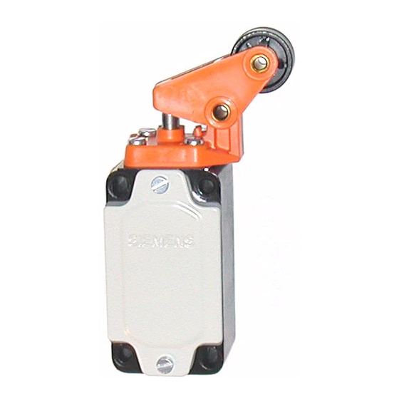
Sicherheitspositionsschalter
mit getrenntem Betätiger
Safety Position Switch,
with seperate actuator
Betriebsanleitung
Montage
Maßbilder siehe Bild I (Maße in mm)
Befestigung auf planer Fläche mit 4 Schrauben M5.
Stets Scheiben und Federringe beilegen.
Einbaulage beliebig.
Anschluss
Die Anschlussschrauben (SIGUT-Anschlusstechnik) ermöglichen die Verwendung
von Motorschraubern.
Maximale Anschlussquerschnitte:
eindrähtig
feindrähtig mit Aderendhülse
Anschlussschrauben
Schutzleiteranschluss im Gehäuse
Anziehdrehmoment
Die Kabelführung (Pg 13,5) ist sorgfältig abzudichten, um die Verminderung der
Schutzart zu vermeiden.
Betrieb
Antrieb, siehe Bild II
V
Maximale Betätigungsgeschwindigkeit
max.
F
Mindestkraft in Betätigungsrichtung
min.
Der Positionsschalter kann nur mit dem dazugehörigen dreifach codierten Betätiger
geschaltet werden. Überlisten auf einfache Weise von Hand oder mit einem Hilfs-
mittel ist ausgeschlossen.
Durch Ziehen des Betätigers wird der Öffner zwangsläufig geöffnet und
der Schließer geschlossen.
Hinweis: Der Antrieb ist um 4×90° versetzbar. Positionsschalter nicht als
Anschlag verwenden!
Schaltelement: Schaltglieder mit einem zwangsläufigen Öffner und einem
Schließer.
(Anschlussbezeichnungen nach EN 50013)
Operating Instructions
Installation
For dimension drawings see Fig. I (dimensions in mm)
Mounting on level surface with 4 M5 screws.
Always fit plain and spring washers.
Any position of mounting permissible.
Connection
The screws of the SIGUT termination system allow the use of power screwdrivers.
Maximum conductor sizes:
Solid
Finely stranded with core end sleeve
Terminal screws
Earthing connection in housing
Tightening torque
The cable entry (Pg 13.5) must be carefully sealed to retain the degree of protection
stated.
Operation
Operating mechanism see Fig. II
V
Maximum actuation speed
max.
F
Minimum force in direction of actuation
min.
The position switch can be operated only with the relevant triplecoded actuator.
Overriding by hand or with tool is not possible.
Pulling the actuator forces the NC contact open and the NO contact closed.
Note: The actuator can be repositioned every 90° (4×). The position switch may not
be used as a mechanical stop!
Contact arrangement: One positive NC contact and one NO contact.
(Terminal markings to EN 50013)
GWA 4NEB 330 0893-10b
, metallgekapselt
metal-enclosed
2
2×2,5 mm
2
2×1,5 mm
M3,5
M3,5
0,8 bis 1,2 Nm
2
2× 2.5 mm
2
2× 1.5 mm
M3.5
M3.5
0.8 to 1.2 Nm
Bestell-Nr.: 3ZX1012-0SE31-0AA1
Nennschaltung und zugehörige Anschlussklemmen siehe Bild III
Schaltglied geschlossen
Betätigungsrichtung
Instandhaltung
Positionsschalter sind wartungsfrei.
Technische Daten
Schutzart
Zulässige Umgebungstemperatur
Bemessungsisolationsspannung
Bemessungsbetriebsstrom I
/AC-12
e
Bemessungsbetriebsspannung U
e
24 V
125 V
230/220 V
400/380 V
500 V
Bemessungsbetriebsspannung U
e
24 V
48 V
110 V
220 V
440 V
Kurzschlussschutz (gemäß DIN VDE 0660 Teil 200)
- DIAZED-Sicherungseinsätze
- Schutzautomat (G-Charakteristik)
Order No.: 3ZX1012-0SE31-0AA1
For nominal circuit and relevant terminals see Fig. III
Contact closed
Direction of actuation
Maintenance
Position switches are maintenance-free.
Technical data
Degree of protection
Permissible ambient temperature
Insulation rating
Rated operational current I
/AC-12
e
Rated operating voltage U
e
24 V
125 V
230/220 V
400/380 V
500 V
Rated operating voltage U
e
24 V
48 V
110 V
220 V
440 V
Short-circuit protection (to DIN VDE 0660 Part 200)
- DIAZED fuse links
- Miniature circuit-breaker
(G-characteristic)
3SE3 120
DIN VDE 0660, IEC 60947
Deutsch
Schaltglied geöffnet
IP67
–40 bis +85 °C
AC 500 V; DC 600 V
10 A
Bemessungsbetriebsstrom I
/AC -15
e
10 A
10 A
6 A
4 A
3 A
Bemessungsbetriebsstrom I
e
DC-12
DC-13
10 A
10 A
6 A
4 A
4 A
1 A
1 A
0,4 A
0,5 A
0,2 A
10A Dz
6 A TDz
10 A
English
Contact opened
IP67
–40 to +85 °C
AC 500 V; DC 600 V
10 A
Rated operational current I
/AC -15
e
10 A
10 A
6 A
4 A
3 A
Rated operational current I
e
DC-12
DC-13
10 A
10 A
6 A
4 A
4 A
1 A
1 A
0.4 A
0.5 A
0.2 A
10 A Dz
6 A TDz
10 A
1
Werbung

Inhaltszusammenfassung für Siemens 3SE3 120
- Seite 1 Sicherheitspositionsschalter 3SE3 120 , metallgekapselt mit getrenntem Betätiger Safety Position Switch, metal-enclosed DIN VDE 0660, IEC 60947 with seperate actuator Deutsch Betriebsanleitung Bestell-Nr.: 3ZX1012-0SE31-0AA1 Montage Nennschaltung und zugehörige Anschlussklemmen siehe Bild III Schaltglied geschlossen Schaltglied geöffnet Maßbilder siehe Bild I (Maße in mm) Betätigungsrichtung...
- Seite 2 Interrupteur de position de sécurité 3SE3 120 sous boîtier avec came d’attaque séparée Interruptor de posición de seguridad , blindado DIN VDE 0660, IEC 60947 con actuador separado Français Instructions de service N° de réf. : 3ZX1012-0SE31-0AA1 Montage Diagramme de fonctionnement des contacts, cf. fig. III contact fermé...
- Seite 3 Pulsanti finecorsa di sicurezza 3SE3 120 , in cassetta di metallo con attuatore separato Lättmetallkapslade gränslägesbrytare DIN VDE 0660, IEC 60947 med separat manöverdon Italiano Istruzioni di servizio No. d'ordinaz.: 3ZX1012-0SE31-0AA1 Montaggio Per la commutazione nominale e relativi morsetti di collegamento ved. fig. III...
- Seite 4 Telephone: +49 (0) 180 50 50 222 Technische Änderungen vorbehalten Zum späteren Gebrauch aufbewahren! Bestell-Nr./Order No.: 3ZX1012-0SE31-0AA1 Subject to change without prior notice. Store for use at a later date. Printed in the Federal Republic of Germany © Siemens AG 1992...


