Herunterladen Inhalt Inhalt Diese Seite drucken
Epson ELPMB29 Bedienungsanleitung
Vorschau ausblenden Andere Handbücher für ELPMB29:

Werbung

Verfügbare Sprachen
  • DE

Verfügbare Sprachen

  • DEUTSCH, seite 26
User's Guide ........................ 2
Manuale dell'utente ......... 37
Manual de usuario............ 49
使用说明书 ........................ 73
使用說明書 ........................ 85
取扱説明書 ........................ 97
Printed in China
XX.XX-.XX(XXX)

Werbung

Inhaltsverzeichnis
loading

Inhaltszusammenfassung für Epson ELPMB29

  • Seite 1: Inhaltsverzeichnis

    User's Guide ......2 Guide de l'utilisateur..13 Bedienungsanleitung ..25 Manuale dell'utente ..37 Manual de usuario.... 49 Manual do Utilizador ..61 使用说明书 ......73 使用說明書 ......85 取扱説明書 ......97 Printed in China XX.XX-.XX(XXX)
  • Seite 2: Safety Instructions

    Safety Instructions For your safety, read all the instructions in this guide, the User's Guide for your projector, and Safety Instructions before using this product. Incorrect handling that ignores instructions in these guides could damage the product or could result in personal injury or property damage. Keep this guide at hand for future reference.
  • Seite 3: About This Guide

    Such an environment may damage the projector. About This Guide This guide describes how to install the following projectors to a table using the Interactive Table Mount (ELPMB29). EB-485Wi/EB-485W/EB-480i/EB-480/EB-475Wi/EB-475W/EB-470 BrightLink 485Wi/BrightLink 485Wi+/BrightLink 480i/BrightLink 475Wi/BrightLink 475Wi+ 1. Package Contents Base frame unit with adjuster bolts...
  • Seite 4 2. Specifications Item Specification Remark Mass Approx. 7.5 kg Maximum load capacity 6.5 kg Forward/backward adjustment 80 mm (3.1") Distance between the edge of the table and the center of range of the adjuster bolt the bolt: 35 to 115 mm (1.4 to 4.5") 3.
  • Seite 5  If any obstacles such as a shaft exist on the bottom side of the tabletop, the distance between the edge of the table and the obstacle must be at least 75 mm (3") or the obstacle must be within 85 mm (3.3") from the edge of the table.
  • Seite 6: Installation Procedure

    4. Installation Procedure Determine the image size and the position of the projector (1) Determine the position according to the image size. There are two positions ( the following illustration) to choose from. See the following table for the position suitable for each image size. EB-485Wi/485W/475Wi/475W BrightLink 485Wi/BrightLink 485Wi+/BrightLink 475Wi/BrightLink 475Wi+ [Unit: inch (mm)]...
  • Seite 7 EB-480i/480/470 BrightLink 480i [Unit: inch (mm)] Projection Image Size (S) Distance Between Distance Between Distance the Edge of the the Edge of the Aspect ratio Aspect ratio 4:3 Aspect ratio 16:9 Table and the Table and the Top 16:10 Bottom of the of the Screen Screen (4:3)(a) (4:3)(b)
  • Seite 8 Assemble the parts (1) Mount the attachment plate on the projector using M4 x 12 mm hexagon socket head cap bolts (4 bolts with washer and spring washer). Attachment plate M4 x 12 mm hexagon socket head cap bolts (with washer and spring washer) (2) Mount the tray on the base frame unit using an M4 x 8 mm hexagon socket head cap bolt.
  • Seite 9 Determine the position to attach the table mount (1) Loosen the adjuster bolts (x3) to fit the thickness of the tabletop, so that you can attach the base frame unit to the tabletop. Adjuster bolts (2) Attach the base frame unit to the table by sliding the base frame unit onto the edge of the table.
  • Seite 10 (3) Align one side of the U-shaped arch on the base frame unit ( in the following illustration) and the supposed central line of the screen during projection ( in the following illustration) to align the center of the lens and the center of the screen. U-shaped arch Center of the screen Table...
  • Seite 11 Warning ❏ Tighten all adjuster bolts firmly after installation. Otherwise, this product or the projector may fall or collapse, and cause personal injury or an accident. ❏ Do not attempt to tighten adjuster bolts on obstacles. Secure the projector to the base frame unit (1) Slide the attachment plate mounted on the projector onto the U-shaped arch from the top.
  • Seite 12: Tighten The Adjuster Bolts Fixed Temporarily In Step

    (2) Secure the projector with M8 x 35 mm hexagon socket head cap bolts (x2). M8 x 35 mm hexagon socket head cap bolts Tighten the adjuster bolts fixed temporarily in step Tighten the three adjuster bolts with equal force. Warning Tighten all screws firmly.
  • Seite 13: Guide De L'utilisateur

    Interactive Table Mount Guide de l'utilisateur Français...
  • Seite 14: Explication Des Symboles

    Consignes de sécurité Pour votre sécurité, veuillez lire toutes les consignes contenues dans ce guide, le Guide de l'utilisateur de votre projecteur, ainsi que les Consignes de sécurité avant d’utiliser ce produit. Une manipulation incorrecte ne respectant pas ces consignes pourrait endommager le produit ou provoquer des blessures corporelles ou des dommages matériels.
  • Seite 15: À Propos De Ce Guide

    Un tel environnement peut endommager le projecteur. À propos de ce Guide Ce guide décrit comment installer les projecteurs suivants sur une table à l'aide de Interactive Table Mount (ELPMB29). EB-485Wi/EB-485W/EB-480i/EB-480/EB-475Wi/EB-475W/EB-470 BrightLink 485Wi/BrightLink 485Wi+/BrightLink 480i/BrightLink 475Wi/BrightLink 475Wi+ 1. Contenu de l’emballage Châssis avec boulons de réglage...
  • Seite 16 Boulons Forme Quantité Application Boulon à tête cylindrique à 6 pans M8 x 35 mm Pour le montage de la plaque de fixation au châssis. Préparez les outils nécessaires avant de commencer l’installation. 2. Spécifications Élément Spécification Remarque Poids Environ 7,5 kg Capacité...
  • Seite 17  En présence d’obstacles (une poutre par exemple) au bas du plateau, la distance entre le bord de la table et l’obstacle doit être de 75 mm (3 pouces) minimum ou l’obstacle doit se trouver à 85 mm (3,3 pouces) du bord de la table.
  • Seite 18: Procédure D'installation

    4. Procédure d’installation Déterminer la taille d’image et la position du projecteur (1) Déterminez la position en fonction de la taille d’image. Deux positions ( dans l’illustration suivantes) sont possibles. Reportez-vous au tableau suivant pour déterminer la position adaptée à chaque taille d’image. EB-485Wi/485W/475Wi/475W BrightLink 485Wi/BrightLink 485Wi+/BrightLink 475Wi/BrightLink 475Wi+ [Unité...
  • Seite 19 EB-480i/480/470 BrightLink 480i [Unité : pouces (mm)] Distance Taille d’image (S) Distance entre le Distance entre le bord de la table et bord de la table et Rapport largeur/ Rapport largeur/ Rapport largeur/ projection le bas de l’écran le haut de l’écran hauteur 16:10 hauteur 4:3 hauteur 16:9...
  • Seite 20 Assembler les pièces (1) Installez la plaque de fixation au projecteur à l’aide des boulons à tête cylindrique à six pans M4 x 12 mm (4 boulons avec rondelle et rondelle élastique). Plaque de fixation Boulons à tête cylindrique à six pans M4 x 12 mm (avec rondelle et rondelle élastique) (2) Installez le plateau sur le châssis à...
  • Seite 21 Déterminer la position de fixation de la base de la table (1) Desserrez les boulons de réglage (x3) en fonction de l’épaisseur du plateau afin de pouvoir fixer le châssis au plateau. Boulons de réglage (2) Fixez le châssis à la table en faisant coulisser le châssis sur le bord de la table. Châssis...
  • Seite 22 (3) Alignez un côté de l'arc en forme de U avec le châssis ( dans l’illustration suivante) et la ligne centrale supposée de l’écran pendant la projection ( dans l’illustration suivante) afin d’aligner le centre de l’objectif avec le centre de l’écran. Arc en forme de U Centre de l’écran Table...
  • Seite 23 Avertissement ❏ Serrez fermement tous les boulons de réglage après l’installation. Sinon, le produit ou le projecteur peut tomber ou s’affaisser et provoquer des blessures corporelles ou un accident. ❏ Ne tentez pas de serrer les boulons de réglage sur des obstacles. Fixer le projecteur au châssis (1) Faites coulisser la plaque de fixation installée sur le projecteur sur l’arc en forme de U situé...
  • Seite 24 (2) Fixez le projecteur à l’aide des boulons à tête cylindrique à six pans M8 x 35 mm (x2). Boulons à tête cylindrique à 6 pans M8 x 35 mm Serrez les boulons de réglage fixés temporairement à l’étape Serrez les trois boulons de réglage de manière uniforme. Avertissement Serrez fermement toutes les vis.
  • Seite 25: Bedienungsanleitung

    Interactive Table Mount Bedienungsanleitung Deutsch...
  • Seite 26: Sicherheitsanweisungen

    Sicherheitsanweisungen Lesen Sie zu Ihrer Sicherheit vor der Verwendung dieses Produkts alle Anweisungen in dieser Anleitung, der Bedienungsanleitung für Ihren Projektor und die Sicherheitsanweisungen. Unsachgemäße Handhabung aufgrund Nichtbeachtung der Anweisungen in diesen Anleitungen könnte zu einer Beschädigung des Produkts oder zu Verletzungen oder Sachschäden führen. Halten Sie diese Anleitung stets griffbereit, um ggf. später darauf zurückgreifen zu können.
  • Seite 27: Über Diese Anleitung

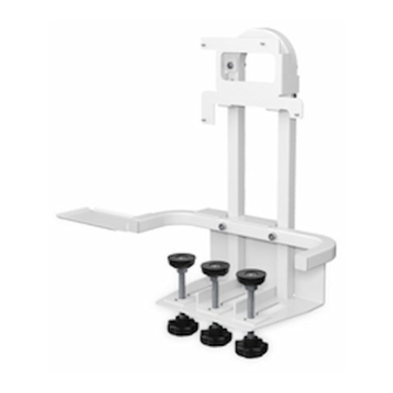
    Bringen Sie dieses Produkt nicht an einem Ort an, an dem die Betriebstemperatur des Projektors überstiegen wird. Dies könnte zu Beschädigungen am Projektor führen. Über diese Anleitung Diese Anleitung erläutert die Installation der folgenden Projektoren an einem Tisch mithilfe des Interactive Table Mount (ELPMB29). EB-485Wi/EB-485W/EB-480i/EB-480/EB-475Wi/EB-475W/EB-470 1. Verpackungsinhalt Basisgestell mit Einstellschrauben Montageplatte Fach Sechskantschlüssel (für M4 und...
  • Seite 28: Technische Daten

    Schrauben Form Name Anzahl Verwendung 35 mm lange M8-Innensechskantschraube Zum Anbringen der Montageplatte am Basisgestell Halten Sie alle notwendigen Werkzeuge griffbereit, bevor Sie mit der Installation beginnen. 2. Technische Daten Punkt Technische Daten Anmerkung Gewicht Ca. 7,5 kg Maximale Tragfähigkeit 6,5 kg Vorwärts-/Rückwärts- 80 mm (3,1")
  • Seite 29  Wenn sich Hindernisse wie Wellen usw. an der Unterseite der Tischplatte befinden, muss der Abstand zwischen der Tischkante und dem Hindernis mindestens 75 mm (3") betragen oder das Hindernis muss sich innerhalb von 85 mm (3,3") von der Tischkante befinden. 15 bis 80 mm (0,6 bis 3,1") 75 mm oder mehr...
  • Seite 30: Bestimmen Der Bildgröße Und Der Position Des Projektors

    4. Installation Bestimmen der Bildgröße und der Position des Projektors (1) Bestimmen Sie die Position entsprechend der Bildgröße. Sie können zwischen zwei Position in der nachfolgenden Abbildung) wählen. Siehe folgende Tabelle für die geeignete Position für jede Bildgröße. EB-485Wi/485W/475Wi/475W [Einheit: Zoll (mm)] Projektions- Bildgröße (S) Abstand zwischen der...
  • Seite 31 EB-480i/480/470 [Einheit: Zoll (mm)] Projektions- Bildgröße (S) Abstand zwischen der Abstand zwischen der abstand (Y) Tischkante und der Tischkante und der Bildformat 16:10 Bildformat 4:3 Bildformat 16:9 unteren Kante der oberen Kante der Projektionsfläche Projektionsfläche (4:3)(a) (4:3)(b) Fern Fern Fern Fern Fern 15,0...
  • Seite 32: Montieren Der Teile

    Montieren der Teile (1) Montieren Sie die Montageplatte mithilfe der 12 mm langen M4-Innensechskantschrauben (4 Schrauben mit Unterlegscheibe und Federscheibe) am Projektor. Montageplatte 12 mm lange M4- Innensechskantschraube (mit Unterlegscheibe und Federscheibe) (2) Montieren Sie das Fach mithilfe einer 8 mm langen M4-Innensechskantschraube am Basisgestell.
  • Seite 33 Bestimmen der Position zum Anbringen der Tischbefestigung (1) Lösen Sie die Einstellschrauben (3x) entsprechend der Dicke der Tischplatte, damit Sie das Basisgestell an der Tischplatte anbringen können. Einstellschrauben (2) Befestigen Sie das Basisgestell am Tisch, indem Sie es auf die Tischplatte schieben. Basisgestell...
  • Seite 34: Befestigen Des Basisgestells Durch Anziehen Der Einstellschrauben

    (3) Richten Sie eine Seite des U-förmigen Bogens des Basisgestells ( in der folgenden Abbildung) und die angenommene Mittellinie der Projektionsfläche während des Projizierens ( in der folgenden Abbildung) an der Mitte des Objektivs und der Mitte der Projektionsfläche aus. U-förmiger Bogen Mitte der Projektionsfläche Tisch...
  • Seite 35 Warnung ❏ Ziehen Sie alle Einstellschrauben nach der Installation fest an. Anderenfalls kann dieses Produkt oder der Projektor herunterfallen und kollabieren und einen Unfall verursachen oder Personen verletzen. ❏ Versuchen Sie nicht, die Einstellschrauben auf einem Hindernis fest zu ziehen. Sicheres Befestigen des Projektors an der Einstelleinheit (1) Schieben Sie die am Projektor angebrachte Montageplatte von oben auf den U-förmigen Bogen.
  • Seite 36: Anziehen Der Vorübergehend In Schritt Einstellschrauben

    (2) Sichern Sie den Projektor mit 35 mm langen M8-Innensechskantschrauben (2x). 35 mm lange M8- Innensechskantschrauben Anziehen der vorübergehend in Schritt angezogenen Einstellschrauben Ziehen Sie die drei Einstellschrauben mit gleicher Kraft fest. Warnung Ziehen Sie alle Schrauben fest an. Anderenfalls kann der Projektor oder dieses Produkt herunterfallen und einen Unfall verursachen oder Personen verletzen.
  • Seite 37: Manuale Dell'utente

    Interactive Table Mount Manuale dell'utente Italiano...
  • Seite 38: Istruzioni Sulla Sicurezza

    Istruzioni sulla sicurezza Per motivi di sicurezza, leggere tutte le istruzioni del presente manuale, il Manuale dell'utente del proiettore e le Istruzioni sulla sicurezza prima di utilizzare il prodotto. Una manipolazione scorretta, che ignora le istruzioni dei suddetti manuali, può danneggiare il prodotto e causare infortuni o danni materiali. Tenere il presente manuale a portata di mano per consultazioni future.
  • Seite 39: Informazioni Sul Presente Manuale

    Ambienti simili potrebbero danneggiare il proiettore. Informazioni sul presente manuale Il presente manuale descrive l'installazione dei seguenti proiettori su un tavolo mediante il prodotto Interactive Table Mount (ELPMB29). EB-485Wi/EB-485W/EB-480i/EB-480/EB-475Wi/EB-475W/EB-470 1. Contenuto della confezione Telaio di base con bulloni di...
  • Seite 40: Specifiche Tecniche

    2. Specifiche tecniche Elemento Specifiche tecniche Osservazioni Peso Circa 7,5 kg Capacità massima di carico 6,5 kg Intervallo di regolazione in avanti/ 80 mm (3,1 pollici) Distanza tra il bordo del tavolo e il centro del bullone: da all'indietro del bullone di 35 a 115 mm (da 1,4 a 4,5 pollici) regolazione 3.
  • Seite 41  In presenza di ostacoli (per esempio un'asta) sotto il piano del tavolo, la distanza tra il bordo del tavolo e l'ostacolo deve essere di almeno 75 mm (3 pollici), oppure l'ostacolo deve trovarsi entro 85 mm (3,3 pollici) dal bordo del tavolo. da 15 a 80 mm (da 0,6 a 3,1 pollici) almeno 75 mm...
  • Seite 42: Procedura Di Installazione

    4. Procedura di installazione Determinare le dimensioni dell'immagine e la posizione del proiettore (1) Determinare la posizione a seconda delle dimensioni dell'immagine. È possibile scegliere tra due posizioni ( nella seguente figura). Per la posizione più adatta alle dimensioni dell'immagine, vedere la seguente tabella. EB-485Wi/485W/475Wi/475W [Unità: pollici (mm)] Distanza di...
  • Seite 43 EB-480i/480/470 [Unità: pollici (mm)] Distanza di Dimensioni immagine (S) Distanza tra il Distanza tra il proiezione bordo del tavolo e bordo del tavolo e Rapporto Rapporto Rapporto il lato inferiore il lato superiore aspetto 16:10 aspetto 4:3 aspetto 16:9 dello schermo dello schermo (4:3)(a) (4:3)(b)
  • Seite 44: Montare I Componenti

    Montare i componenti (1) Montare la piastra di attacco sul proiettore utilizzando i bulloni M4 x 12 mm con testa cilindrica ad esagono incassato (4 bulloni con rondella e rondella elastica). Piastra di attacco Bulloni M4 x 12 mm con testa cilindrica ad esagono incassato (con rondella e rondella elastica) (2) Montare il vassoio sul telaio di base con un bullone M4 x 8 mm con testa cilindrica ad...
  • Seite 45 Determinare la posizione di fissaggio del supporto da tavolo (1) Allentare i bulloni di regolazione (x3) adattandoli allo spessore del piano del tavolo, in modo da poter montare il telaio di base sul piano. Bulloni di regolazione (2) Montare il telaio di base sul tavolo facendolo scorrere dal bordo verso il centro. Telaio di base...
  • Seite 46 (3) Allineare un lato dell'arco a U del telaio di base ( nella seguente figura) alla linea mediana dello schermo di proiezione ( nella seguente figura), in modo da allineare il centro dell'obiettivo al centro dello schermo. Arco a U Centro dello schermo Tavolo Campo di proiezione...
  • Seite 47 Avvertenza ❏ Stringere saldamente tutti i bulloni di regolazione dopo l'installazione. In caso contrario, il prodotto o il proiettore possono cadere o ribaltarsi, causando infortuni o incidenti. ❏ Non tentare di stringere i bulloni di regolazione su eventuali ostacoli. Fissare il proiettore al telaio di base (1) Far scorrere dall'alto sull'arco a U la piastra di attacco montata sul proiettore.
  • Seite 48 (2) Fissare il proiettore con i bulloni M8 x 35 mm con testa cilindrica ad esagono incassato (x2). Bulloni M8 x 35 mm con testa cilindrica ad esagono incassato Stringere i bulloni di regolazione fissati provvisoriamente al punto Stringere i tre bulloni di regolazione con la stessa forza. Avvertenza Stringere saldamente tutte le viti.
  • Seite 49: Manual De Usuario

    Interactive Table Mount Manual de usuario Español...
  • Seite 50: Instrucciones De Seguridad

    Instrucciones de seguridad Para su seguridad, antes de utilizar el producto, lea las instrucciones de este manual, el Manual de usuario de su proyector y las Instrucciones de seguridad. Un manejo incorrecto sin seguir las instrucciones de dichas guías podría dañar el producto o causar daños personales o materiales. Guarde a mano esta guía para futuras consultas.
  • Seite 51: Sobre Este Manual

    El proyector podría dañarse en tal situación. Sobre este manual En este manual se describe cómo instalar los siguientes proyectores en una mesa utilizando el Interactive Table Mount (ELPMB29). EB-485Wi/EB-485W/EB-480i/EB-480/EB-475Wi/EB-475W/EB-470 BrightLink 485Wi/BrightLink 485Wi+/BrightLink 480i/BrightLink 475Wi/BrightLink 475Wi+ 1. Contenidos del paquete Bastidor con pernos de ajuste Plato de fijación...
  • Seite 52 2. Especificaciones Elemento Especificación Observación Peso Aprox. 7,5 kg Capacidad máxima de carga 6,5kg Límites de ajuste delantero y 80 mm (3,1 pulgadas) Distancia entre el borde de la mesa y el centro del perno: posterior del perno de fijación entre 35 y 115 mm (1,4 y 4,5 pulgadas) 3.
  • Seite 53  Si hubiera obstáculos, como un eje, en la parte inferior del tablero de la mesa, la distancia entre el borde de la mesa y el obstáculo será de al menos 75 mm ( 3 pulgadas) o el obstáculo estará a 85 mm ( 3,3 pulgadas) del borde de la mesa.
  • Seite 54: Procedimiento De Instalación

    4. Procedimiento de instalación Determine el tamaño de la imagen y la posición del proyector (1) Determine la posición según el tamaño de la imagen. Puede escoger entre dos posiciones en la siguiente imagen). Consulte en la siguiente tabla la posición adecuada para cada tamaño de imagen. EB-485Wi/485W/475Wi/475W BrightLink 485Wi/BrightLink 485Wi+/BrightLink 475Wi/BrightLink 475Wi+ [Unidad: pulgadas (mm)]...
  • Seite 55 EB-480i/480/470 BrightLink 480i [Unidad: pulgadas (mm)] Distancia Tamaño de imagen (S) Distancia entre el Distancia entre el borde de la mesa y borde de la mesa y Relación de Relación de Relación de proyección la parte inferior de la parte superior aspecto 16:10 aspecto 4:3 aspecto 16:9...
  • Seite 56 Monte las piezas (1) Monte el plato de fijación en el proyector utilizando los tornillos de cabeza allen M4 x 12 mm (4 pernos con arandela y arandela de presión). Plato de fijación Tornillos de cabeza allen M4 x 12 mm (con arandela y arandela de presión) (2) Monte la bandeja en el bastidor utilizando un tornillo de cabeza allen hexagonal M4 x 8 mm.
  • Seite 57 Determine la posición donde acoplar el montaje de mesa (1) Afloje los pernos de fijación (x3) hasta que encajen en el lateral del tablero de la mesa, de manera que pueda fijar el bastidor al mismo. Pernos de fijación (2) Acople el bastidor a la mesa deslizándolo en el borde de ésta. Bastidor...
  • Seite 58 (3) Alinee un lateral del arco en forma de U del bastidor ( en la siguiente imagen) con la supuesta línea central de la pantalla durante la proyección ( en la siguiente imagen), para alinear así el centro de la lente y el centro de la pantalla. Arco en forma de U Centro de la pantalla Mesa...
  • Seite 59 Advertencia ❏ Apriete firmemente todos los pernos de fijación tras la instalación. Si no, el producto o el proyector podrían caerse y provocar accidentes o daños personales. ❏ No intente apretar los pernos sobre ningún obstáculo. Asegure el proyector al bastidor (1) Deslice desde arriba el plato de fijación montado en el proyector por el arco en forma de U.
  • Seite 60 (2) Asegure el proyector con los tornillos de cabeza allen M8 x 35 mm (x2). Tornillos de cabeza allen M8 x 35 mm hexagonales Apriete los pernos de fijación fijados temporalmente en el paso Apriételos ejerciendo la misma fuerza sobre los tres. Advertencia Apriete firmemente todos los tornillos.
  • Seite 61: Manual Do Utilizador

    Interactive Table Mount Manual do Utilizador Português...
  • Seite 62: Instruções De Segurança

    Instruções de Segurança Para sua segurança, leia todas as instruções presentes neste manual, no Manual do Utilizador do seu videoprojector e nas Instruções de Segurança antes de utilizar este produto. Um manuseamento incorrecto que ignore as instruções contidas nestes manuais poderá danificar o produto ou poderá resultar em lesões pessoais ou danos de propriedade.
  • Seite 63: Conteúdos Da Embalagem

    Esse tipo de ambiente poderá danificar o videoprojector. Sobre este Manual Este manual descreve a forma de instalar os videoprojectores indicados em seguida numa mesa utilizando o suporte Interactive Table Mount (ELPMB29). EB-485Wi/EB-485W/EB-480i/EB-480/EB-475Wi/EB-475W/EB-470 1. Conteúdos da Embalagem Estrutura de base com parafusos de ajuste Placa de fixação...
  • Seite 64: Especificações

    Parafusos Forma Nome Quantidade Aplicação Parafuso de cabeça cilíndrica sextavado M8 x 35 mm Para montar a placa de fixação na estrutura de base. Prepare as ferramentas necessárias antes de iniciar a instalação. 2. Especificações Item Especificação Observação Peso Aprox. 7,5 kg Capacidade de carga máxima 6,5 kg Intervalo de ajuste para a frente/trás...
  • Seite 65  Se existir algum obstáculo como, por exemplo, uma haste, na parte inferior do tampo da mesa, a distância entre a extremidade da mesa e o obstáculo tem de ser, pelo menos, de 75 mm (3") ou o obstáculo tem de estar afastado 85 mm (3,3") da extremidade da mesa.
  • Seite 66: Procedimento De Instalação

    4. Procedimento de Instalação Determine o tamanho da imagem e a posição do videoprojector (1) Determine a posição de acordo com o tamanho da imagem. Estão disponíveis duas posições na figura apresentada em seguida). Consulte a tabela seguinte para saber qual a posição adequada para cada tamanho de imagem. EB-485Wi/485W/475Wi/475W BrightLink 485Wi/BrightLink 485Wi+/BrightLink 475Wi/BrightLink 475Wi+ [Unidade: polegadas (mm)] Distância...
  • Seite 67 EB-480i/480/470 BrightLink 480i [Unidade: polegadas (mm)] Distância Tamanho da Imagem (S) Distância entre a Distância entre a extremidade da extremidade da Relação de Relação de Relação de Projecção mesa e a parte mesa e a parte aspecto de 16:10 aspecto de 4:3 aspecto de 16:9 inferior do ecrã...
  • Seite 68: Monte As Peças

    Monte as peças (1) Monte a placa de fixação no videoprojector utilizando parafusos de cabeça cilíndrica sextavados M4 x 12 mm (4 parafusos com anilha e anilha de pressão). Placa de fixação Parafusos de cabeça cilíndrica sextavados M4 x 12 mm (com anilha e anilha de pressão) (2) Monte o tabuleiro na estrutura de base utilizando um parafuso de cabeça cilíndrica sextavado M4 x 8 mm.
  • Seite 69 Determine a posição para fixar o suporte de montagem para mesa (1) Desaperte os parafusos de ajuste (x3) de acordo com a espessura do tampo da mesa de forma a que consiga fixar a estrutura de base no tampo da mesa. Parafusos de ajuste (2) Fixe a estrutura de base na mesa fazendo-a deslizar ao longo da extremidade da mesa.
  • Seite 70 (3) Alinhe um lado do arco em forma de U da estrutura de base ( na figura apresentada em seguida) e a presumível linha central do ecrã durante a projecção ( na figura apresentada em seguida) para alinhar o centro da lente com o centro do ecrã. Arco em forma de U Centro do ecrã...
  • Seite 71 Alerta ❏ Aperte firmemente todos os parafusos de ajuste após a instalação. Se não o fizer, este produto ou o videoprojector poderá cair ou ceder e causar lesões pessoais ou um acidente. ❏ Não tente apertar os parafusos de ajuste sobre obstáculos. Fixe o videoprojector na estrutura de base (1) Faça deslizar a placa de fixação montada no videoprojector ao longo do arco em forma de U a partir do topo.
  • Seite 72 (2) Fixe o videoprojector com os parafusos de cabeça cilíndrica sextavados M8 x 35 mm (x2). Parafusos de cabeça cilíndrica sextavados M8 x 35 mm Aperte os parafusos de ajuste fixados temporariamente na etapa Aperte os três parafusos de ajuste com a mesma força. Alerta Aperte firmemente todos os parafusos.
  • Seite 73: 使用说明书

    交互式桌⾯托架 使⽤说明书 中⽂简体...
  • Seite 74 安全使⽤须知 为保障您的安全,在使⽤本产品之前请先阅读本⼿册的使⽤须知全⽂、投影机使⽤说明书和安全使⽤须 知。忽视这些⼿册的使⽤须知⽽造成的处置不当,可能会损坏产品、导致⼈⾝伤害或财产损失。请将本 ⼿册置于⼿边以备将来参考。 符号说明 为避免造成⼈⾝伤害或财产损失,在本⼿册中使⽤了下列警告标志。请您务必在阅读本⼿册时已了解这 些警告的含义。 若忽视此符号表⽰的信息,可能会因处置不当⽽导致⼈⾝伤害甚⾄死亡。 若忽视此符号表⽰的信息,可能会因处置不当⽽造成⼈⾝伤害或机械损坏。 此符号表⽰相关或有⽤的信息。 此符号表⽰严禁执⾏的操作 此符号表⽰应执⾏的操作 安装安全防护措施 请按照本⼿册的说明安装产品。 如果未按说明进⾏操作,产品有可能会脱落或倒塌,并导致⼈⾝伤害或意外事故。 操作电源线时请⼩⼼谨慎。 操作不当可能会导致⽕灾或触电。操作时须遵守以下防护要求: - 请勿在⼿湿时操作电源插头。 - 请勿使⽤已损坏或改动过的电源线。 - 如果电源线穿过基架部分,在拉拔电源线时请勿⽤⼒过⼤。 请勿在有可能受到震动或冲击的位置安装本产品。 震动或冲击可能会导致投影机或安装⾯损坏。还可能会导致本产品或投影机脱落,从⽽导致严重的⼈⾝伤害甚⾄死 亡。 请定期检查本产品,以确保没有断裂部件或松动的螺栓。 如果存在断裂部件,应⽴即停⽌使⽤本产品。否则本产品或投影机可能会脱落或倒塌,并导致意外事故或⼈⾝伤 害。 请勿改动本产品。 完成安装后请将所有的螺栓拧紧。 否则本产品或投影机可能会脱落或倒塌,并导致⼈⾝伤害或意外事故。 请在符合下列条件的桌⼦上安装本产品。 - 桌⾯厚 15 ⾄ 80 mm (0.6 ⾄ 3.1 英⼨) 。 - 桌⾯有⾜够的强度可以⽀持本产品的重量。...
  • Seite 75 请勿在可能超出投影机允许的⼯作温度的位置上安装本产品。 在此环境下可能会损坏投影机。 关于本⼿册 本⼿册说明如何使⽤交互式桌⾯托架 (ELPMB29) 将下列投影机安装到桌⼦上。 EB-CU610Wi/EB-CU610W/EB-CU610Xi/EB-CU610X/EB-CU600Wi/EB-CU600W/EB-CU600X 1. 装箱物品 带有调节螺栓的基架部分 安装板 托盘 六⾓扳⼿ (⽤于 M4 和 M8) 螺栓 螺栓 形状 名称 数量 ⽤途 M4 x 12 mm 内六⾓螺栓,有垫圈和弹簧垫圈 ⽤于将安装板安装⾄投影机上。 M4 x 8 mm 内六⾓螺栓 ⽤于将托盘安装⾄基架部分。 ⽤作制动器。 M8 x 35 mm 内六⾓螺栓...
  • Seite 76 2. 规格 项⽬ 规格 备注 质量 约 7.5 kg 最⼤负载能⼒ 6.5 kg 调节螺栓的前 / 后调整范围 80 mm (3.1 英⼨) 桌⼦边缘与螺栓中⼼之间的距离:35 ⾄ 115 mm(1.4 ⾄ 4.5 英⼨) 3. 安装本产品的桌⼦ 请在符合下列条件的桌⼦上安装本产品。 桌⾯有⾜够的强度可以⽀持本产品的重量。  桌⼦⾜够稳定,安装本产品之后不会倒塌 (⽐如桌腿没有向内倾斜或是可以折叠) 。  桌⼦有⾜够的强度可以承受投影机和本产品的重量。  桌⾯为浅⾊,如⽩⾊等。  桌⾯厚 15 ⾄ 80 mm (0.6 ⾄ 3.1 英⼨) 。 ...
  • Seite 77 如果桌⾯的底部有杆状物等任何障碍,则桌⼦边缘与障碍物之间的距离必须⾄少为 75 mm (3 英  ⼨)或者障碍物必须在距离桌⼦边缘 85 mm (3.3 英⼨)以内的地⽅。 15 ⾄ 80 mm (0.6 ⾄ 3.1 英⼨) 75 mm 或以上 (3 英⼨或以上) 15 ⾄ 80 mm (0.6 ⾄ 3.1 英⼨) 0 ⾄ 85 mm (0 ⾄ 3.3 英⼨)...
  • Seite 78 4. 安装步骤 确定图像尺⼨和投影机的位置 (1)根据图像尺⼨确定位置。有两个位置 (下图中的 和 )可供选择。 参照下表,确定适合每个图像尺⼨的位置。 EB-CU610Wi/CU610W/CU600Wi/CU600W [ 单位:英⼨ (mm)] 投影距离 图像尺⼨ (S) 桌⼦边缘与屏幕 桌⼦边缘与屏幕 (Y) 底边之间的距离 顶边之间的距离 长宽⽐ 16:10 长宽⽐ 4:3 长宽⽐ 16:9 (16:10)(a) (16:10)(b) ⼴⾓ 远焦 ⼴⾓ 远焦 ⼴⾓ 远焦 ⼴⾓ 远焦 ⼴⾓ 远焦 15.0 11.4 15.7 45.7 41.3...
  • Seite 79 EB-CU610Xi/CU610X/CU600X [ 单位:英⼨ (mm)] 投影距离 图像尺⼨ (S) 桌⼦边缘与屏幕 桌⼦边缘与屏幕 (Y) 底边之间的距离 顶边之间的距离 长宽⽐ 16:10 长宽⽐ 4:3 长宽⽐ 16:9 (4:3)(a) (4:3)(b) ⼴⾓ 远焦 ⼴⾓ 远焦 ⼴⾓ 远焦 ⼴⾓ 远焦 ⼴⾓ 远焦 15.0 10.2 15.0 46.1 42.1 (380) (1448) (1067) (1524) (1143) (1397) (1041) (260)
  • Seite 80 装配部件 (1)使⽤ M4 x 12 mm 内六⾓螺栓 (4 个,有垫圈和弹簧垫圈)将安装板安装在投影机上。 安装板 M4 x 12 mm 内六⾓螺栓 (有垫圈 和弹簧垫圈) (2)使⽤ M4 x 8 mm 内六⾓螺栓将托盘安装⾄基架部分。可以安装在左侧或右侧。 托盘 M4 x 8 mm 内六⾓螺栓 如果您使⽤ EB-CU610Wi/EB-CU610Xi/EB-CU600Wi,可以将投影机随附的笔盘放在托盘 上。 如果没有笔盘,您可以将遥控器之类的东西放在托盘上。 请勿直接将交互式⽩板专⽤笔放在托盘上,如果受损或者弄脏将⽆法使⽤。...
  • Seite 81 确定安装桌⾯托架的位置 (1)拧开调节螺栓 (x3) 来适应桌⾯的厚度,然后才可以将基架部分安装到桌⾯上。 调节螺栓 (2)将基架部分滑动到桌⼦的边缘上,安装⾄桌⾯。 基架部分...
  • Seite 82 (3)将基架部分上的 U 型架的⼀侧(下图中的 )与假定的投影屏幕中⼼线(下图中的 )对齐,这样即可将镜头的中⼼与屏幕的中⼼对齐。 U 型架 屏幕中⼼ 桌⼦ 投影范围 拧紧三个调节螺栓,安装基架部分 暂时将调节螺栓固定到桌⾯底部的平整表⾯上。如果有诸如柱状物之类的障碍,请前后 移动调节螺栓。 调节螺栓 每个调节螺栓需要⼀个直径⾄少 60 mm (2.4 英⼨)的平整表⾯。...
  • Seite 83 ❏ 完成安装后请将所有的调节螺栓拧紧。否则本产品或投影机可能会脱落或倒塌,并导致⼈⾝ 伤害或意外事故。 ❏ 请勿试图在障碍物上拧紧调节螺栓。 将投影机固定到基架部分 (1)将安装在投影机上的安装板从上向下滑动到 U 型架上。 将在步骤 的制动器处停⽌。 安装板 请勿在投影机下⾯放置任何东西。否则在安装过程中可能会损坏投影机。...
  • Seite 84 (2)⽤ M8 x 35 mm 内六⾓螺栓 (x2)来固定投影机。 M8 x 35 mm 内六⾓螺栓, 拧紧在 暂时固定的调节螺栓 ⽤相同⼒度拧紧三个调节螺栓。 拧紧所有的螺栓。否则投影机或本产品可能会脱落,并导致意外事故或⼈⾝伤害。 完成投影机安装时,请连接必要的电缆。使⽤基架部分上的开孔,使电缆不会突  出。 有关调节图像和投影机的更多详情,请参阅投影机随附的使⽤说明书。  确保在安装投影机之后,桌⼦不会摇晃。 ...
  • Seite 85: 使用說明書

    Interactive Table Mount 使用說明書 中文繁體...
  • Seite 86 安全使用須知 為了您的安全起見,請先閱讀本說明書中的所有使用須知、投影機的使用說明書和安全使用須知 ,再使 用本品。未按照這些說明書的使用須知進行不當處理可能會損傷本品,也可能造成人員受傷或財物損 失。請將本說明書放在手邊,以備將來參考。 符號說明 本說明書使用如下所示的警告標示,以防止人員受傷或財物損失。閱讀本說明書時,務必了解這些警告 標示。 此符號所標明的資訊若加以輕忽,可能會由於不當處理而導致人員受傷甚至死亡。 此符號所標明的資訊若加以輕忽,可能會由於不當處理而導致人員受傷或機械損害。 此符號代表相關或實用的資訊。 此符號標明嚴禁執行的動作 此符號標明務必執行的動作 安裝的安全措施 本品在安裝時,請務必遵守本說明書中的指示。 若未確實遵守指示,本品可能會掉落或倒塌而導致人員受傷或發生意外。 處理電源線時務必小心謹慎。 不當處理可能會釀成火災或造成觸電。作業時務必遵守以下安全措施: - 手濕時切勿碰觸電源插頭。 - 切勿使用已破損或改裝過的電源線。 - 穿過底台單位繞接電源線時,切勿太用力拉扯電源線。 切勿將本品安裝在易震動或衝撞之處。 震動或衝撞可能會導致投影機或安裝表面損壞,也可能造成本品或投影機掉落,而導致人員嚴重受傷甚至死亡。 定期檢查本品,以確保零組件並未損壞或螺絲並未鬆脫。 如果有任何零組件損壞,請立即停止使用本品。否則本品或投影機可能會掉落或倒塌,而導致發生意外或人員受 傷。 切勿改裝本品。 安裝之後務必牢固地鎖緊螺絲。 否則本品或投影機可能會掉落或倒塌,而導致人員受傷或發生意外。 在滿足以下條件的桌子上安裝本品。 - 桌面厚 15 到 80 公釐 (0.6 到 3.1 英吋) 。 - 桌面足夠堅固,能夠支撐本品的重量。...
  • Seite 87 裝設本品處所的操作溫度切勿超過投影機所能耐受的程度。 將投影機安置於這種場所可能會導致損壞。 關於本說明書 本說明書描述如何使用 Interactive Table Mount (ELPMB29) 將以下投影機安裝到桌子上。 EB-485Wi/EB-485W/EB-480i/EB-480/EB-475Wi/EB-475W/EB-470 1. 清點配件 帶有調整螺栓的底台單位 安裝板 托盤 六角扳手 (用於 M4 和 M8) 螺栓 螺栓 外形 名稱 數量 應用 M4 x 12 公釐帶墊圈與彈簧墊圈之內六角孔螺栓 用於將安裝板安裝到投影機上。 M4 x 8 公釐內六角孔螺栓 用於將托盤安裝到底台單位。 用於制動。 M8 x 35 公釐內六角孔螺栓...
  • Seite 88 2. 規格 項目 規格 說明 重量 約 7.5 公斤 最大負載量 6.5 kg 調整螺栓的前後調整範圍 80 公釐 (3.1 英吋) 桌子邊緣與螺栓中心之間的距離:35 到 115 公釐 (1.4 到 4.5 英吋) 3. 安裝本品的桌子 在滿足以下條件的桌子上安裝本品。 桌面足夠堅固,能夠支撐本品的重量。  桌子足夠穩定,安裝本品後不會倒塌 (例如,桌腿不得向內傾斜或者可以摺疊) 。   桌子足夠堅固,能夠承受投影機和本品的重量。  桌面為淺色,諸如白色。 桌面厚 15 到 80 公釐 (0.6 到 3.1 英吋) 。 ...
  • Seite 89  若桌面的底邊存在任何障礙物 (諸如把手等物) ,則桌子邊緣與障礙物之間的距離必須不小於 75 公 釐 (3 英吋) ,或者障礙物距離桌子的邊緣不超過 85 公釐 (3.3 英吋) 。 15 到 80 公釐 (0.6 到 3.1 英吋) 75 公釐以上 (3 英吋以上) 15 到 80 公釐 (0.6 到 3.1 英吋) 0 到 85 公釐 (0 到 3.3 英吋)...
  • Seite 90 4. 安裝步驟 確定影像大小和投影機的位置 (1) 根據影像大小確定位置。有兩個位置 (下圖中的 和 )可供選擇。 參照下表,確定適合每個影像大小的位置。 EB-485Wi/485W/475Wi/475W 單位:英吋 (公釐) 投影距離 影像大小 (S) 桌子邊緣與屏幕底 桌子邊緣與屏幕頂 邊之間的距離 邊之間的距離 長寬比 16:10 長寬比 4:3 長寬比 16:9 (16:10)(a) (16:10)(b) 廣角 望遠 廣角 望遠 廣角 望遠 廣角 望遠 廣角 望遠 15.0 11.4 15.7 45.7 41.3 (380)
  • Seite 91 EB-480i/480/470 單位:英吋 (公釐) 投影距離 影像大小 (S) 桌子邊緣與屏幕底 桌子邊緣與屏幕底 邊之間的距離 邊之間的距離 長寬比 16:10 長寬比 4:3 長寬比 16:9 (4:3)(a) (4:3)(b) 廣角 望遠 廣角 望遠 廣角 望遠 廣角 望遠 廣角 望遠 15.0 10.2 15.0 46.1 42.1 (380) (1448) (1067) (1524) (1143) (1397) (1041) (260) (380) (1170)
  • Seite 92 組裝零件 (1) 使用 M4 x 12 公釐內六角孔螺栓 (4 個帶墊圈與彈簧墊圈的螺栓)將安裝板安裝到投影 機上。 安裝板 M4 x 12 公釐帶墊圈與彈簧墊圈 之內六角孔螺栓 (2) 使用 M4 x 8 公釐內六角孔螺栓將托盤安裝在底台單位上。安裝在左側或右側均可。 托盤 M4 x 8 公釐內六角孔螺栓 如果您在使用 EB-485Wi/EB-480i/EB-475Wi,還可以將投影機隨附的筆托盤放在本托盤 上。 如果沒有筆托盤,可以將諸如遙控器等物放在托盤上。 請勿將 Easy Interactive Pen 直接放在托盤上。破損或弄髒的 Easy Interactive Pen 將無法操作。...
  • Seite 93 確定安裝桌架的位置 (1) 鬆開調整螺栓 (3 個) ,使其符合桌面的厚度,才能將底台單位安裝到桌面。 調整螺栓 (2) 通過將底台單位滑動到桌子邊緣上的方法將底台單位安裝到桌子上。 底台單位...
  • Seite 94 (3) 對齊底台單位上 U 型架的一邊 (下圖中的 )與假定的投影屏幕中心線 (下圖中的 ) ,即可對齊鏡頭中心與屏幕的中心。 U 型架 屏幕中心 桌子 投影範圍 通過栓緊三個調整螺栓來安裝底台單位 臨時將調整螺栓固定在桌面底側的平面上。如果有諸如把手等障礙物,請前後移動調整 螺栓。 調整螺栓 每個調整螺栓需要直徑至少為 60 公釐 (2.4 英吋)大小的面積。...
  • Seite 95 ❏ 安裝之後務必牢固地鎖緊調整螺栓。否則本品或投影機可能會掉落或倒塌,而導致人員受傷 或發生意外。 ❏ 請勿嘗試在障礙物上鎖緊調整螺栓。 在底台單位上固定投影機。 (1) 將投影機上安裝的安裝板從上方滑入 U 型架。 將在步驟 的制動裝置處停止。 安裝板 請勿在投影機下放置任何東西。否則在安裝過程中可能會損壞投影機。...
  • Seite 96 (2) 用 M8 x 35 公釐內六角孔螺栓 (2 個 ) 固定投影機。 M8 x 35 公釐內六角孔螺栓 栓緊 中臨時固定的調整螺栓 用相同的力度栓緊三個調整螺栓。 牢固地鎖緊螺絲。否則投影機或本品可能會掉落,而導致人員受傷或發生意外。  完成投影機安裝後,連接必要的纜線。使用底台單位上的開口,使纜線不會突出。 如需調整影像和投影機的詳細資料,請參閱投影機隨附的使用說明書。   確保在安裝投影機後,桌子不會搖晃。...
  • Seite 97: 取扱説明書

    テーブル投写金具 取扱説明書 日本語...
  • Seite 98 安全上のご注意 本製品を安全にお使いいただくために、お使いになる前には必ず本書、プロジェクターの『取扱説明書』 、およ び『安全にお使いいただくために』をお読みください。記載内容に反した取り扱いは故障や事故の原因となりま す。本書は、製品の不明点をいつでも解決できるように、手元に置いてお使いください。 記号の意味 お客様や他の人々への危害や財産への損害を未然に防止するために、危険を伴う操作や取り扱いを次の記号で警 告表示しています。内容をご理解の上で本文をお読みください。 この表示を無視して誤った取り扱いをすると、人が死亡または重傷を負う可能性が想定される内容を示 しています。 この表示を無視して誤った取り扱いをすると、人が傷害を負う可能性が想定される内容および物的損害 のみの発生が想定される内容を示しています。 関連する情報や知っておくと便利な情報を記載しています。 行為を禁止する記号 行為を指示する記号 設置上のご注意 本製品は、本書の記載に沿って設置してください。 記載事項を守らないと、製品が落下・転倒し、けがや事故の原因となります。 電源コードの取り扱いには注意してください。 取り扱いを誤ると、火災・感電の原因となります。取り扱いの際には、次の点を守ってください。 ・濡れた手で電源プラグの抜き差しをしない。 ・破損や加工した電源コードを使用しない。 ・電源コードをベースフレームユニットに通すときは、強い力で引っ張らない。 振動や衝撃が伝わる不安定な場所には設置しないでください。 プロジェクターや取り付け面が破損するおそれがあります。また、本製品やプロジェクターが落下・転倒して、人が死 亡または重傷を負うおそれがあります。 定期的に、破損箇所やネジ類の緩みがないか点検してください。 破損箇所がある場合はすぐに使用を中止してください。本製品やプロジェクターが落下・転倒し、事故やけがの原因と なります。 本製品の改造は絶対にしないでください。 設置後はすべてのネジを完全に締め直してください。 十分に締めないと落下・転倒によりけがや事故の原因となります。 以下の条件を満たす机に本製品を設置してください。 ・天板の厚さが 15 ∼ 80mm(0.6 ∼ 3.1 インチ)であること ・天板に本製品を取り付けても壊れない強度があること...
  • Seite 99 プロジェクターの使用温度範囲を超える場所に設置しないでください。 故障の原因となります。 本書について 本書では、テーブル投写金具(ELPMB29)を使用して、以下のプロジェクターを机に取り付ける手順を説明し ています。 EB-485WT/EB-485W/EB-480T/EB-480 1. 同梱品一覧 ベースフレームユニット(アジャ スターボルト付き) アタッチメントプレート トレイ 六角レンチ(M4、M8 用) ボルト ボルト 形状 名称 員数 用途 M4 x 12mm 六角穴付きボルト ワッシャー / スプリン 4 本 アタッチメントプレート / プロジェ グワッシャーあり クター本体取り付け用 M4 x 8mm 六角穴付きボルト 1 本 ベースフレームユニット / トレイ取...
  • Seite 100 2. 仕様一覧 項目 仕様 備考 質量 約 7.5kg 最大荷重 6.5kg アジャスターボルトの前後調整範囲 80mm(3.1 インチ) 机の端からボルトの中心位置まで : 35 ∼ 115mm (1.4 ∼ 4.5 インチ) 3. 本製品を設置する机について 以下の条件を満たす机に本製品を設置してください。  天板に本製品を取り付けても壊れない強度があること  天板に本製品を取り付けても転倒しない安定性があること(脚が内側に寄っていない、折りたたみ式でない 等)  プロジェクターと本製品の重さに耐えられる強度があること  表面が白などの明るい色であること  天板の厚さが 15 ∼ 80mm(0.6 ∼ 3.1 インチ)であること ...
  • Seite 101  天板裏にシャフトなどの障害物があるとき、机の端から障害物までの距離が 75mm(3 インチ)以上あるこ と、または障害物が机の端から 85mm(3.3 インチ)までの範囲内に入っていること 15-80mm (0.6-3.1 インチ) 75mm 以上 (3 インチ以上) 15-80mm (0.6-3.1 インチ) 0-85mm (0-3.3 インチ)...
  • Seite 102 4. 取り付け手順 映像のサイズとプロジェクターの取り付け位置を決める (1)映像のサイズに応じてプロジェクターの取り付け位置が決まります。2 種類の取り付 け位置(下図の と )があるので、どちらかを選びます。 取り付け位置と映像のサイズの関係は以下のとおりです。 EB-485WT/EB-485W [単位 : インチ (mm)] 投写距 映像のサイズ(S) 机の端からス 机の端からス 離(Y) クリーン下端 クリーン上端 16:10 アスペク 4:3 アスペクト 16:9 アスペク までの距離 までの距離 ト比 比 ト比 (16:10)(a) (16:10)(b) ワイド テレ ワイド テレ ワイド テレ ワイド...
  • Seite 103 EB-480T/EB-480 [単位 : インチ (mm)] 投写距 映像のサイズ(S) 机の端からス 机の端からス 離(Y) クリーン下端 クリーン上端 16:10 アスペク 4:3 アスペクト 16:9 アスペク までの距離 までの距離 ト比 比 ト比 (4:3)(a) (4:3)(b) ワイド テレ ワイド テレ ワイド テレ ワイド テレ ワイド テレ 15.0 10.2 15.0 46.1 42.1 (380) (1448) (1067)
  • Seite 104 部品を組み立てる (1)M4 x 12mm 六角穴付きボルト(ワッシャー / スプリングワッシャーあり、4 本) を使って、プロジェクターにアタッチメントプレートを固定します。 アタッチメントプレート M4 x 12mm 六角穴付きボルト (ワッシャー / スプリングワッ シャーあり) (2)M4 x 8mm 六角穴付きボルト(1 本)を使って、ベースフレームユニットにトレイ を固定します。トレイは左右のどちらでも取り付けられます。 トレイ M4 x 8mm 六角穴付きボルト EB-485WT/EB-480T をお使いの場合、プロジェクターに同梱されているペントレイをトレイ に乗せてください。 ペントレイがないときは、リモコンなどを置くことができます。 トレイに直接 Easy Interactive Pen を置かないでください。傷や汚れがつくと、Easy Interactive Pen が動作しないことがあります。...
  • Seite 105 金具の取り付け位置を決める (1)机の天板に差し込めるように、設置したい天板の厚みに合わせて、アジャスターボル ト(3 箇所)を回して緩めます。 アジャスターボルト (2)机の天板にベースフレームユニットを差し込みます。 ベースフレームユニット...
  • Seite 106 (3)レンズの中心とスクリーンの中心を合わせるため、ベースフレームユニットの U 字 アームの位置(下図の )と投写時にスクリーン中心になる位置(下図の )を合 わせます。 U 字アーム スクリーン中心 机 投写範囲 アジャスターボルト(3 箇所)を回してベースフレームユニットを 固定する 天板裏の平らな部分にアジャスターボルトを仮固定します。シャフトなどの障害物があるときは、 アジャスターボルトの前後位置を動かして障害物を避けます。 アジャスターボルト 1 つのアジャスターボルトにつ き、直径 60mm(2.4 インチ) 以上の平らなスペースが必要です。...
  • Seite 107 ❏ 最後にすべてのアジャスターボルトを完全に締め直してください。十分に締めないと落下・転倒に よりけがや事故の原因となります。 ❏ 障害物のあるところに無理にアジャスターボルトを取り付けないでください。 ベースフレームユニットにプロジェクターを固定する (1)ベースフレームユニットの上から、プロジェクターに取り付けたアタッチメントプ レートを差し込みます。 手順 のストッパーの位置で止まります。 アタッチメントプレート プロジェクターの下に物を置かないでください。プロジェクターの固定時にプロジェクターを傷つける おそれがあります。...
  • Seite 108 (2)M8 x 35mm 六角穴付きボルト(2 本)で固定します。 M8 x 35mm 六角穴付きボルト 手順 で仮固定したアジャスターボルトを固定し直します。 3 箇所のアジャスターボルトを均等な力で締めます。 すべてのネジを完全に締め直してください。十分に締めないと落下によりけがや事故の原因となります。  プロジェクターの設置が完了したら、必要なケーブルを接続します。ベースフレームユ ニットの切り込みを利用して、ケーブルがはみ出さないようにしてください。  映像補正など、プロジェクターについての詳細は、プロジェクターに同梱の『取扱説明 書』をご覧ください。  机の揺れが投写映像に影響するときは、机を固定してください。...

Inhaltsverzeichnis