Inhaltsverzeichnis
Werbung
Quicklinks
Werbung
Inhaltsverzeichnis

Inhaltszusammenfassung für Sony FCB-ER8300
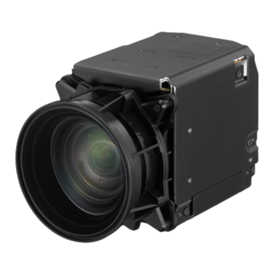
- Seite 1 COLOR CAMERA MODULE FCB-ER8300 FCB-CR8300 SERVICE MANUAL 1st Edition...
- Seite 2 électrique, d’incendie ou de blessure n’effectuer que les réparations indiquées dans le mode d’emploi à moins d’être qualifi é pour en effectuer d’autres. Pour toute réparation faire appel à une personne compétente uniquement. FCB-ER8300/CR8300...
-
Seite 3: Inhaltsverzeichnis
3. Spare Parts 3-1. Notes on Repair Parts ............3-1 3-2. Exploded Views ............... 3-2 4. Diagrams 4-1. Board Location ..............4-1 4-2. Block Diagram ..............4-2 Overall ................4-2 4-3. Frame Wiring..............4-3 Frame Wiring..............4-3 1 (E) FCB-ER8300/CR8300... -
Seite 4: Manual Structure
Manual Structure Purpose of this manual This manual is the Service Manual of the Color Camera Module FCB-ER8300/ CR8300. This manual contains the adjustment, circuit description, spare parts, and diagrams. Related manuals Besides this “Service Manual”, the following manual is available. -
Seite 5: Adjustment
The installer of the Adjust Manual and the installation manual are attached, be sure to confirm the con- tents of them. Be sure to install Adjust Station first. Connection diagram CN701/VC-31 board This unit HD monitor HDMI (CN204) CN201 Personal computer USB (CN205) Tool board J102 (A-2064-388-A) AC adapter (1-468-626-65) 1-1 (E) FCB-ER8300/CR8300... -
Seite 7: Circuit Description
. The SE-1147 board consists of a GYRO sensor, GYRO signal amplifier, and inter-board connection connector. . The SE-1147 board is connected with a VC-31 board using a 6-pin flexible flat cable. . The SE-1147 board outputs the PITCH/YAW analog signal of a GYRO sensor to the VC-31 board. 2-1 (E) FCB-ER8300/CR8300... -
Seite 9: Spare Parts
Therefore, specified parts should be used in the case of な部品です。したがって,交換する時は必ず指定 replacement. の部品を使ってください。 2. Standardization of Parts 2. 部品の共通化 Some repair parts supplied by Sony differ from those ソニーから供給する補修用部品は,セットに使われて used for the unit. These are because of parts common- いるものと異なることがあります。 ality and improvement. これは部品の共通化,改良等によるものです。... -
Seite 10: Exploded Views
Overall 3-2. Exploded Views VC-31 Board (A Side) F5900 FCB-ER8300/CR8300... - Seite 11 3-080-205-21 s SCREW,TAPPING,P2 3-080-206-11 s SCREW, TAPPING, P2 3-080-272-01 s TAPE (A) 4-415-558-01 s SHEET, RADIATION 4-562-114-01 s BOTTOM COVER 4-562-116-01 s THERMAL SHEET (16X16) 4-562-901-01 s SEAL RUBBER VC-31 Board F5900 1-576-874-41 s MICRO FUSE-LINK (1608 TYPE))(2.5A/32V) (2.5A/32V) FCB-ER8300/CR8300...
-
Seite 13: Diagrams
Section 4 Diagrams 4-1. Board Location VC-31 board LD-119 board Sensor module (CMOS) SE-1147 board FCB-ER8300/CR8300... -
Seite 14: Block Diagram
4-2. Block Diagram SE-1147 SE001 IC951 GYRO SENSOR CN951 VC-31 CN803 LENS BLOCK CD-83 IC6000 CN001 CN802 CN701 HDMI OUT CAMERA LENS CMOS SIGNAL VISCA (FP-251) PROCESSOR X601 SENSOR MODULE PureNAND LPDDR2 12MHz CN801 LD-119 CN1001 CN1003 IC001 LENS Driver Overall FCB-ER8300/CR8300... -
Seite 15: Frame Wiring
Frame Wiring Frame Wiring 4-3. Frame Wiring CN601 16P CN804 6P CN702 20P CN001 51P CN802 51P CN701 30P CD-83 VC-31 LENS (FP-251) CN801 50P CN803 6P SE-1147 CN1001 50P CN1003 26P LD-119 Frame Wiring FCB-ER8300/CR8300... - Seite 18 FCB-ER8300 (WW) Printed in Japan Sony Corporation FCB-CR8300 (CN) J, E 2015. 3 32 9-878-638-01 ©2015...


