ASROCK FM2A88M Extreme4+ Schnellinstallationsanleitung
Vorschau ausblenden
Andere Handbücher für FM2A88M Extreme4+:
Inhaltsverzeichnis
Quicklinks
FM2A88M Extreme4+
Version 1.1
Published December 2013
Copyright©2013 ASRock INC. All rights reserved.
Copyright Notice:
No part of this documentation may be reproduced, transcribed, transmitted, or
translated in any language, in any form or by any means, except duplication of
documentation by the purchaser for backup purpose, without written consent of
ASRock Inc.
Products and corporate names appearing in this documentation may or may not
be registered trademarks or copyrights of their respective companies, and are used
only for identification or explanation and to the owners' benefit, without intent to
infringe.
Disclaimer:
Specifications and information contained in this documentation are furnished for
informational use only and subject to change without notice, and should not be
constructed as a commitment by ASRock. ASRock assumes no responsibility for
any errors or omissions that may appear in this documentation.
With respect to the contents of this documentation, ASRock does not provide
warranty of any kind, either expressed or implied, including but not limited to
the implied warranties or conditions of merchantability or fitness for a particular
purpose.
In no event shall ASRock, its directors, officers, employees, or agents be liable for
any indirect, special, incidental, or consequential damages (including damages for
loss of profits, loss of business, loss of data, interruption of business and the like),
even if ASRock has been advised of the possibility of such damages arising from any
defect or error in the documentation or product.
The terms HDMI™ and HDMI High-Definition Multimedia Interface, and the HDMI
logo are trademarks or registered trademarks of HDMI Licensing LLC in the United
States and other countries.
This device complies with Part 15 of the FCC Rules. Operation is subject to the following
two conditions:
(1) this device may not cause harmful interference, and
(2) this device must accept any interference received, including interference that
may cause undesired operation.
CALIFORNIA, USA ONLY
The Lithium battery adopted on this motherboard contains Perchlorate, a toxic substance
controlled in Perchlorate Best Management Practices (BMP) regulations passed by the
California Legislature. When you discard the Lithium battery in California, USA, please
follow the related regulations in advance.
"Perchlorate Material-special handling may apply, see
www.dtsc.ca.gov/hazardouswaste/perchlorate"
ASRock Website: http://www.asrock.com
1
Downloaded from
www.Manualslib.com
manuals search engine
Inhaltsverzeichnis

Verwandte Anleitungen für ASROCK FM2A88M Extreme4+


Inhaltszusammenfassung für ASROCK FM2A88M Extreme4+
- Seite 1 (including damages for loss of profits, loss of business, loss of data, interruption of business and the like), even if ASRock has been advised of the possibility of such damages arising from any defect or error in the documentation or product.
-
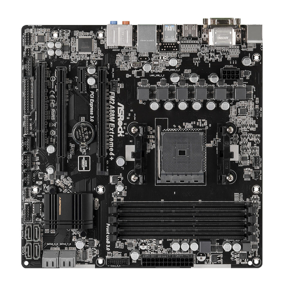
Seite 2: Motherboard-Layout
Motherboard Layout USB 2.0 T: USB3 PWR_FAN1 B: USB4 CPU_FAN2 CPU_FAN1 USB 3.0 T: USB1 B: USB2 USB 2.0 Top: T: USB1 RJ-45 B: USB2 FM2A88M Extreme4+ CHA_FAN1 Front USB 3.0 PCI Express 3.0 PCIE1 CMOS PCIE2 Fast LAN BATTERY Fast USB A88X Fast RAM... - Seite 3 FM2A88M Extreme4+ No. Description Power Fan Connector (PWR_FAN1) ATX 12V Power Connector (ATX12V1) CPU Fan Connector (CPU_FAN1) CPU Fan Connector (CPU_FAN2) 2 x 240-pin DDR3 DIMM Slots (DDR3_A1, DDR3_B1) 2 x 240-pin DDR3 DIMM Slots (DDR3_A2, DDR3_B2) ATX Power Connector (ATXPWR1) USB 3.0 Header (USB3_3_4) Clear CMOS Jumper (CLRCMOS1) 10 SATA3 Connector (SATA3_7)
-
Seite 4: Lan Rj-45 Port
I/O Panel No. Description No. Description USB 2.0 Ports (USB_3_4)* Microphone (Pink) D-Sub Port Optical SPDIF Out Port LAN RJ-45 Port** USB 2.0 Ports (USB_1_2)* USB 3.0 Ports (USB3_1_2) Central / Bass (Orange) (AMD A88X (Bolton-D4)) Rear Speaker (Black) HDMI Port Line In (Light Blue) DVI-D Port Front Speaker (Lime)***... - Seite 5 FM2A88M Extreme4+ * It is recommended to install the USB Keyboard/Mouse cable to USB 2.0 ports (USB_1_2 or USB_3_4) instead of USB 3.0 ports. ** There are two LEDs on the LAN port. Please refer to the table below for the LAN port LED indica- tions.
-
Seite 6: Package Contents
In case any modifications of this manual occur, the updated version will be available on ASRock website without further notice. You may find the latest VGA cards and CPU support lists on ASRock website as well. ASRock website http://www.asrock.com If you require technical support related to this motherboard, please visit our website for specific information about the model you are using. - Seite 7 FM2A88M Extreme4+ 1.2 Specifications Platform - Micro ATX Form Factor - All Solid Capacitor design A-Style - Home Cloud - Supports Socket FM2+ 95W / FM2 100W processors - 4 + 2 Power Phase design Chipset - AMD A88X (Bolton-D4) Memory - Dual Channel DDR3 Memory Technology - 4 x DDR3 DIMM Slots...
- Seite 8 - Supports AMD Steady Video 2.0: New video post processing capability for automatic jitter reduction on home/online video - Supports HDCP with DVI-D and HDMI Ports - Supports Full HD 1080p Blu-ray (BD) playback with DVI-D and HDMI Ports Audio - 7.1 CH HD Audio with Content Protection (Realtek ALC892 Audio Codec) - Premium Blu-ray Audio support...
- Seite 9 Certifications - FCC, CE, WHQL - ErP/EuP ready (ErP/EuP ready power supply is required) * For detailed product information, please visit our website: http://www.asrock.com WARNING Please realize that there is a certain risk involved with overclocking, including adjusting the setting in the BIOS, applying Untied Overclocking Technology, or using third-party overclocking tools.
- Seite 10 4GB for the reservation for system usage un- ® ® der Windows 8 / 7. For Windows 64-bit OS with 64-bit CPU, there is no such limitation. You can use ASRock XFast RAM to ® utilize the memory that Windows cannot use. ®...
-
Seite 11: Unique Features
OC Tweaker and a whole lot more. ASRock Instant Boot ASRock Instant Boot allows you to turn on your PC in just a few seconds, provides a much more efficient way to save energy, time, money, and improves system running speed for your sys- tem. - Seite 12 ASRock XFast RAM ASRock XFast RAM is included in A-Tuning. It fully utilizes the memory space that cannot be used under Windows® 32-bit operating systems. ASRock XFast RAM shortens the loading time of previously visited websites, making web surfing faster than ever.
- Seite 13 ® entering Windows ASRock UEFI System Browser ASRock UEFI system browser is a useful tool included in graphical UEFI. It can detect the devices and configurations that users are currently using in their PC. With the UEFI system browser, you can easily examine the current system configura- tion in UEFI setup.
- Seite 14 ASRock Easy RAID Installer ASRock Easy RAID Installer can help you to copy the RAID driver from a support CD to your USB storage device. After copying the RAID driver to your USB storage device, please change “SATA Mode” to “RAID”, then you can start installing the OS in RAID mode.
- Seite 15 USB Key and let your computer log in to windows automatically! ASRock FAN-Tastic Tuning ASRock FAN-Tastic Tuning is included in A-Tuning. Configure up to five different fan speeds using the graph. The fans will automatically shift to the next speed level when the assigned temperature is met.
-
Seite 16: Cpu Installation
2. Installation This is a Micro ATX form factor motherboard. Before you install the motherboard, study the configuration of your chassis to ensure that the motherboard fits into it. Pre-installation Precautions Take note of the following precautions before you install motherboard components or change any motherboard settings. - Seite 17 FM2A88M Extreme4+ Step 2. Position the CPU directly above the socket such that the CPU corner with the golden triangle matches the socket corner with a small triangle. Step 3. Carefully insert the CPU into the socket until it fits in place. The CPU fits only in one correct orientation.
- Seite 18 2.3 Installation of Memory Modules (DIMM) This motherboard provides four 240-pin DDR3 (Double Data Rate 3) DIMM slots, and supports Dual Channel Memory Technology. 1. For dual channel configuration, you always need to install identical (the same brand, speed, size and chip-type) DDR3 DIMM pairs. 2.
- Seite 19 FM2A88M Extreme4+ Downloaded from www.Manualslib.com manuals search engine...
- Seite 20 2.4 Expansion Slots (PCI and PCI Express Slots) There is 1 PCI slot and 3 PCI Express slots on this motherboard. Before installing an expansion card, please make sure that the power supply is switched off or the power cord is unplugged. Please read the documenta- tion of the expansion card and make necessary hardware settings for the card before you start the installation.
- Seite 21 FM2A88M Extreme4+ 2.5 Jumpers Setup The illustration shows how jumpers are setup. When the jumper cap is placed on pins, the jumper is “Short”. If no jumper cap is placed on pins, the jumper is “Open”. The illustration shows a 3-pin jumper whose pin1 and pin2 are “Short”...
- Seite 22 2.6 Onboard Headers and Connectors Onboard headers and connectors are NOT jumpers. Do NOT place jumper caps over these headers and connectors. Placing jumper caps over the headers and connectors will cause permanent damage of the motherboard! Serial ATA3 Connectors These eight Serial ATA3 (SATA3) connectors support (SATA3_1: see p.2, No.
- Seite 23 FM2A88M Extreme4+ Infrared Module Header This header supports an optional wireless transmitting (5-pin IR1) and receiving infrared module. (see p.2 No. 27) Front Panel Audio Header This is an interface for the front PRESENCE# panel audio cable that allows (9-pin HD_AUDIO1) MIC_RET OUT_RET convenient connection and...
- Seite 24 RESET (Reset Switch): Connect to the reset switch on the chassis front panel. Press the reset switch to restart the computer if the computer freezes and fails to per- form a normal restart. PLED (System Power LED): Connect to the power status indicator on the chassis front panel. The LED is on when the system is operating.
-
Seite 25: Atx Power Connector
FM2A88M Extreme4+ CPU Fan Connectors Please connect the CPU fan FAN_SPEED_CONTROL cable to the connector and (4-pin CPU_FAN1) CPU_FAN_SPEED +12V match the black wire to the (see p.2 No. 3) ground pin. 1 2 3 4 Though this motherboard provides 4-Pin CPU fan (Quiet Fan) support, the 3-Pin CPU fan still can work successfully even without the fan speed control function. - Seite 26 Serial port Header This COM1 header supports a serial port module. (9-pin COM1) (see p.2 No. 26) Chassis Intrusion Header This motherboard supports CASE OPEN detection feature (2-pin CI1) that detects if the chassis cover (see p.2, No. 29) has been removed. This feature requires a chassis with chassis intrusion detection design.
-
Seite 27: Einführung
Wir danken Ihnen für den Kauf des ASRock FM2A88M Extreme4+ Motherboard, ein zuverlässiges Produkt, welches unter den ständigen, strengen Qualitätskontrol- len von ASRock gefertigt wurde. Es bietet Ihnen exzellente Leistung und robustes Design, gemäß der Verpflichtung von ASRock zu Qualität und Halbarkeit. Diese Schnellinstallationsanleitung führt in das Motherboard und die schrittweise Instal-... -
Seite 28: Spezifikationen
1.2 Spezifikationen Plattform - Micro ATX-Formfaktor - Vollständig solides Kondensatordesign A-Stil - Heim-Cloud - Unterstützt Prozessoren für Sockel FM2+ (95 W) / FM2 (100 W) - 4 + 2-Stromphasendesign Chipsatz - AMD A88X (Bolton-D4) Speicher - Unterstützung von Dual-Kanal-Speichertechnologie - 4 x Steckplätze für DDR3 - Unterstützt DDR3 1866/1600/1333/1066 non-ECC, ungepufferter Speicher - Max. -
Seite 29: Rückseite
FM2A88M Extreme4+ - Unterstützt stereoskopisches 3D per Blu-ray mit HDMI - Unterstützt AMD Steady Video 2.0: Neuartige Funktion der Videonachbearbeitung für automatische Reduzierung von Bildschwankungen bei Heim-/Online-Videos - Unterstützt HDCP mit DVI-D- und HDMI-Ports - Unterstutzt 1080p Blu-ray (BD)-Wiedergabe mit DVI-D- und HDMI-Ports Audio - 7.1-Kanal-HD-Audio mit Inhaltsschutz (Realtek ALC892-... -
Seite 30: Zertifizierungen
32-Bit / 8 64-Bit / 7 32-Bit / 7 64-Bit Zertifizierungen - FCC, CE, WHQL - Gemäß Ökodesign-Richtlinie (ErP/EuP) (Stromversorgung gemäß Ökodesign-Richtlinie (ErP/EuP) erforderlich) * Für die ausführliche Produktinformation, besuchen Sie bitte unsere Website: http://www.asrock.com Downloaded from www.Manualslib.com manuals search engine... -
Seite 31: Einstellung Der Jumper
FM2A88M Extreme4+ 1.3 Einstellung der Jumper Die Abbildung verdeutlicht, wie Jumper gesetzt werden. Werden Pins durch Jumperkappen verdeckt, ist der Jumper “Gebrückt”. Werden keine Pins durch Jumperkappen verdeckt, ist der Jumper “Offen”. Die Abbildung zeigt einen 3-Pin Jumper dessen Pin1 und Pin2 “Ge- brückt”... -
Seite 32: Anschlüsse
1.4 Anschlüsse Anschlussleisten sind KEINE Jumper. Setzen Sie KEINE Jumperkappen auf die Pins der Anschlussleisten. Wenn Sie die Jumperkappen auf die Anschlüsse setzen, wird das Motherboard permanent beschädigt! Anschluss Beschreibung Seriell-ATA3-Anschlüsse Diese acht Serial ATA3- (SATA3-)Verbínder (SATA3_1: siehe S.2 - No. 16) unterstützten SATA-Datenkabel (SATA3_2: siehe S.2 - No. - Seite 33 FM2A88M Extreme4+ Infrarot-Modul-Header Dieser Header unterstützt ein optionales, drahtloses Sende- (5-pin IR1) und Empfangs-Infrarotmodul. (siehe S.2 - No. 27) Anschluss für Audio auf Dieses Interface zu einem PRESENCE# der Gehäusevorderseite Audio-Panel auf der Vorder MIC_RET OUT_RET seite Ihres Gehäuses, (9-Pin HD_AUDIO1) ermöglicht Ihnen eine bequeme (siehe S.2 - No.
-
Seite 34: Gehäuselautsprecher-Header
PWRBTN (Ein-/Ausschalter): Zum Anschließen des Ein-/Ausschalters an der Frontblende des Gehäu ses. Sie können konfigurieren, wie das System mit Hilfe des Ein-/Ausschalters ausgeschaltet werden können soll. RESET (Reset-Taste): Zum Anschließen der Reset-Taste an der Frontblende des Gehäuses. Mit der Reset-Taste können Sie den Computer im Falle eines Absturzes neu starten. - Seite 35 FM2A88M Extreme4+ Gehäuse- und Stromlüfteranschlüsse Verbinden Sie die Lüfterkabel mit den Lüfteranschlüssen, (4-pin CHA_FAN1) wobei der schwarze Draht an (siehe S.2, No. 30) den Schutzleiterstift angeschlossenwird. +12V (3-pin PWR_FAN1) PWR_FAN_SPEED (siehe S.2 - No. 1) CPU-Lüfteranschluss Verbinden Sie das CPU - FAN_SPEED_CONTROL Lüfterkabel mit diesem (4-pin CPU_FAN1)
- Seite 36 Obwohl diese Hauptplatine 8-Pin ATX 12V Stromanschluss zur Verfügung stellt, kann sie noch arbeiten, wenn Sie einen traditionellen 4-Pin ATX 12V Energieversorgung adoptieren. Um die 4-Pin ATX Energieversorgung zu verwenden, stecken Sie bitte Ihre Energieversorgung zusammen mit dem Pin 1 und Pin 5 ein. Installation der 4-Pin ATX 12V Energieversorgung COM-Anschluss-Header Dieser COM-Anschluss-...
- Seite 37 FM2A88M Extreme4+ TPM-Stiftleiste Dieser Anschluss unterstützt das Trusted Platform Module- (17-pol. TPMS1) (TPM) System, das Schlüssel, (siehe S.2 - No. 24) digitale Zertifikate, Kennwörter und Daten sicher aufbewahren kann. Ein TPM-System hilft zudem bei der Stärkung der Netzwerksicherheit, schützt digitale Identitäten und gewährleistet die Plattforminteg- rität.
-
Seite 38: Contenu Du Paquet
1. Introduction Merci pour votre achat d’une carte mère ASRock FM2A88M Extreme4+, une carte mère très fiable produite selon les critères de qualité rigoureux de ASRock. Elle offre des performances excellentes et une conception robuste conformément à l’engagement d’ASRock sur la qualité et la fiabilité au long terme. - Seite 39 FM2A88M Extreme4+ 1.2 Spécifications Format - Facteur de forme Micro ATX - Conception à condensateurs solides A-Style - Home Cloud - Prend en charge les processeurs à socket FM2+ 95W / FM2 100W - Conception 4 + 2 Power Phase Chipsets - AMD A88X (Bolton-D4) Mémoire...
- Seite 40 - Prend en charge le D-Sub avec une résolution maximale jusqu’à 1920x1600 @ 60Hz - Prend en charge Lip Sync, Deep Color (12bpc), xvYCC et HBR (High Bit Rate Audio: Audio à haut débit binaire) avec HDMI (Moniteur compatible HDMI requis) - Prend en charge la 3D stéréoscopique Blu-ray avec HDMI - Supporte AMD Steady Video 2.0: Nouvelle fonctionnalité...
- Seite 41 8 64-bit / 7 32-bit / 7 64-bit Certifications - FCC, CE, WHQL - Prêt pour ErP/EuP (alimentation Prêt pour ErP/EuP requise) * Pour de plus amples informations sur les produits, s’il vous plaît visitez notre site web: http://www.asrock.com Downloaded from www.Manualslib.com manuals search engine...
- Seite 42 1.3 Réglage des cavaliers L’illustration explique le réglage des cava- liers. Quand un capuchon est placé sur les broches, le cavalier est « FERME ». Si au- cun capuchon ne relie les broches,le cava- lier est « OUVERT ». L’illustration montre un cavalier à...
- Seite 43 FM2A88M Extreme4+ 1.4 En-têtes et Connecteurs sur Carte Les en-têtes et connecteurs sur carte NE SONT PAS des cavaliers. NE PAS placer les capuchons de cavalier sur ces en-têtes et con- necteurs. Le fait de placer les capuchons de cavalier sur les en- têtes et connecteurs causera à...
- Seite 44 En-tête du module infrarouge Cet en-tête supporte un module infrarouge optionnel de (IR1 br.5) transfert et de réception sans (voir p.2 No. 27) fil. Connecteur audio panneau C’est une interface pour PRESENCE# un câble avant audio en façade (HD_AUDIO1 br. 9) MIC_RET OUT_RET qui permet le branchement et...
- Seite 45 FM2A88M Extreme4+ PWRBTN (Interrupteur d’alimentation): Connectez ici le connecteur d’alimentation sur le panneau avant du châssis. Vous pouvez configurer la façon de mettre votre système hors tension avec l’interrupteur d’alimentation. RESET (Interrupteur de réinitialisation): Connectez ici le connecteur de réinitialisation sur le panneau avant du châssis.
- Seite 46 Connecteur pour châssis et ventilateur Branchez les câbles du ventilateur aux connecteurs pour (CHA_FAN1 br. 4) (voir p.2 No. 30) ventilateur et faites correspondre le fil noir à la broche de terre. (PWR_FAN1 br. 3) +12V PWR_FAN_SPEED (voir p.2 No. 1) Connecteur du ventilateur Veuillez connecter le câble de FAN_SPEED_CONTROL...
- Seite 47 FM2A88M Extreme4+ Connecteur ATX 12V Veuillez connecter une unité d’alimentation électrique ATX (ATX12V1 br.8) 12V sur ce connecteur. (voir p.2 No. 2) Bien que cette carte mère possède 8 broches connecteur d’alimentation ATX 12V, il peut toujours travailler si vous adoptez une approche traditionnelle à...
- Seite 48 Embase TPM Ce connecteur prend en charge un module TPM (Trusted Plat- (TPMS1 17 broches) form Module – Module de (voir p.2 No. 24) plateforme sécurisée), qui permet de sauvegarder clés, certificats numériques, mots de passe et données en toute sécurité.
-
Seite 49: Contenuto Della Confezione
1. Introduzione Grazie per aver scelto una scheda madre ASRock FM2A88M Extreme4+, una scheda madre affidabile prodotta secondo i severi criteri di qualità ASRock. Le prestazioni eccellenti e il design robusto si conformano all’impegno di ASRock nella ricerca della qualità e della resistenza. - Seite 50 1.2 Specifiche Piattaforma - Micro ATX Form Factor - Design di condensatore solido Stile superiore - Home Cloud Processore - Supporto per processori socket FM2+ 95W / FM2 100W - Struttura di fase con alimentazione 4 + 2 Chipset - AMD A88X (Bolton-D4) Memoria - Supporto tecnologia Dual Channel Memory - 4 x slot DDR3 DIMM...
- Seite 51 FM2A88M Extreme4+ (è necessario un monitor compatibile HDMI) - Supporta Blu-ray Stereoscopico in 3D con HDMI - Supporta AMD Steady Video 2.0: Nuova capacità di post-elab orazione video per la riduzione automatica delle vibrazioni nei video a casa/on-line - Supporto della funzione HDCP con le porte DVI-D e HDMI - Supporto 1080p Blu-ray (BD) riproduzione con le porte DVI-D e HDMI Audio...
- Seite 52 7 32 bit / 7 64 bit Certificazioni - FCC, CE, WHQL - Predisposto ErP/EuP (è necessaria l’alimentazione predis posta per il sistema ErP/EuP) * Per ulteriori informazioni, prego visitare il nostro sito internet: http://www.asrock.com Downloaded from www.Manualslib.com manuals search engine...
- Seite 53 FM2A88M Extreme4+ 1.3 Setup dei Jumpers L’illustrazione mostra come sono settati i jump- er. Quando il ponticello è posizionato sui pin, il jumper è “CORTOCIRCUITATO”. Se sui pin non ci sono ponticelli, il jumper è “APERTO”. L’illustrazione mostra un jumper a 3 pin in cui il pin1 e il pin2 sono “CORTOCIRCUITATI”...
- Seite 54 1.4 Collettori e Connettori su Scheda I collettori ed i connettori su scheda NON sono dei jumper. NON instal- lare cappucci per jumper su questi collettori e connettori. L’installazione di cappucci per jumper su questi collettori e connettori provocherà danni permanenti alla scheda madre! Connettori Serial ATA3 Questi otto connettori Serial ATA3 (SATA3) supportano cavi...
- Seite 55 FM2A88M Extreme4+ Collettore modulo infrarossi Questo collettore supporta moduli ad infrarossi optional (5-pin IR1) per la trasmissione e la (vedi p.2 Nr. 27) ricezione senza fili. Connettore audio sul È un’interfaccia per il cavo del PRESENCE# pannello frontale pannello audio. Che consente MIC_RET OUT_RET connessione facile e controllo...
- Seite 56 PWRBTN (interruttore d’alimentazione): Va collegato all’interruttore d’alimentazione del pannello frontale del telaio. Usando l’interruttore d’alimentazione si può configurare il modo in cui si spegne il sistema. RESET (interruttore di ripristino): Va collegato all’interruttore di ripristino del pannello frontale del telaio. Premere l’interruttore di ripristino per riavviare il sistema se il computer si blocca e non riesce ad eseguire un normale riavvio.
- Seite 57 FM2A88M Extreme4+ Connettore ventolina CPU Collegare il cavo della ventolina FAN_SPEED_CONTROL CPU a questo connettore e far (4-pin CPU_FAN1) CPU_FAN_SPEED +12V combaciare il filo nero al pin (vedi p.2 Nr. 3) terra. 1 2 3 4 Sebbene la presente scheda madre disponga di un supporto per ventola CPU a 4 piedini (ventola silenziosa), la ventola CPU a 3 piedini è...
- Seite 58 Collettore porta COM Questo collettore porta COM è utilizzato per supportare il (9-pin COM1) modulo porta COM. (vedi p.2 Nr. 26) Header di intrusione dello chassis Questa scheda madre supporta la funzione di rilevamento del (2-pin CI1) CASE APERTOche rileva che (vedi p.2 Nr.
-
Seite 59: Contenido De La Caja
FM2A88M Extreme4+ 1. Introducción Gracias por su compra de ASRock FM2A88M Extreme4+ placa madre, una placa de confianza producida bajo el control de calidad estricto y persistente. La placa madre provee realización excelente con un diseño robusto conforme al compromiso de calidad y resistencia de ASRock. - Seite 60 1.2 Especificación Plataforma - Factor forma Micro ATX - Diseño de los Condensadores: All Solid A-Style - Home Cloud Procesador - Admite zócalos de procesadores FM2+ 95W / FM2 100W - Diseño de fases de potencia 4 + 2 Chipset - AMD A88X (Bolton-D4) Memoria - Soporte de Tecnología de Memoria de Doble Canal...
- Seite 61 FM2A88M Extreme4+ - Admite la función 3D estereoscópica Blu-ray con HDMI - Admite AMD Steady Video 2.0: Nueva capacidad de pospro cesamiento de vídeo para reducción automática de oscila ciones en vídeo doméstico y en línea - Admite la función HDCP con puertos DVI-D y HDMI - Apoya la reproducción de Blu-rayo de 1080p (BD) con puertos DVI-D y HDMI Audio...
- Seite 62 - FCC, CE, WHQL - Cumple con la directiva ErP/EuP (se requiere una fuente de alimentación que cumpla con la directiva ErP/EuP) * Para más información sobre los productos, por favor visite nuestro sitio web: http://www.asrock.com Downloaded from www.Manualslib.com manuals search engine...
- Seite 63 FM2A88M Extreme4+ 1.3 Setup de Jumpers La ilustración muestra como los jumpers son configurados. Cuando haya un jumper- cap sobre los pins, se dice gue el jumper está “Short”. No habiendo jumper cap sobre los pins, el jumper está “Open”. La ilus- tración muesta un jumper de 3 pins cuyo pin 1 y pin 2 están “Short”.
- Seite 64 1.4 Cabezales y Conectores en Placas Los conectores y cabezales en placa NO son puentes. NO coloque las cubiertas de los puentes sobre estos cabezales y conectores. El colocar cubiertas de puentes sobre los conectores y cabezales provo- cará un daño permanente en la placa base. Conexiones de serie ATA3 Estas ocho conexiones de serie ATA3 (SATA3) admiten...
- Seite 65 FM2A88M Extreme4+ Cabezal de Módulo Infrarrojos Este cabezal soporta un módulo infrarrojos de (5-pin IR1) transmisión y recepción (vea p.2, N. 27) wireless opcional. Conector de audio de Este es una interface para PRESENCE# panel frontal cable de audio de panel frontal MIC_RET OUT_RET que permite conexión y control...
- Seite 66 RESTABLECER (interruptor de restablecimiento): Conecte el interruptor de restablecimiento situado en el panel frontal del chasis. Pulse el interruptor de restablecimiento para restablecer el equipo si se bloquea y no se reinicia con normalidad. PLED (LED de alimentación del sistema): Conecte el indicador de estado de alimentación situado en el panel frontal del chasis.
- Seite 67 FM2A88M Extreme4+ Conector del ventilador Conecte el cable del ventilador FAN_SPEED_CONTROL de la CPU de la CPU a este conector y CPU_FAN_SPEED +12V haga coincidir el cable negro (4-pin CPU_FAN1) con el conector de tierra. (vea p.2, N. 3) 1 2 3 4 Aunque esta placa base proporciona compatibilidad para un ventilador (silencioso) de procesador de 4 contactos, el ventilador de procesador de 3 contactos seguirá...
- Seite 68 Aunque esta placa base proporciona un conector de energía de 8-pin ATX 12V, puede todavía trabajar si usted adopta un fuente tradicional de energía de 4-pin ATX 12V. Para usar el fuente de energía de 4-pin ATX 12V, por favor conecte su fuente de energía junto con Pin 1 y Pin 5.
- Seite 69 FM2A88M Extreme4+ 1. Введение Благодарим вас за покупку материнской платы ASRock FM2A88M Extreme4+ надежной материнской платы, изготовленной в соответствии с постоянно предъявляемыми ASRock жесткими требованиями к качеству. Она обеспечивает превосходную производительность и отличается отличной конструкцией, которые отражают приверженность ASRock качеству...
- Seite 70 1.2 Спецификации Платформа - форм-фактор Micro ATX - Использование только твердотельных конденсаторов A-Style - Home Cloud Процессор - Поддержка разъема FM2+ 95 Вт / процессоров FM2 100 Вт - Технология 4 + 2 Power Phase Design Набор микросхем - AMD A88X (Bolton-D4) Память...
- Seite 71 FM2A88M Extreme4+ - Поддержка технологии AMD Steady Video 2.0: новая функция постобработки видеоизображения для автоматического устранения дрожания при просмотре домашних и онлайновых видеозаписей - Поддержка функции HDCP через разъемы DVI-D и HDMI - Подержат Blu-луч 1080p (КОММУТАЦИОННАЯ ДОСКА) через разъемы DVI-D и HDMI Аудиосистема...
- Seite 72 / 8 64-bit / 7 32-bit / 7 64-bit ные системы - FCC, CE, WHQL Сертификаты - Совместимость с ErP/EuP Ready (требуется блок питания совместимый с ErP/EuP) * Для детальной информации продукта, пожалуйста посетите наш вебсайт: http://www.asrock.com Downloaded from www.Manualslib.com manuals search engine...
- Seite 73 FM2A88M Extreme4+ 1.3 Установка перемычек Конфигурация перемычек иллюстрируется на рисунке. Когда перемычка надета на контакты, они называются “замкнутыми” (short). Если на контактах перемычки нет, то они называются “разомкнутыми” (open). На иллюстрации показана 3-контактная перемычка, у которой контакты 1 и 2 замкнуты.
- Seite 74 1.4 Колодки и разъемы на плате Имеющиеся на плате колодки и разъемы НЕ ЯВЛЯЮТСЯ контактами для перемычек. НЕ УСТАНАВЛИВАЙТЕ перемычки на эти колодки и разъемы – это приведет к необратимому повреждению материнской платы! Разъемы Serial ATA3 восемь соединителя Serial ATA3 предназначаются...
- Seite 75 FM2A88M Extreme4+ Колодка инфракрасного модуля Данная колодка позволяет подключить дополнительный (5-контактный IR1) модуль беспроводного (см. стр. 2, п. 27) инфракрасного приемопередатчика. Аудиоразъем передней Этот интерфейс предназначен PRESENCE# панели для присоединения MIC_RET OUT_RET аудиокабеля передней панели, (9-контактный HD_AUDIO1) обеспечивающего удобное (см. cтр. 2, п. 28) подключение...
- Seite 76 PWRBTN (кнопка питания): Подключите к этим контактам кнопку питания на передней панели корпуса. Способ выключения системы с помощью кнопки питания можно настроить. RESET (кнопка сброса): Подключите к этим контактам кнопку сброса на передней панели корпуса. Нажмите кнопку сброса для перезагрузки компьютера, если компьютер...
- Seite 77 FM2A88M Extreme4+ Разъем вентилятора Подключите к этому разъему FAN_SPEED_CONTROL процессора кабель вентилятора процессора CPU_FAN_SPEED так, чтобы черный провод (4-контактный CPU_FAN1) +12V соответствовал контакту земли. (см. стр. 2, п. 3) 1 2 3 4 Данная материнская плата поддерживает вентиляторы процессора с 4-контактным разъемом (функция тихого режима вентилятора), однако...
- Seite 78 Хотя эта объединительная плата обеспечивает ATX с 8 булавками 12V соединитель власти, это может все еще работать, если Вы принимаете традиционный ATX с 4-Pin 12V электропитание. Чтобы использовать электропитание ATX с 4-Pin, пожалуйста включите ваше электропитание наряду с Булавкой 1 и Прикрепите 5. ATX С...
- Seite 79 Gratos por comprar nossa placa–mãe FM2A88M Extreme4+ um produto confiável feito com ASRock um estrito controle de qualidade consistente. Com um excelente desempenho, essa placa é dotada de um projeto robusto que atende a ASRock de compromisso com a qualidade e durabilidade.
-
Seite 80: Especificações
1.2 Especificações Plataforma - Formato Micro ATX - Design de condensador sólido Estilo A - Home Cloud - Suporta processadores com Socket FM2+ a 95W / FM2 a 100W - Alimentação de 4 + 2 fases Chipsets - AMD A88X (Bolton-D4) Memória - Suporte à... - Seite 81 FM2A88M Extreme4+ HBR (áudio de taxa de bits elevada) com HDMI (é necessário um monitor compatível com a norma HDMI) - Suporta 3D Estereoscópico Blu-ray com HDMI - Suporta AMD Steady Video 2.0: Nova capacidade de pós-processamento de vídeo para redução automática de vibrações em vídeo local/online - Suporta função HDCP com portas DVI-D e HDMI - Suporta a norma Blu-ray de alta definição 1080p (BD) com...
- Seite 82 / 8 de 64 bits / 7 de 32 bits / 7 de 64 bits Certificações - FCC, CE, WHQL - “ErP/EuP Ready” (é necessária alimentação eléctrica “ErP/ EuP Ready”) * Para informações mais detalhadas por favor visite o nosso sítio Web: http://www.asrock.com Downloaded from www.Manualslib.com manuals search engine...
- Seite 83 FM2A88M Extreme4+ 1.3 Configuração dos Jumpers A ilustração mostra como os jumpers são configurados. Quando há uma capa de jumpers sobre os pinos, diz–se que o jump- er está “curto”. Não havendo capa sobre os pinos, o jumper está “aberto”. A ilustração mostra um jumper de 3 pinos em que os pinos 1 e 2 están “curtos”...
- Seite 84 1.4 Conectores Os conectores NÃO SÃO jumpers. NÃO coloque capas de jumper sobre estes conectores. A colocação de pontos de jumper sobre os conectores causará danos irreversíveis à placa-mãe. Conectores ATA3 Serial Estes oito conectores Serial ATA (SATA3) suportam (SATA3_1: veja a folha 2, No. 16) unidades de disco rígido SATA (SATA3_2: veja a folha 2, No.
- Seite 85 FM2A88M Extreme4+ Conector do módulo Este conector suporta um de infravermelho módulo de infravermelho para transmissão e recepção sem (IR1 de 5 pinos) fio, opcional. (veja a folha 2, No. 27) Conector Áudio do painel Esta é uma interface para o PRESENCE# frontal cabo de áudio no painel frontal,...
- Seite 86 RESET (Botão de reposição): Ligue ao botão de reposição no painel frontal do chassis. Prima o botão de reposição para reiniciar o computador caso este bloqueie e não seja possível reiniciar normalmente. PLED (LED de alimentação do sistema): Ligue ao indicador do estado da alimentação no painel frontal do chassis. O LED ficará...
- Seite 87 FM2A88M Extreme4+ Conector do ventilador da Ligue o cabo do ventilador da FAN_SPEED_CONTROL CPU, coincidindo o fio preto CPU_FAN_SPEED +12V com o pino de aterramento. (CPU_FAN1 de 4 pinos) (veja a folha 2, No. 3) 1 2 3 4 Apesar de esta placa-mãe possuir 4 apoios para uma ventoinha de CPU (Ventoinha silenciosa), uma ventoinha de 3 pinos para CPU poderá...
- Seite 88 Conector de porta de série Este conector COM1 suporta um módulo de porta de série. (COM1 de 9 pinos) (veja a folha 2, No. 26) Conector de intrusão no chassis Esta placa principal suporta a função de detecção de (CI1 de 2 pinos) ABERTURA da CAIXA (veja a folha 2, No.
- Seite 89 önceden haber verilmeksizin değişebilir. Bu belgede değişiklik yapılması durumun -da, güncelleştirilmiş sürüm ayrıca haber verilmeksizin ASRock web sitesinde sunulur. En son VGA kartlarını ve CPU destek listelerini de ASRock web sitesinde bulabilirsiniz. ASRock web sitesi http://www.asrock.com Bu anakartla ilgili teknik desteğe ihtiyacınız olursa, kullandığınız modele özel bilgiler için lütfen web sitemizi ziyaret edin.
- Seite 90 1.2 Özellikler Platform - Mikro ATX Form Faktörü - Tam Katı Bağlayıcı tasarımı A-Stili - Ev Bulutu - Yuva FM2+ 95W / FM2 100W işlemciler için destek - 4 + 2 Güç Fazı Tasarımı Yonga seti - AMD A88X (Bolton-D4) Bellek - Çift Kanallı...
- Seite 91 FM2A88M Extreme4+ - AMD Steady Video 2.0’yu destekler: Ev/çevrimiçi videoda otomatik titreşim azaltma için yeni video işleme sonrası özelliği - DVI-D ve HDMI portlarэyla HDCP iюlevini destekler - DVI-D ve HDMI portlarэyla Tam HD 1080p Blu-ray (BD) oynatэmэnэ destekler - İçerik Koruma Özelliği ile 7.1 CH HD Ses (Realtek ALC892 Ses Codec Bileşeni) - Üstün Blu-ray ses desteği - PCIE x1 Gigabit LAN 10/100/1000 Mb/s...
- Seite 92 8.1 32-bit / 8.1 64-bit / 8 32-bit / 8 64-bit / 7 32-bit / 7 64-bit Sertifikalar - FCC, CE, WHQL - ErP/EuP Hazır (ErP/EuP hazır güç kaynağı gerekli) * Ayrıntılı ürün bilgileri için lütfen web sitemizi ziyaret edin: http://www.asrock.com Downloaded from www.Manualslib.com manuals search engine...
- Seite 93 FM2A88M Extreme4+ 1.3 Jumper'ların Ayarı Şekilde jumper'ların nasıl ayarlandıkları gösterilmektedir. Jumper kapağı pinler üzerine yerleştirildiğinde jumper "Kapalı" dır. Jumper kapağı pinler üzerindeyken jumper "Açık" tır. Şekilde pin1 ve pin2'si "Kapalı" olan jumper kapağı bu 2 pine yerleştirilmiş 3-pinli jumper gösterilmektedir. Jumper Ayar CMOS’u temizleme...
- Seite 94 1.4 Yerleşik Fişler ve Konektörler Yerleşik fişler ve konektörler jumper DEĞİLDİR. Bu fişlerin ve konektörlerin üzerine jumper kapakları YERLEŞTİRMEYİN. Fişlerin ve konektörlerin üzerine jumper kapakları yerleştirmek anakartın kalıcı olarak zarar görmesine neden olabilir! Seri ATA3 Konektörler Bu sekiz Seri ATA3 (SATA3) konektör, dahili depolama (SATA3_1: bkz.
- Seite 95 FM2A88M Extreme4+ Kızılötesi Modülü Fişi Bu fiş, isteğe bağlı bir kablosuz aktarma ve alma kızılötesi (5-pinli IR1) modülünü destekler. (bkz. S.2 No. 27) Ön Panel Ses Fişi Bu, panel ses kablosu için PRESENCE# uygun bağlantı sağlayan ve (9-pinli HD_AUDIO1) MIC_RET OUT_RET ses cihazlarını...
- Seite 96 PLED (Sistem Gücü LED’i): Kasa üzerindeki güç durumu göstergesini ön panele bağlayın. Sistem çalışırken LED yanar. Sistem S1 uyku modunda iken LED yanıp sön meye devam eder. Sistem S3/S4 uyku modunda veya kapalı (S5) iken LED söner. HDLED (Sabit Disk Çalışma LED’i): Kasa üzerindeki sabit disk çalışma LED'ini ön panele bağlayın.
- Seite 97 FM2A88M Extreme4+ Bu anakart 4-Pinli CPU fan (Sessiz Fan) desteği sağlasa da, 3-Pinli CPU fan hızı kontrol işlevi olmadan bile hala başarılı bir şekilde çalışabilir. 3-Pinli CPU fanı bu konektördeki CPU fan konektörüne bağlamayı planlıyorsanız, lütfen Pin 1-3'e bağlayın. Pin 1-3 Bağlı 3-Pinli Fanı...
- Seite 98 Kasaya Yetkisiz Erişim Fişi Bu anakart, kasa kapağının çıkarılıp çıkarılmadığını (2-pinli CI1) algılayan KASA AÇIK algılama (bkz. S.2 No. 29) özelliğini destekler. Bu özellik, kasaya yetkisiz erişim tasarımına sahip bir kasa gerektirir. Yazdırma Portu Fişi Bu, yazdırma portu kablosu için AFD# ERROR# yazıcı...
- Seite 99 립니다 . 이 메인보드는 엄격한 품질관리 하에 생산되어진 신뢰성 있는 메인보드 입니 다 . 이 제품은 고 품격 디자인과 함께 ASRock 의 우수한 품질과 최고의 안정성을 자 랑하고 있습니다 . 이 빠른 설치 안내서에는 마더보드에 대한 설명과 단계별 설치 방...
- Seite 100 1.2 설명서 플랫폼 - Micro ATX 폼 팩터 - 모든 솔리드 콘덴서 구조 A- 스타일 - 홈 클라우드 - 소켓 FM2+ 95W / FM2 100W 프로세서에 대한 지원 - 4 + 2 전원 위상 디자인 칩셋 - AMD A88X (Bolton-D4) 메모리...
- Seite 101 FM2A88M Extreme4+ 오디오 - 콘텐츠 보호를 이용한 7.1 CH HD 오디오 지원 (Realtek ALC892 오디오 코덱 ) - 프리미엄 Blu-ray 오디오 지원 랜 - PCIE 1 개 , Gigabit LAN 10/100/1000 Mb/s ® ® - Qualcomm Atheros AR8171 ® ® - Qualcomm Atheros 보안...
- Seite 102 8.1 32 비트 /8.1 64 비트 /8 32 비트 /8 64 비트 /7 32 비트 /7 64 비트 인증서 - FCC, CE, WHQL - ErP/EuP 지원 (ErP/EuP 지원 전원 공급기가 요구됨 ) * 상세한 제품정보는 당사의 웹사이트를 방문할수있습니다 . http://www.asrock.com Downloaded from www.Manualslib.com manuals search engine...
- Seite 103 FM2A88M Extreme4+ 1.3 점퍼 셋팅 그림은 점퍼를 어떻게 셋업 하는지를 보여줍니다 . 점퍼 캡이 핀 위에 있을 때 , 점퍼는 “ 쇼트 ” 입니다 . 점퍼 캡이 핀 위에 없을 때 점퍼는 “ 오픈 ” 입니다 . 그림은 3 개의 핀 중 1-2 번 핀이 “ 쇼트 ” 임을 보여주는...
- Seite 104 1.4 온보드 헤더 및 커넥터 주의 ! 이 콘넥터는 점퍼가 아닙니다 . 이 콘넥터 위에 점퍼 캡을 사용하지마 세요 . 커넥터에 점퍼 캡을 설치하면 마더보드가 영구적으로 손상됩니다 ! 시리얼 ATA3 커넥터 8 개의 시리얼 ATA3 (SATA3) 커넥터는 내부 저장 (SATA3_1: 2 페이지 , 16 번 항목 참조 ) 장치용...
- Seite 105 FM2A88M Extreme4+ 적외선 모듈 헤더 이 헤더는 선택품목인 무선 적외선 송수신 모듈을 (5 핀 IR1) 지원합니다 . (2 페이지 , 27 번 항목 참조 ) 전면부 오디오 콘넥터 이 콘넥터는 오디오 장치를 PRESENCE# 편리하게 조절하고 연결할 수 (9 핀 HD_AUDIO1) MIC_RET OUT_RET 있는...
- Seite 106 RESET( 리셋 스위치 ): 섀시 전면 패널의 리셋 스위치에 연결합니다 . 컴퓨터가 정지하고 정상적 재시작을수행하지 못할 경우 리셋 스위치를 눌러 컴퓨터를 재시작합니 다 . PLED( 시스템 전원 LED): 섀시 전면 패널의 전원 상태 표시등에 연결합니다 . 시스템이 작동하고 있 을 때는 LED 가 켜져 있습니다 . 시스템이 S1 대기 상태에 있을 때는 LED 가...
- Seite 107 FM2A88M Extreme4+ CPU 팬 커넥터 CPU 팬 케이블을 이 커넥터에 FAN_SPEED_CONTROL 연결하고 흑색 선을 접지 핀에 (4 핀 CPU_FAN1) CPU_FAN_SPEED +12V 맞추십시오 . (2 페이지 , 3 번 항목 참조 ) 1 2 3 4 본 머더보드가 4 핀 CPU 팬 ( 저소음 팬 ) 지원을 제공하기는 하지만 팬 속 도...
- Seite 108 시리얼포트 컨넥터 이 콘넥터는 시리얼 포트 모듈을 지원합니다 . (9 핀 COM1) (2 페이지 , 26 번 항목 참조 ) 섀시 침입 헤더 이 메인보드는 섀시 커버가 제 거되면 이를 감지하는 케이스 (2 핀 CI1) 열림 감지 기능을 지원합니다 . (2 페이지...
- Seite 109 ポートリストもウェブサイトでご覧になれます。ASRock 社ウェブサイト: http://www.asrock.com このマザーボードに関連する技術サポートが必要な場合、当社の Web サイト にアクセスし、使用しているモデルについての特定情報を見つけてくださ い。 www.asrock.com/support/index.asp 1.1 パッケージ内容 ASRock FM2A88M Extreme4+ マザーボード (Micro ATX フォームファクター ) ASRock FM2A88M Extreme4+ クイックインストレーションガイド ASRock FM2A88M Extreme4+ サポート CD 2 x シリアル ATA (SATA) データケーブル(オプション) 1 x I/O パネルシールド Downloaded from www.Manualslib.com...
- Seite 110 1.2 仕様 プラットフ - Micro ATX フォームファクター - オール固体コンデンサー設計 A スタイル - Home Cloud - Socket FM2+ 95W / FM2 100W プロセッサのサポート - 4 + 2 電源位相設計 ヱップセット - AMD A88X (Bolton-D4) メモリー - デュアルヱャンネル DDR3 メモリーテクノロジー - DDR3 DIMM スロット x 4 - DDR3 1866/1600/1333/1066 non-ECC, un-buffered メモリーに対応...
- Seite 111 FM2A88M Extreme4+ - AMD Steady Video 2.0 のサポート: 家庭 / オンラインビデ オの自動ジッター低減用の新しいビデオポストの処理機能 - HDCP 機能、DVI-D ポートおよび HDMI ポートをサポート - 1080p Blu-ray (BD) 再生サポート、DVI-D ポートおよび HDMI ポートをサポート オーディオ - 7.1 CH HD オーディオ、コンテンツプロテクション付き(Realtek ALC892 オーディオコーデック) - プレミアムブルーレイオーディオサポート - PCIE x1 ギガビット LAN 10/100/1000 Mb/ 秒 ®...
- Seite 112 Windows 8.1 32-bit / 8.1 64-bit / 8 32- bit / 8 64-bit / 7 32-bit / 7 64-bit ® 認証 - FCC, CE, Microsoft WHQL 認証済み - ErP/EuP 対応(ErP/EuP 対応の電源装置が必要です) * 製品の詳細については、http://www.asrock.com を御覧なさい。 Downloaded from www.Manualslib.com manuals search engine...
- Seite 113 FM2A88M Extreme4+ 1.3 ジャンパ設定 右の図はジャンパがどのように設定されているかを示しま す。ジャンパキャップがピンに置かれている場合、ジャンパ は “ショート” になります。ジャンパキャップがピンに置か れていない場合、ジャンパ は “オープン”になります。右の 図で、3ピンジャンパで、1-2 ピンを “ショート”の場合、こ れらの2つのピンにジャンパキャップを置きます。 ジャンパ 設定 説明 CMOS の消去ジャンパ (CLRCMOS1) ( ページ 2 アイテム 9 参照) CMOS の消去 デフォルト設定 注 : CLRCMOS1 により、CMOS のデータをクリアできます。システムパラメータをクリアしデフォルト設定にリ セットするには、コンピュータの電源をオフにし、電源装置から電源コードを抜いてください。15 秒待って から、ジャンパキャップを使用して CLRCMOS1 のピン 2 とピン 3 を 5 秒間ショートしてください。ただし、 BIOS 更新の後すぐには...
- Seite 114 1.4 オンボードのヘッダとコネクタ類 オンボードのヘッダとコネクタ類はジャンパではありません。それらのヘッ ダやコネクタにジャンパキャップをかぶせないでください。ヘッダやコネクタ にジャンパキャップをかぶせると、マザーボードに深刻な影響を与える場 合があります。 シリアル ATA3 コネクタ これら 8 本のシリアル ATA3 (SATA3)コネクタは内蔵スト SATA3_1: ページ 2, アイテム 16 を参照 レーデバイスに使用する SATA SATA3_2: ページ 2, アイテム 17 を参照 データケーブルに対応していま SATA3_3: ページ 2, アイテム 15 を参照 す。現在の SATA3 インタフェー SATA3_4: ページ 2, アイテム 14 を参照 スの最大データ転送速度は...
- Seite 115 FM2A88M Extreme4+ 赤外線モジュールコネクタ このコネクタは赤外線の無線送受信 モジュールに対応します。 (5 ピン IR1) ページ 2, アイテム 27 を参照 フロントオーディオパネルコネクタ このコネクタは、オーディオ機器 PRESENCE# との便利な接続とコントロールを (9 ピン HD_AUDIO1) MIC_RET OUT_RET 可能にするフロンとオーディオパ ページ 2, アイテム 28 を参照 ネルのためのインターフェイスで す。 OUT2_L J_SENSE OUT2_R MIC2_R MIC2_L ハイディフィニションオーディオはジャックセンシングをサポー トしますが、正しく機能するためにシャーシのパネルワイヤが HAD をサポートする必要があります。このマニュアルとシャー シのマニュアルの指示に従って、システムを取り付けてくださ い。...
- Seite 116 シャーシに付いている電源スイッチ、リセットスイッチ、システムステータ スインジケータを下記のピン割り当て指示に従ってこのヘッダに接続します。 ケーブルを接続する前にピンの正負極性にご注意ください。 PWRBTN ( 電源スイッチ ): 前面パネルに付いている電源スイッチに接続します。電源スイッチによるシス テム電源オフ方法を設定して変更することも可能です。 RESET ( リセットスイッヱ ): シャーシの前面パネルに付いているリセットスイッチに接続します。コン ピュータがフリーズし、正常な再起動をしない場合は、リセットスイッチを 押してコンピュータを再起動します。 PLED ( システム電源 LED): シャーシの前面パネルに付いている電源ステータスインジケータに接続しま す。LED は、システムが動作しているときに点灯します。LED はシステム が S1 スリープ状態のときに点滅します。システムが S3 または S4 スリープ状 態になるか、電源オフ (S5) になると、LED は消灯します。 HDLED ( ハードドライブアクティビティ LED): シャーシの前面パネルに付いているハードドライブアクティビティ LED に接続 します。LED は、ハードドライブがデータの読み込みまたは書き込み動作を...
- Seite 117 FM2A88M Extreme4+ ファンケーブルをファンコネクタ シャーシおよび電源ファンコネクタ に接続し、黒いワイヤをアースピ (4 ピン CHA_FAN1) ンに合わせてください。 ページ 2, アイテム 30 を参照 (3 ピン PWR_FAN1) +12V ページ 2, アイテム 1 を参照 PWR_FAN_SPEED CPU ファンコネクタ このコネクタには CPU ファンケー FAN_SPEED_CONTROL ブルを接続します。黒いコードは (4 ピン CPU_FAN1) CPU_FAN_SPEED +12V アースピンに接続してください。 ページ 2, アイテム 3 を参照 1 2 3 4 このマザーボードでは...
- Seite 118 ATX 12V コネクタ このコネクタには CPU に Vcore 電 源を供給できるように、ATX 12V (8 ピン ATX12V1) プラグを備えたサワーサプライを ページ 2, アイテム 2 を参照 接続する必要があることに注意し てください。接続に問題があると、電源 は正しく供給されません。 このマザーボードで 8-pin ATX 12V 電源コネクタが提供されたが、 従来の 4-pin ATX 12V 電源でも動作できます。 4-pin ATX 電源を使用する場合、電源を Pin 1 と Pin 5 とともに差し込んでください。 4-Pin ATX 12V 電源の取り付け...
- Seite 119 謝謝你采用了華擎 FM2A88M Extreme4+ 主板 , 本主板由華擎嚴格制造 , 質量可靠 , 穩定性好 , 能夠獲得卓越的性能。本安裝指南介紹了安裝主板的步驟。更加詳細的主 板信息可參看驅動光盤的用戶手冊。 由于主板規格和 BIOS 軟件將不斷升級 , 本手冊之相關內容變更恕不另 行通知。請留意華擎网站上公布的升級版本。你也可以在華擎網站找 到最新的顯卡和 CPU 支持表。 華擎网址:http://www.asrock.com 如果您需要與此主板有關的技術支持 , 請參觀我們的網站以了解您使用機 種的規格信息。 www.asrock.com/support/index.asp 1.1 包裝盒內物品 華擎 FM2A88M Extreme4+ 主板 (Micro ATX 規格 ) 華擎 FM2A88M Extreme4+ 快速安裝指南...
- Seite 120 1.2 主板規格 架构 - Micro ATX 規格 - 全固態電容器設計 A-Style - 家庭云 處理器 - 支持 Socket FM2+ 95W / FM2 100W 處理器 - 4 + 2 電源相位設計 芯片組 - AMD A88X (Bolton-D4) 系統內存 - 支持雙通道 DDR3 內存技術 - 配備 4 個 DDR3 DIMM 插槽 - 支持...
- Seite 121 FM2A88M Extreme4+ 音效 - 具有內容保護功能的 7.1 CH 高清音頻 (Realtek ALC892 音頻 編解碼器) - 优質 Blu-ray 音頻支持 板載 LAN 功能 - PCIE x1 Gigabit LAN 10/100/1000 Mb/s ® ® - Qualcomm Atheros AR8171 ® ® - 支持 Qualcomm Atheros 网上安全喚醒技術 - 支持 Wake-On-LAN (网上喚醒) - 支持高能效以太网...
- Seite 122 8.1 32 位元 /8.1 64 位元 /8 32 位元 / 8 64 位元 /7 32 位元 /7 64 位元适用于此主板 認證 - FCC, CE, WHQL - 支持 ErP/EuP( 需要同時使用支持 ErP/EuP 的電源供應器 ) * 請參閱華擎網站了解詳細的產品信息 : http://www.asrock.com Downloaded from www.Manualslib.com manuals search engine...
- Seite 123 FM2A88M Extreme4+ 1.3 跳線設置 插圖所示的就是設置跳線的方法。當跳線 帽 放 置 在 針 腳 上 時 , 這 個 跳 線 就 是“ 短 接”。如果針腳上沒有放置跳線帽 , 這個 跳線就是“開路”。插圖顯示了一個 3 針 腳的跳線 , 當跳線帽放置在針腳 1 和針腳 2 之間時就是“短接”。 接腳 設定 清除 CMOS (CLRCMOS1, 3 針腳跳線 ) ( 見第...
- Seite 124 1.4 板載接頭和接口 板載接頭和接口不是跳線。切勿將跳線帽放置在這些接頭和接口上。將 跳線帽放置在接頭和接口上將會導致主板的永久性損壞! Serial ATA3 接口 這裡有八組 Serial ATA3 (SATA3) 接口支持 Serial (SATA3_1: 見第 2 頁第 16 項 ) (SATA) 數據線作為內部儲存 (SATA3_2: 見第 2 頁第 17 項 ) 設置。目前 SATA3 界面理論 (SATA3_3: 見第 2 頁第 15 項 ) 上可提供高達 6.0Gb/s 的數 (SATA3_4: 見第...
- Seite 125 FM2A88M Extreme4+ 紅外線模塊接頭 這個接頭支持一個選配的無 線發送和接受紅外線的 (5 針 IR1) 模塊。 ( 見第 2 頁第 27 項 ) 前置音頻面板接頭 可以方便連接音頻設備。 PRESENCE# (9 針 HD_AUDIO1) MIC_RET OUT_RET ( 見第 2 頁第 28 項 ) OUT2_L J_SENSE OUT2_R MIC2_R MIC2_L 1. 高保真音頻 (High Definition Audio, HDA) 支持智能音頻接口檢測功能 (Jack Sensing), 但是機箱面板的連線必須支持...
- Seite 126 PLED( 系統電源指示燈 ): 連接機箱前面板的電源狀態指示燈。當系統運行時 , 此指示燈亮起。 當系統處于 S1 待機模式時 , 此指示燈保持閃爍。當系統處于 S3/S4 待 機模式或關機 (S5) 模式時 , 此指示燈熄滅。 HD LED( 硬盤活動指示燈 ): 連接機箱前面板的硬盤動作指示燈。當硬盤正在讀取或寫入數據時 , 此指示燈亮起。 前面板設計因機箱不同而有差異。前面板模塊一般由電源開關、 重啟開關、電源指示燈、硬盤動作指示燈、喇叭等構成。將您的機 箱前面板連接到此排針時 , 請確認連接線與針腳上的說明相對應。 機箱喇叭接頭 請將機箱喇叭連接到這個接 頭。 (4 針 SPEAKER1) ( 見第 2 頁第 20 項 ) 電源指示燈連接排針...
- Seite 127 FM2A88M Extreme4+ (3 針 CPU_FAN2) +12V ( 見第 2 頁第 4 項 ) CPU_FAN_SPEED ATX 電源接頭 請將 ATX 電源供應器連接到這 個接頭。 (24 針 ATXPWR1) ( 見第 2 頁第 7 項 ) 雖然此主板提供 24-pin ATX 電源接口 , 但是您仍然可以使用 傳統的 20-pin ATX 電源。為了使用 20-pin ATX 電源 , 請順著 Pin 1 和...
- Seite 128 打印機端口接針 這是一個連接打印機端口的 AFD# ERROR# 接口,方便您連接打印機設 (25 針 LPT1) PINIT# SLIN# 備。 ( 見第 2 頁第 25 項 ) SPD7 SPD6 ACK# SPD5 BUSY SPD4 SPD3 SLCT SPD2 SPD1 SPD0 STB# TPM 接針 此接頭支援信賴平台模組 (TPM) 系統, 可確保儲存金鑰、 數位憑 (17 針 TPMS1) 證、...
- Seite 129 FM2A88M Extreme4+ 電子信息產品污染控制標示 依據中國發布的「電子信息產品污染控制管理辦法」及 SJ/T 11364-2006「電子信息 產品污染控制標示要求」,電子信息產品應進行標示,藉以向消費者揭露產品中含有 的有毒有害物質或元素不致發生外洩或突變從而對環境造成污染或對人身、財產造成 嚴重損害的期限。依上述規定,您可于本產品之印刷電路板上看見圖一之標示。圖一 中之數字為產品之環保使用期限。由此可知此主板之環保使用期限為 10 年。 圖一 有毒有害物質或元素的名稱及含量說明 若您慾了解此產品的有毒有害物質或元素的名稱及含量說明,請參照以下表格及說 明。 有害物質或元素 部件名稱 鉛 (Pb) 鎘 (Cd) 汞 (Hg) 六价鉻 (Cr(VI)) 多溴聯苯 (PBB) 多溴二苯醚 (PBDE) 印刷電路板 及電子組件 外部信號連 接頭及線材 O: 表示該有毒有害物質在該部件所有均質材料中的含量均在 SJ/T 11363-2006 標準規定 的限量要求以下。 X: 表示該有毒有害物質至少在該部件的某一均質材料中的含量超出...
- Seite 130 謝謝你採用了華擎 FM2A88M Extreme4+ 主機板 , 本主機板由華擎嚴格製造 , 品質 可靠 , 穩定性好 , 能夠獲得卓越的性能。此快速安裝指南包括了主機板介紹和分步驟 安裝指導。您可以查看支持光碟裡的使用手冊了解更詳細的資料。 由於主機板規格和 BIOS 軟體將不斷更新 , 本手冊之相關內容變更恕不另 行通知。請留意華擎網站上公布的更新版本。你也可以在華擎網站找到最 新的顯示卡和 CPU 支援列表。 華擎網址:http://www.asrock.com 如果您需要與此主機板有關的技術支援 , 請參觀我們的網站以了解您使用 機種的規格訊息。 www.asrock.com/support/index.asp 1.1 包裝盒內物品 華擎 FM2A88M Extreme4+ 主機板 (Micro ATX 規格 ) 華擎 FM2A88M Extreme4+ 快速安裝指南...
- Seite 131 FM2A88M Extreme4+ 1.2 主機板規格 架構 - Micro ATX 規格 - 全固態電容設計 A-Style - 家庭雲 處理器 - 支援插座 FM2+ 95W / FM2 100W 處理器 - 4 + 2 電源相位設計 晶片組 - AMD A88X (Bolton-D4) 系統記憶體 - 支援雙通道 DDR3 記憶體技術 - 4 個 DDR3 DIMM 插槽 - 支援...
- Seite 132 音效 - 7.1 CH HD 音訊含內容保護 (Realtek ALC892 音訊轉碼器) 功能 - 高階藍光音訊支援 網路功能 - PCIE x1 Gigabit LAN 10/100/1000 Mb/s ® ® - Qualcomm Atheros AR8171 ® ® - 支援 Qualcomm Atheros Security Wake On Internet Technology - 支援網路喚醒 - 支援 Energy Efficient Ethernet 802.3az - 支援...
- Seite 133 8.1 32 位元 /8.1 64 位元 /8 32 位元 /8 64 位元 /7 32 位元 /7 64 位元 認證 - FCC, CE, WHQL - 支援 ErP/EuP( 需要同時使用支援 ErP/EuP 的電源供應器 ) * 請參閱華擎網站了解詳細的產品訊息 : http://www.asrock.com Downloaded from www.Manualslib.com manuals search engine...
- Seite 134 1.3 跳線設置 插圖所示的就是設置跳線的方法。當跳線 帽 放 置 在 針 腳 上 時 , 這 個 跳 線 就 是“ 短 接”。如果針腳上沒有放置跳線帽 , 這個 跳線就是“開路”。插圖顯示了一個 3 針 腳的跳線 , 當跳線帽放置在針腳 1 和針腳 2 之間時就是“短接”。 接腳 設定 清除 CMOS (CLRCMOS1, 3 針腳跳線 ) ( 見第...
- Seite 135 FM2A88M Extreme4+ 1.4 接頭 此類接頭是不用跳線帽連接的,請不要用跳線帽短接這些接頭。 跳線帽不正確的放置將會導致主機板的永久性損壞 ! 接頭 圖示 說明 Serial ATA3 接口 這裡有八組 Serial ATA3 (SATA3) 接口支援 SATA 數據 (SATA3_1: 見第 2 頁第 16 項 ) 線作為內部儲存設置。 (SATA3_2: 見第 2 頁第 17 項 ) 目前 SATA3 界面理論上 (SATA3_3: 見第 2 頁第 15 項 ) 可提供高達...
- Seite 136 紅外線模組接頭 這個接頭支援一個選配的模 組 , 可用來無線傳輸和接收紅 (5 針 IR1) 外線。 ( 見第 2 頁第 27 項 ) 前置音效接頭 可以方便連接音效設備。 PRESENCE# (9 針 HD_AUDIO1) MIC_RET OUT_RET ( 見第 2 頁第 28 項 ) OUT2_L J_SENSE OUT2_R MIC2_R MIC2_L 1. 高清晰音效 (High Definition Audio, HDA) 支援智能音效接口檢測功能 (Jack Sensing), 但是機箱面板的連線必須支持...
- Seite 137 FM2A88M Extreme4+ PLED( 系統電源指示燈 ): 連接機箱前面板的電源狀態指示燈。當系統運行時 , 此指示燈亮起。 當系統處於 S1 待命模式時 , 此指示燈保持閃爍。當系統處於 S3/S4 待 命模式或關機 (S5) 模式時 , 此指示燈熄滅。 HD LED( 硬碟活動指示燈 ): 連接機箱前面板的硬碟動作指示燈。當硬碟正在讀取或寫入數據時 , 此指示燈亮起。 前面板設計因機箱不同而有差異。前面板模組一般由電源開關、 重開開關、電源指示燈、硬碟活動指示燈、喇叭等構成。將您的機 箱前面板連接到此接頭時 , 請確認連接線與針腳上的說明相對應。 機箱喇叭接頭 請將機箱喇叭連接到這個接 頭。 (4 針 SPEAKER1) ( 見第 2 頁第 20 項 ) 電源指示燈接頭...
- Seite 138 雖然此主板支持 4-Pin CPU 風扇 (Quiet Fan, 靜音風扇 ), 但是沒有調速功能的 3-Pin CPU 風扇仍然可以在此主板上正常運行。如果您打算將 3-Pin CPU 風扇 連接到此主板的 CPU 風扇接口 , 請將它連接到 Pin 1-3。 Pin 1-3 連接 3-Pin 風扇的安裝 (3 針 CPU_FAN2) +12V ( 見第 2 頁第 4 項 ) CPU_FAN_SPEED ATX 電源接頭 請將...
- Seite 139 FM2A88M Extreme4+ 機殼開啟警告功能接頭 此主機板支援機殼開啟偵測 功能 , 可偵測機殼蓋是否被移 (2 針 CI1) 動。此功能需機殼具備機殼 ( 見第 2 頁第 29 項 ) 開啟偵測設計。 印表機接針 這是一個連接印表機的接口,方 AFD# ERROR# 便您連接印表機設備。 (25 針 LPT1) PINIT# SLIN# ( 見第 2 頁第 25 項 ) SPD7 SPD6 ACK# SPD5 BUSY SPD4 SPD3...
- Seite 140 Spesifikasi Podium - Faktor Form Mikro ATX - Desain Kapasitor Solid Podium - Home Cloud - Didukung untuk prosesor Socket FM2+ 95W/FM2 100W - Desain daya 4 + 2 fase Grup Chip - AMD A88X (Bolton-D4) Ingatan - Teknologi ingatan DDR3 dwisaluran - 4 x Alur DDR3 DIMM - Menggunakan DDR3 1866/1600/1333/1066 - Kapasitas paling banyak: 64GB...
-
Seite 141: Penghubung
FM2A88M Extreme4+ - Mendukung Blu-ray Stereoscopic 3D dengan HDMI - Mendukung AMD Video 2.0 Tenang: Baru video pasca kemampuan pengolahan untuk pengurangan jutter otomatis pada rumah / online video - Mendukung fungsi HDCP dengan port DVI-D dan HDMI - Mendukung pemutaran 1080p Blu-ray (BD) dengan port DVI-D dan HDMI Audio Audio HD 7.1 CH dengan Perlindungan Konten (Realtek... - Seite 142 / 8 32-bit / 8 64-bit / 7 32-bit / 7 64-bit Sertifikasi - FCC, CE, WHQL - ErP/EuP Ready (memerlukan catu daya ErP/EuP ready) * Untuk informasi rinci, silakan kunjungi website kami: http://www.asrock.com Downloaded from www.Manualslib.com manuals search engine...
-
Seite 143: Contact Information
Contact Information If you need to contact ASRock or want to know more about ASRock, you’re welcome to visit ASRock’s website at http://www.asrock.com; or you may contact your dealer for further information. For technical questions, please submit a support request form at http://www.asrock.com/support/tsd.asp...