ASROCK Z87 Extreme4 Handbuch
Inhaltsverzeichnis
Quicklinks
Version 1.0
Published April 2013
Copyright©2013 ASRock INC. All rights reserved.
Copyright Notice:
No part of this documentation may be reproduced, transcribed, transmitted, or
translated in any language, in any form or by any means, except duplication of
documentation by the purchaser for backup purpose, without written consent of
ASRock Inc.
Products and corporate names appearing in this documentation may or may not
be registered trademarks or copyrights of their respective companies, and are used
only for identification or explanation and to the owners' benefit, without intent to
infringe.
Disclaimer:
Specifications and information contained in this documentation are furnished for
informational use only and subject to change without notice, and should not be
constructed as a commitment by ASRock. ASRock assumes no responsibility for
any errors or omissions that may appear in this documentation.
With respect to the contents of this documentation, ASRock does not provide
warranty of any kind, either expressed or implied, including but not limited to
the implied warranties or conditions of merchantability or fitness for a particular
purpose.
In no event shall ASRock, its directors, officers, employees, or agents be liable for
any indirect, special, incidental, or consequential damages (including damages for
loss of profits, loss of business, loss of data, interruption of business and the like),
even if ASRock has been advised of the possibility of such damages arising from any
defect or error in the documentation or product.
The terms HDMI™ and HDMI High-Definition Multimedia Interface, and the HDMI
logo are trademarks or registered trademarks of HDMI Licensing LLC in the United
States and other countries.
This device complies with Part 15 of the FCC Rules. Operation is subject to the following
two conditions:
(1) this device may not cause harmful interference, and
(2) this device must accept any interference received, including interference that
may cause undesired operation.
CALIFORNIA, USA ONLY
The Lithium battery adopted on this motherboard contains Perchlorate, a toxic substance
controlled in Perchlorate Best Management Practices (BMP) regulations passed by the
California Legislature. When you discard the Lithium battery in California, USA, please
follow the related regulations in advance.
"Perchlorate Material-special handling may apply, see www.dtsc.ca.gov/hazardouswaste/
perchlorate"
ASRock Website: http://www.asrock.com
Inhaltsverzeichnis

Verwandte Anleitungen für ASROCK Z87 Extreme4


Inhaltszusammenfassung für ASROCK Z87 Extreme4
- Seite 1 (including damages for loss of profits, loss of business, loss of data, interruption of business and the like), even if ASRock has been advised of the possibility of such damages arising from any defect or error in the documentation or product.
- Seite 2 The terms HDMI™ and HDMI High-Definition Multimedia Interface, and the HDMI logo are trademarks or registered trademarks of HDMI Licensing LLC in the United States and other countries. Manufactured under license under U.S. Patent Nos: 5,956,674; 5,974,380; 6,487,535; 7,003,467 & other U.S. and worldwide patents issued & pending. DTS, the Symbol, & DTS and the Symbol together is a registered trademark &...
-
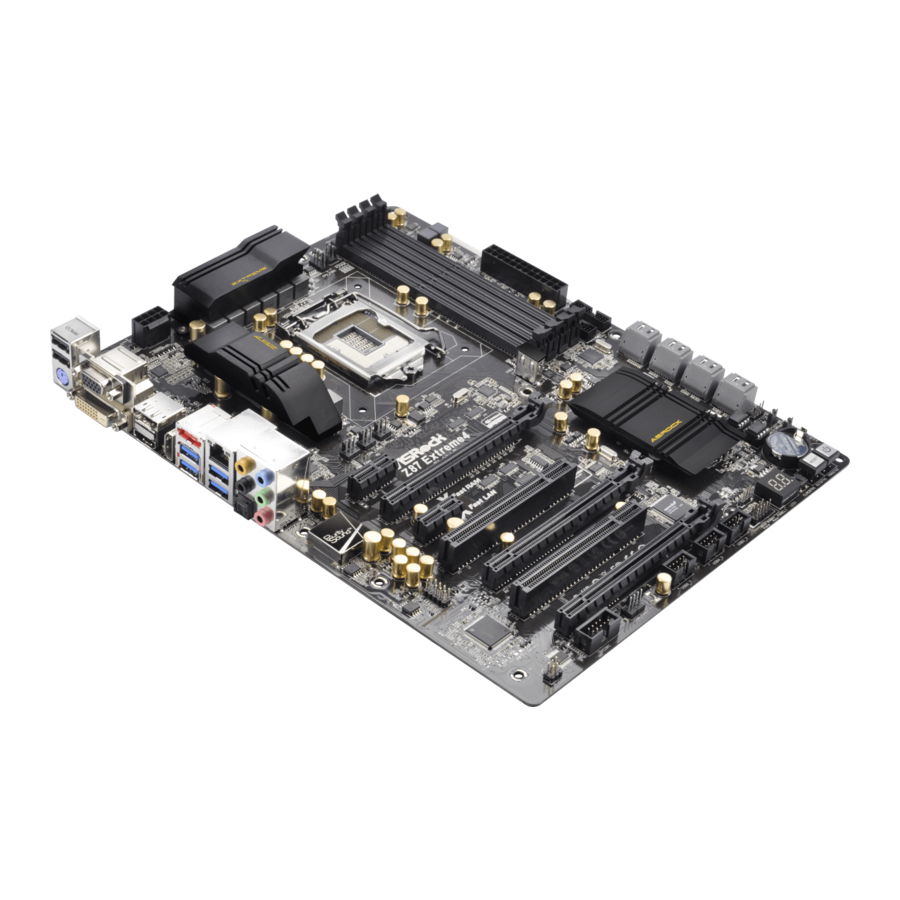
Seite 3: Motherboard-Layout
Z87 Extreme4 Motherboard Layout CPU_FAN2 CPU_FAN1 ATX12V1 HDMI_IN1 USB 3.0 T: USB0 B: USB1 USB 3.0 Top: T: USB2 RJ-45 B: USB3 PWR_FAN1 CHA_FAN3 CHA_FAN2 USB3_8 Z87 Extreme4 PCIE1 PCI Express 3.0 PCIE2 Purity Sound Fast RAM PCIE3 Fast LAN... - Seite 4 No. Description ATX 12V Power Connector (ATX12V1) Chassis Fan Connector (CHA_FAN2) CPU Fan Connector (CPU_FAN1) CPU Fan Connector (CPU_FAN2) 2 x 240-pin DDR3 DIMM Slots (DDR3_A1, DDR3_B1) 2 x 240-pin DDR3 DIMM Slots (DDR3_A2, DDR3_B2) ATX Power Connector (ATXPWR1) USB 3.0 Header (USB3_4_5) (ASMedia Hub) USB 3.0 Header (USB3_6_7) (ASMedia Hub) Vertical Type A USB 3.0 (USB3_12) SATA3 Connectors (SATA3_A0_A1)
- Seite 5 Z87 Extreme4 I/O Panel No. Description No. Description USB 2.0 Ports (USB01) Microphone (Pink) VGA Port Optical SPDIF Out Port Display Port USB 3.0 Ports (USB3_23) eSATA Connector*** USB 3.0 Ports (USB3_01) LAN RJ-45 Port* HDMI-In Port Central / Bass (Orange)
- Seite 6 * There are two LEDs on each LAN port. Please refer to the table below for the LAN port LED indications. ACT/LINK LED SPEED LED LAN Port Activity / Link LED Speed LED Status Description Status Description No Link 10Mbps connection Blinking Data Activity Orange...
-
Seite 7: Package Contents
If you require technical support related to this mother- board, please visit our website for specific information about the model you are using. You may find the latest VGA cards and CPU support list on ASRock’s website as well. ASRock website http://www.asrock.com. - Seite 8 • 12 Power Phase Design • Supports Intel ® Turbo Boost 2.0 Technology • Supports Intel ® K-Series unlocked CPU • Supports ASRock BCLK Full-range Overclocking • Intel ® Chipset • Dual Channel DDR3 Memory Technology Memory • 4 x DDR3 DIMM slots • Supports DDR3 2933+(OC)/2800(OC)/2400(OC)/2133(OC)/...
- Seite 9 Z87 Extreme4 • Intel® HD Graphics Built-in Visuals and the VGA outputs can Graphics be supported only with processors which are GPU integrated. • Supports Intel® HD Graphics Built-in Visuals : Intel® Quick Sync Video with AVC, MVC (S3D) and MPEG-2 Full HW Encode1, Intel®...
-
Seite 10: Rear Panel
• Gigabit LAN 10/100/1000 Mb/s • Giga PHY Intel® I217V • Supports Intel® Remote Wake Technology • Supports Wake-On-LAN • Supports Energy Efficient Ethernet 802.3az • Supports PXE • 1 x PS/2 Keyboard/Mouse Port Rear Panel • 1 x D-Sub Port • 1 x DVI-D Port • 1 x HDMI-Out Port • 1 x HDMI-In Port... -
Seite 11: Hardware Monitor
Z87 Extreme4 • 1 x IR header Connector • 1 x COM port header • 1 x Power LED header • 2 x CPU Fan connectors (1 x 4-pin, 1 x 3-pin) • 3 x Chassis Fan connectors (1 x 4-pin, 2 x 3-pin) • 1 x Power Fan connector (3-pin) - Seite 12 Due to limitation, the actual memory size may be less than 4GB for the reservation for sys- tem usage under Windows® 32-bit operating systems. Windows® 64-bit operating systems do not have such limitations. You can use ASRock XFast RAM to utilize the memory that Windows® cannot use.
-
Seite 13: Unique Features
LED, FAN-Tastic Tuning, OC Tweaker and a whole lot more. ASRock Instant Flash ASRock Instant Flash is a BIOS flash utility embedded in Flash ROM. This conve- nient BIOS update tool allows you to update the system BIOS in a few clicks without preparing an additional floppy diskette or other complicated flash utility. - Seite 14 And it also boosts the speed of Adobe Photoshop 5 times faster. Another advantage of ASRock XFast RAM is that it reduces the frequency of accessing your SSDs or HDDs in order to extend their lifespan.
- Seite 15 Windows® 8 brings the ultimate boot up experience. The lightning boot up speed makes it hard to access the UEFI setup. ASRock Restart to UEFI allows users to enter the UEFI automatically when turning on the PC. By enabling this function, the PC will enter the UEFI directly after you restart.
- Seite 16 ASRock Distortion-Free Slot ASRock's new pin design for the memory slots and PCIe slots may appear to be the same as former designs, but actually effectively reduces distortion and promotes performance, because we strive for perfection even in the most trivial details.
- Seite 17 Chapter 2 Installation This is an ATX form factor motherboard. Before you install the motherboard, study the configuration of your chassis to ensure that the motherboard fits into it. Pre-installation Precautions Take note of the following precautions before you install motherboard components or change any motherboard settings.
-
Seite 18: Installing The Cpu
2.1 Installing the CPU 1. Before you insert the 1150-Pin CPU into the socket, please check if the PnP cap is on the socket, if the CPU surface is unclean, or if there are any bent pins in the socket. Do not force to insert the CPU into the socket if above situation is found. - Seite 19 Z87 Extreme4...
- Seite 20 Please save and replace the cover if the processor is removed. The cover must be placed if you wish to return the motherboard for after service.
- Seite 21 Z87 Extreme4 2.2 Installing the CPU Fan and Heatsink...
- Seite 22 2.3 Installing Memory Modules (DIMM) This motherboard provides four 240-pin DDR3 (Double Data Rate 3) DIMM slots, and supports Dual Channel Memory Technology. 1. For dual channel configuration, you always need to install identical (the same brand, speed, size and chip-type) DDR3 DIMM pairs. 2.
- Seite 23 Z87 Extreme4...
- Seite 24 2.4 Expansion Slots (PCI and PCI Express Slots) There are 2 PCI slots and 5 PCI Express slots on the motherboard. Before installing an expansion card, please make sure that the power supply is switched off or the power cord is unplugged. Please read the documentation of the expansion card and make necessary hardware settings for the card before you start the installation.
- Seite 25 Z87 Extreme4 2.5 Jumpers Setup The illustration shows how jumpers are setup. When the jumper cap is placed on the pins, the jumper is “Short”. If no jumper cap is placed on the pins, the jumper is “Open”. The illustration shows a 3-pin jumper whose pin1 and pin2 are “Short”...
- Seite 26 BIOS Selection Jumper (BIOS_SEL1) Default Backup BIOS (see p.1, No. 16) (Main BIOS) This motherboard has two BIOS onboard, a main BIOS (BIOS_A) and a backup BIOS (BIOS_B), which enhances protection for the safety and stability of your system. Normally, the system works on the main BIOS. However, if the main BIOS is corrupted or damaged, please use a jumper cap to short pin2 and pin3, then the backup BIOS will take over on the next system boot.
- Seite 27 Z87 Extreme4 2.6 Onboard Headers and Connectors Onboard headers and connectors are NOT jumpers. Do NOT place jumper caps over these headers and connectors. Placing jumper caps over the headers and connectors will cause permanent damage to the motherboard. System Panel Header...
- Seite 28 Power LED Header Please connect the chassis (3-pin PLED1) power LED to this header PLED- PLED+ PLED+ (see p.1, No. 21) to indicate the system’s power status. Serial ATA3 Connectors These eight SATA3 (SATA3_0_1: connectors support SATA see p.1, No. 12) data cables for internal (SATA3_2_3: storage devices with up...
- Seite 29 Z87 Extreme4 Front Panel Audio Header This header is for GN D OUT2_L (9-pin HD_AUDIO1) connecting audio devices J_SENSE PRESENCE# OUT2_R (see p.1, No. 29) MIC_RET to the front audio panel. MIC2_R OUT_RET MIC2_L 1. High Definition Audio supports Jack Sensing, but the panel wire on the chassis must sup- port HDA to function correctly.
- Seite 30 CPU Fan Connectors This motherboard pro- FAN_SPEED_CONTROL FAN_SPEED (4-pin CPU_FAN1) vides a 4-Pin CPU fan + 12V (see p.1, No. 3) (Quiet Fan) connector. GN D If you plan to connect a (3-pin CPU_FAN2) 3-Pin CPU fan, please FAN_SPEED + 12V (see p.1, No.
-
Seite 31: Smart Switches
Z87 Extreme4 2.7 Smart Switches The motherboard has three smart switches: Power Switch, Reset Switch and Clear CMOS Switch, allowing users to quickly turn on/off the system, reset the system or clear the CMOS values. Power Switch Power Switch allows users... -
Seite 32: Einleitung
1 Einleitung Vielen Dank, dass Sie sich für das Z87 Extreme4 von ASRock entschieden haben – ein zuverlässiges Motherboard, das konsequent unter der strengen Qualitätskontrolle von ASRock hergestellt wurde. Es liefert ausgezeichnete Leistung mit robustem Design, das ASRocks Streben nach Qualität und Beständigkeit erfüllt. -
Seite 33: Technische Daten
Z87 Extreme4 1.2 Technische Daten • ATX-Formfaktor Plattform • Premium Gold-Kondensatordesign (100 % in Japan gefertigt, hochqualitative leitfähige Polymer-Kondensatoren) • Unterstützt Intel® CoreTM i7 / i5 / i3 / Xeon® / Pentium® / Prozessor Celeron® der 4. Generation im LGA1150-Paket • Digipower-Design... - Seite 34 • Integrierte Intel® HD Graphics-Visualisierung und VGA- Grafikkarte Ausgänge können nur mit Prozessoren unterstützt werden, die GPU-integriert sind. • Unterstützt integrierte Intel® HD Graphics-Visualisierung: Intel® Quick Sync Video mit AVC, MVC (S3D) und MPEG- 2 Full HW Encode1, Intel® InTru 3D, Intel®...
-
Seite 35: Funktionen
Z87 Extreme4 • Gigabit LAN 10/100/1000 Mb/s • Giga PHY Intel® I217V • Unterstützt Intel® Remote Wake Technology • Unterstützt Wake-On-LAN • Unterstützt energieeffizientes Ethernet 802.3az • Unterstützt PXE • 1 x PS/2-Tastatur-/Mausanschluss Rückblende, • 1 x D-Sub-Port • 1 x DVI-D-Port • 1 x HDMI-Ausgang... -
Seite 36: Anschluss
• 1 x IR-Stiftleiste Anschluss • 1 x COM-Anschluss-Stiftleiste • 1 x Betrieb-LED-Stiftleiste • 2 x CPU-Lüfteranschlüsse (1 x 4-polig, 1 x 3-polig) • 3 x Gehäuselüfteranschlüsse (1 x 4-polig, 2 x 3-polig) • 1 x Netzteillüfteranschluss (3-polig) • 1 x 24-poliger ATX-Netzanschluss • 1 x 8-poliger 12-V-Netzanschluss • 1 x Audioanschluss an Frontblende • 3 x USB 2.0-Stiftleisten (unterstützt sechs USB 2.0-Ports) - Seite 37 Aufgrund von Beschränkungen kann die Größe des tatsächlich für die Systemnutzung reservierten Speichers unter Windows®-Betriebssystemen mit 32 Bit weniger als 4 GB betragen. Windows®-Betriebssysteme mit 64 Bit haben keine derartigen Beschränkungen. Mit ASRock XFast RAM können Sie den Speicher einsetzen, den Windows® nicht nutzen kann.
-
Seite 38: Jumpereinstellung
1.3 Jumpereinstellung Die Abbildung zeigt, wie die Jumper eingestellt werden. Wenn die Jumper-Kappe auf den Kontakten angebracht ist, ist der Jumper „kurzgeschlossen“. Wenn keine Jumper- Kappe auf den Kontakten angebracht ist, ist der Jumper „offen“. Die Abbildung zeigt einen 3-poligen Jumper, dessen Kontakt 1 und Kontakt 2 „kurzgeschlossen“ sind, wenn eine Jumper-Kappe auf diesen 2 Kontakten angebracht ist. -
Seite 39: Standard Ausfall-Bios (Haupt-Bios)
Z87 Extreme4 BIOS-Auswahl-Jumper (BIOS_SEL1) Standard Ausfall-BIOS (siehe S. 1, Nr. 16) (Haupt-BIOS) Dieses Motherboard verfügt über zwei integrierte BIOS, ein Haupt-BIOS (BIOS_ A) und ein Ausfall-BIOS (BIOS_B), die den Schutz in puncto Sicherheit und Stabilität Ihres Systems steigern. Normalerweise läuft das System über das Haupt- BIOS. -
Seite 40: Integrierte Stiftleisten Und Anschlüsse
1.4 Integrierte Stiftleisten und Anschlüsse Integrierte Stiftleisten und Anschlüsse sind KEINE Jumper. Bringen Sie KEINE Jumper-Kappen an diesen Stiftleisten und Anschlüssen an. Durch Anbringen von Jumper-Kappen an diesen Stiftleisten und Anschlüssen können Sie das Motherboard dauerhaft beschädigen. Systemblende-Stiftleiste Verbinden Sie PLED+ PLED- PWRBTN#... -
Seite 41: Serial-Ata-Iii-Anschlüsse
Z87 Extreme4 Betrieb-LED-Stiftleiste Bitte verbinden Sie (3-polig, PLED1) die Betrieb-LED des PLED- PLED+ PLED+ (siehe S. 1, Nr. 21) Gehäuses zur Anzeige des Systembetriebsstatus mit dieser Stiftleiste. Serial-ATA-III-Anschlüsse Diese acht SATA-III- Anschlüsse unterstützen (SATA3_0_1: SATA-Datenkabel für siehe S. 1, Nr. 12) interne Speichergeräte... - Seite 42 Audiostiftleiste Diese Stiftleiste dient GN D OUT2_L (Frontblende) dem Anschließen von J_SENSE PRESENCE# OUT2_R (9-polig, HD_AUDIO1) MIC_RET Audiogeräten an der MIC2_R OUT_RET MIC2_L (siehe S. 1, Nr. 29) Frontblende. 1. High Definition Audio unterstützt Anschlusserkennung, der Draht am Gehäuse muss dazu jedoch HDA unterstützt.
- Seite 43 Z87 Extreme4 CPU-Lüfteranschlüsse Dieses Motherboard bietet FAN_SPEED_CONTROL FAN_SPEED (4-polig, CPU_FAN1) einen 4-poligen CPU- + 12V (siehe S. 1, Nr. 3) Lüfteranschluss (lautloser GN D Lüfter). Falls Sie einen (3-polig, CPU_FAN2) 3-poligen CPU-Lüfter FAN_SPEED + 12V (siehe S. 1, Nr. 4) anschließen möchten,...
- Seite 44 1.5 Intelligente Schalter Das Motherboard hat drei intelligente Schalter: Ein-/Ausschalter, Reset-Schalter und CMOS-löschen-Schalter, wodurch Benutzer das System schnell ein-/abschalten, zurücksetzen bzw. die CMOS-Werte löschen können. Ein-/Ausschalter Mit dem Ein-/Ausschalter (PWRBTN) kann der Benutzer das (siehe S. 1, Nr. 18) System schnell ein-/ abschalten.
-
Seite 45: Contenu De L'emballage
à modification sans préavis. En cas de modifications du présent document, la version mise à jour sera disponible sur le site Internet ASRock sans notification préalable. Si vous avez besoin d’une assistance technique pour votre carte mère, veuillez visiter notre site Internet pour plus de détails sur le modèle que vous utilisez. - Seite 46 Spécifications • Facteur de forme ATX Plateforme • Condensateur de conception premium or (condensateurs haute qualité en polymère conducteur 100% fabriqués au Japon) • Prend en charge les processeurs de 4ème Génération Intel® Processeur CoreTM i7 / i5 / i3 / Xeon® / Pentium® / Celeron® en package LGA1150 • Conception Digi Power • Alimentation à...
- Seite 47 Z87 Extreme4 • La technologie Intel® HD Graphics Built-in Visuals et les sorties Graphiques VGA sont uniquement prises en charge par les processeurs intégrant un contrôleur graphique. • Prend en charge la technologie Intel® HD Graphics Built-in Visuals : Intel® Quick Sync Video with AVC, MVC (S3D) and MPEG-2 Full HW Encode1, Intel®...
- Seite 48 • Gigabit LAN 10/100/1000 Mb/s Réseau • Giga PHY Intel® I217V • Prend en charge la technologie Intel® Remote Wake • Prend en charge la fonction Wake-On-LAN • Prend en charge la fonction d’ é conomie d’ é nergie Ethernet 802.3az • Prend en charge PXE • 1 x port clavier/souris PS/2...
- Seite 49 Z87 Extreme4 • 1 x embase IR Connectique • 1 x embase pour port COM • 1 x embase LED d’alimentation • 2 x connecteurs pour ventilateur de processeur (1 x 4 broches, 1 x 3 broches) • 3 x connecteurs pour ventilateur de châssis (1 x 4 broches, 2 x 3 broches) • 1 x connecteur pour ventilateur d’alimentation (3 broches)
- Seite 50 Certifications • ErP/EuP Ready (alimentation ErP/EuP ready requise) * pour des informations détaillées de nos produits, veuillez visiter notre site : http://www.asrock.com Il est important de signaler que l'overcloking présente certains risques, incluant des modifications du BIOS, l’ a pplication d’une technologie d’ o verclocking déliée et l'utilisation d'outils d'overclocking développés par des tiers.
- Seite 51 Z87 Extreme4 1.3 Configuration des cavaliers (jumpers) L’illustration ci-dessous vous renseigne sur la configuration des cavaliers (jumpers). Lorsque le capuchon du cavalier est installé sur les broches, le cavalier est ‘court-circuité’ . Si le capuchon du cavalier n’ e st pas installé sur les broches, le cavalier est ‘ouvert’ .
- Seite 52 Sélection du cavalier du BIOS (BIOS_SEL1) Par défaut BIOS de secours (voir p.1, No. 16) (BIOS principal) Cette carte mère est dotée de deux BIOS – un BIOS principal (BIOS_A), et un BIOS de secours (BIOS_B) – ce qui permet d’ o ptimiser la protection du système pour des performances fiables et stables.
- Seite 53 Z87 Extreme4 1.4 Embases et connecteurs de la carte mère Les embases et connecteurs situés sur la carte NE SONT PAS des cavaliers. Ne placez JAMAIS de capuchons de cavaliers sur ces embases ou connecteurs. Placer un capuchon de cavalier sur ces embases ou connecteurs endommagera irrémédiablement votre carte mère.
- Seite 54 Embase LED Veuillez brancher le d’alimentation LED d’alimentation du PLED- PLED+ PLED+ (PLED1 à 3 broches) châssis sur cette embase (voir p.1, No. 21) pour indiquer l’ é tat d’alimentation du système. Connecteurs Serial ATA3 Ces huit connecteurs (SATA3_0_1: SATA3 sont compatibles voir p.1, No.
- Seite 55 Z87 Extreme4 Embase audio du panneau Cette embase sert au GN D OUT2_L frontal branchement des appareils J_SENSE PRESENCE# OUT2_R (HD_AUDIO1 à 9 MIC_RET audio au panneau audio MIC2_R OUT_RET MIC2_L broches) frontal. (voir p.1, No. 29) 1. L’ a udio haute définition prend en charge la technologie Jack Sensing (détection de la fiche), mais le panneau grillagé...
- Seite 56 Connecteurs du Cette carte mère est dotée FAN_SPEED_CONTROL FAN_SPEED d’un connecteur pour ventilateur du processeur + 12V ventilateur de processeur (CPU_FAN1 à 4 broches) GN D (Quiet Fan) à 4 broches. (voir p.1, No. 3) Si vous envisagez de FAN_SPEED connecter un ventilateur + 12V (CPU_FAN2 à...
- Seite 57 Z87 Extreme4 1.5 Boutons intelligents La carte mère est équipée de trois boutons intelligents : bouton de mise en marche, bouton de réinitialisation et bouton d’ e ffacement CMOS qui permettent aux utilisateurs d’allumer/éteindre le système, de réinitialiser le système ou d’ e ffacer les valeurs CMOS en toute simplicité.
-
Seite 58: Contenuto Della Confezione
Web di ASRock senza ulteriore preavviso. Per il supporto tecnico correlato a questa scheda madre, visitare il nostro sito Web per informazioni specifiche relative al modello attualmente in uso. - Seite 59 Z87 Extreme4 1.2 Specifiche • Fattore di forma ATX Piattaforma • Design condensatore Premium Gold (condensatori a conduttore in polimero di alta qualità realizzati al 100% in Giappone) • Supporta Intel® CoreTM i7 / i5 / i3 di 4^ generazione / Xeon® / Pentium®...
- Seite 60 • La videografica integrata della scheda video HD Intel® e le Grafica uscite VGA possono essere supportate soltanto con processori con GPU integrata. • Supporta la videografica integrata della scheda video HD Intel®: Intel® Quick Sync Video con AVC, MVC (S3D) e MPEG-2 Full HW Encode1, Intel®...
- Seite 61 Z87 Extreme4 • LAN Gigabit 10/100/1000 Mb/s • Giga PHY Intel® I217V • Supporta la tecnologia Intel® Remote Wake • Supporta Wake-On-LAN • Supporta Energy Efficient Ethernet 802.3az • Supporta PXE • 1 x porta tastiera/mouse PS/2 I/O pannello • 1 x porta D-Sub posteriore • 1 x porta DVI-D...
-
Seite 62: Caratteristiche
• 1 x header IR Connettore • 1 x header porta COM • 1 x header LED di alimentazione • 2 x connettori ventola CPU (1 x 4 pin, 1 x 3 pin) • 3 x connettori ventola chassis (1 x 4 pin, 2 x 3 pin) • 1 x connettore ventola alimentazione (3 pin) • 1 x connettore alimentazione ATX a 24 pin • 1 x connettore alimentazione da 12 V a 8 pin... - Seite 63 Certificazioni • ErP/EuP Ready (è necessaria alimentazione ErP/EuP ready) * Per informazioni dettagliate sul prodotto, visitare il nostro sito Web: http://www.asrock.com Prestare attenzione al potenziale rischio previsto nella pratica di overclocking, inclusa la regolazione delle impostazioni nel BIOS, l'applicazione di tecnologia di Untied Overclocking o l'utilizzo di strumenti di overclocking di terze parti.
- Seite 64 1.3 Impostazione jumper L'illustrazione mostra in che modo vengono impostati i jumper. Quando il cappuccio del jumper è posizionato sui pin, il jumper è "cortocircuitato". Se sui pin non è posizionato alcun cappuccio del jumper, il jumper è "aperto". L'illustrazione mostra un jumper a 3 pin i cui pin1 e pin2 sono "cortocircuitati"...
- Seite 65 Z87 Extreme4 Jumper di selezione BIOS (BIOS_SEL1) predefinito BIOS di backup (vedere pag. 1, n. 16) (Main BIOS) Questa scheda madre è dotata di due BIOS, un BIOS principale (BIOS_A) e un BIOS di backup (BIOS_B), che migliorano la protezione, la sicurezza e la stabilità del sistema.
- Seite 66 1.4 Header e connettori sulla scheda Gli header e i connettori sulla scheda NON sono jumper. NON posizionare cappucci del jumper su questi header e connettori. Il posizionamento di cappucci del jumper su header e connettori provocherà danni permanenti alla scheda madre. Header sul pannello del Collegare l'interruttore PLED+...
-
Seite 67: Inhaltsverzeichnis
Z87 Extreme4 Header LED di Collegare il LED di alimentazione alimentazione chassis a PLED- PLED+ PLED+ (PLED1 a 3 pin) questo header per indicare (vedere pag. 1, n. 21) lo stato di alimentazione del sistema. Connettori Serial ATA3 Questi otto connettori... - Seite 68 Header audio pannello Questo header serve a GN D OUT2_L anteriore collegare i dispositivi J_SENSE PRESENCE# OUT2_R (AUDIO1_HD a 9 pin) MIC_RET audio al pannello audio MIC2_R OUT_RET MIC2_L (vedere pag. 1, n. 29) anteriore. 1. L'audio ad alta definizione supporta le funzioni Jack sensing, ma il filo del pannello sullo chassis deve supportare HDA per funzionare correttamente.
- Seite 69 Z87 Extreme4 Connettori della ventola Questa scheda madre è FAN_SPEED_CONTROL FAN_SPEED della CPU dotata di un connettore + 12V (CPU_FAN1 a 4 pin) per la ventola della CPU GN D (vedere pag. 1, n. 3) (Ventola silenziosa) a 4 pin.
- Seite 70 1.5 Interruttori intuitivi La scheda madre è dotata di tre interruttori intuitivi: Interruttore d’alimentazione, interruttore di ripristino ed interruttore Clear CMOS, che consentono di accendere/ spegnere rapidamente il sistema, ripristinare il sistema o cancellare i valori CMOS. Interruttore L’interruttore d’alimentazione d’alimentazione consente (PWRBTN) di accendere/spegnere...
-
Seite 71: Contenido Del Paquete
Si esta documentación sufre alguna modificación, la versión actualizada estará disponible en el sitio web de ASRock sin previo aviso. Si necesita asistencia técnica relacionada con esta placa base, visite nuestro sitio web para obtener información específica sobre el modelo que esté... - Seite 72 1.2 Especificaciones • Factor de forma ATX Plataforma • Diseño de los Condensadores: Premium Gold (Condensadores de polímero conductor, de alta calidad, 100% fabricados en Japón) • Compatible con 4.ª Generación de Intel® CoreTM i7 / i5 / i3 / Xeon®...
- Seite 73 Z87 Extreme4 • La Tecnología visual integrada de gráficos HD de Intel® y las Gráficos salidas de VGA son compatibles únicamente con procesadores con GPU integrado. • Compatible con la Tecnología visual integrada de gráficos HD de Intel®: Intel® Quick Sync Video con AVC, MVC (S3D) y MPEG-2 Full HW Encode1, Intel®...
-
Seite 74: Panel Trasero
• LAN Gigabit 10/100/1000 Mb/s • Giga PHY Intel® I217V • Compatible con la Tecnología Remote Wake de Intel® • Compatible con Wake-On-LAN • Compatible con Ethernet de consumo eficiente de energía 802.3az • Compatible con PXE • 1 puerto de teclado/ratón PS/2 Panel trasero • 1 puerto D-Sub • 1 puerto DVI-D... -
Seite 75: Características
Z87 Extreme4 • 1 cabezal IR Conectores • 1 cabezal de puerto COM • 1 cabezal de indicador LED de alimentación • 2 conectores de ventilador de la CPU (1 de 4 pines y 1 de 3 pines) • 3 conectores de ventilador del chasis (1 de 4 pines y 2 de 3 pines) • 1 conector de ventilador de alimentación (de 3 pines) - Seite 76 ErP/EuP) * Para obtener más información acerca del producto, visite nuestro sitio web: http://www.asrock.com Tenga en cuenta que existen ciertos riesgos relacionados con el overclocking (sobreaceleración), incluyendo el ajuste de la configuración del BIOS, aplicando la Tecnología overcloking no vinculada o utilizando las herramientas de overclocking de tercera parte.
- Seite 77 Z87 Extreme4 1.3 Instalación de los puentes La instalación muestra cómo deben instalarse los puentes. Cuando la tapa de puente se coloca en los pines, el puente queda “Corto”. Si no coloca la tapa de puente en los pines, el puente queda “Abierto”. La ilustración muestra un puente de 3 pines cuyo pin 1 y pin 2 son “Cortos”...
- Seite 78 Puente de selección del BIOS (BIOS_SEL1) Predeterminado BIOS de copia de seguridad (consulte la pág.1, N.º 16) (BIOS Principal) Esta placa base contiene dos BIOS integrados, un BIOS principal (BIOS_A) y un BIOS de copia de seguridad (BIOS_B), que aumentan la protección para la seguridad y la estabilidad de su sistema.
- Seite 79 Z87 Extreme4 1.4 Conectores y cabezales incorporados Los cabezales y conectores incorporados NO son puentes. NO coloque tapas de puente sobre estos cabezales y conectores. Si coloca tapas de puente sobre los cabezales y conectores dañará de forma permanente la placa base.
-
Seite 80: (Usb3_8)
Cabezal de indicador LED Conecte el indicador LED de alimentación de alimentación del chasis PLED- PLED+ PLED+ (PLED1 de 3 pines) a este cabezal para indicar (consulte la pág.1, N.º 21) el estado de alimentación del sistema. Conectores Serie ATA3 Estos ocho conectores SATA3 son compatibles (SATA3_0_1:... - Seite 81 Z87 Extreme4 Cabezal de audio del panel Este cabezal se utiliza para GN D OUT2_L frontal conectar dispositivos de J_SENSE PRESENCE# OUT2_R (HD_AUDIO1 de 9 pines) MIC_RET audio al panel de audio MIC2_R OUT_RET MIC2_L (consulte la pág.1, N.º 29) frontal.
- Seite 82 Conectores del ventilador Esta placa base contiene FAN_SPEED_CONTROL FAN_SPEED de la CPU un conector de ventilador + 12V (CPU_FAN1 de 4 pines) (ventilador silencioso) de GN D (consulte la pág.1, N.º 3) CPU de 4 pines. Si tiene pensando conectar un FAN_SPEED + 12V (CPU_FAN2 de 3 pines)
- Seite 83 Z87 Extreme4 1.5 Interruptores inteligentes La placa base contiene tres interruptores inteligentes: Interruptor de alimentación, interruptor de reseteo e interruptor de borrado de CMOS; que permiten a los usuarios encender y apagar rápidamente el sistema, resetearlo o borrar los valores de CMOS.
-
Seite 84: Комплект Поставки
уведомления. При необходимости технической поддержки, связанной с материнской платой, посетите веб-сайт и найдите на нем информацию о модели используемой вами материнской платы. На веб-сайте ASRock также можно найти самый последний перечень поддерживаемых VGA-карт и ЦП. Веб-сайт ASRock http://www.asrock.com. 1.1 Комплект поставки... - Seite 85 Z87 Extreme4 1.2 Спецификация • Форм-фактор ATX Платформа • Конструкция Premium Gold Capacitor (с использованием высококачественных конденсаторов из проводящих полимеров производства Японии) • Поддержка процессоров 4-го поколения Intel® CoreTM i7 / ЦП i5 / i3 / Xeon® / Pentium® / Celeron® в исполнении LGA1150 • Digi Power Design...
- Seite 86 • Поддержка выходных сигналов Intel® HD Graphics Built- Графическая in Visuals и VGA возможна только при использовании система процессоров со встроенными графическими процессорами. • Поддержка встроенных технологий визуализации Intel® HD Graphics: Intel® Quick Sync Video с AVC, MVC (S3D) и MPEG-2 Full HW Encode1, Intel® InTru 3D, Intel®...
- Seite 87 Z87 Extreme4 • Gigabit LAN 10/100/1000 Мб/с ЛВС • Giga PHY Intel® I217V • Поддержка технологии Intel® Remote Wake Technology • Поддержка Wake-On-LAN • Поддержка Energy Efficient Ethernet 802.3az • Поддержка PXE • 1 x PS/2 для клавиатуры/мыши Порты ввода- • 1 x D-Sub...
- Seite 88 • 1 x колодка IR Разъемы • 1 x колодка СОМ-порта • 1 x колодка светодиодного индикатора питания • 2 x разъем для вентилятора ЦП (1 х 4-контактный, 1 х 3-контактный) • 3 x разъема для вентилятора корпуса (1 х 4-контактный, 2 х...
- Seite 89 вызванный разгоном процессора. В связи с ограничением при работе под 32-разрядной ОС Windows® фактический объем памяти может быть меньше 4 Гбайт. Для 64-разрядных ОС Windows® таких ограничений нет. Для использования той памяти, которую ОС Windows® не может использовать, используйте ASRock XFast RAM.
- Seite 90 1.3 Установка перемычек Установка перемычек показана на рисунке. При установке колпачковой перемычки на контакты перемычка «замкнута». Если колпачковая перемычка на контакты не установлена, перемычка «разомкнута». На рисунке показана 3-контактная перемычка с замкнутыми контактами 1 и 2 при установке на них колпачковой...
- Seite 91 Z87 Extreme4 Перемычка выбора BIOS (BIOS_SEL1) по умолчанию Резервная BIOS (См. стр. 1, № 16) (основная BIOS) Эта материнская плата снабжена двумя BIOS — основной BIOS (BIOS_A) и BIOS резервного копирования (BIOS_B), — что повышает уровень защиты и стабильности работы системы. Обычно система использует основную BIOS.
- Seite 92 1.4 Колодки и разъемы, расположенные на материнской плате Расположенные на материнской плате колодки и разъемы перемычками НЕ являются. НЕ устанавливайте на эти колодки и разъемы колпачковые перемычки. Установка колпачковых перемычек на эти колодки и разъемы может вызвать неустранимое повреждение материнской платы. PLED+ Подключите...
- Seite 93 Z87 Extreme4 Колодка светодиодного Подключите светодиодный индикатор PLED- индикатора питания PLED+ питания корпуса к PLED+ (3-контактная, PLED1) этой колодке, чтобы (См. стр. 1, № 21) обеспечить индикацию состояния питания системы. Разъемы Serial ATA3 Эти шесть восемь SATA3 предназначены для (SATA3_0_1: подключения...
- Seite 94 Аудиоколодка передней Эта колодка GN D OUT2_L панели предназначена J_SENSE (9-контактная, HD_ для подключения PRESENCE# OUT2_R MIC_RET MIC2_R AUDIO1) аудиоустройств к OUT_RET MIC2_L (См. стр. 1, № 29) передней аудиопанели. 1. Аудиосистема высокого разрешения поддерживает функцию распознавания разъема, но для е правильной работы необходимо, чтобы провод панели корпуса поддерживал передачу...
- Seite 95 Z87 Extreme4 Разъемы вентиляторов ЦП Эта материнская FAN_SPEED_CONTROL плата снабжена FAN_SPEED (4-контактный, CPU_ + 12V 4-контактным разъемом FAN1) GN D для малошумящего (См. стр. 1, № 3) вентилятора ЦП. Если вы собираетесь подключить (3-контактный, CPU_ 3-контактный FAN_SPEED вентилятор охлаждения + 12V FAN2) процессора, подключайте...
- Seite 96 1.5 Электронные кнопки Материнская плата снабжена тремя электронными кнопками: кнопка питания, кнопка перезагрузки и переключатель сброса настроек CMOS, предназначенными для быстрого включения/выключения системы, перезагрузки системы и обнуления значений CMOS. Кнопка питания Кнопка питания (PWRBTN) предназначена для (См. стр. 1, № 18) быстрого...
-
Seite 97: Conteúdo Da Embalagem
Z87 Extreme4 1 Introdução Obrigado por ter comprado a placa principal ASRock Z87 Extreme4, uma placa principal fiável produzida sob os rigorosos critérios de controlo de qualidade da ASRock. Esta placa principal oferece um excelente desempenho com um design robusto em conformidade com o compromisso da ASRock em fabricar produtos de qualidade e resistentes. -
Seite 98: Especificações
1.2 Especificações • Formato ATX Plataforma • Design de condensadores banhados a ouro de alta qualidade (Condensadores de polímeros condutores de alta qualidade 100% fabricados no Japão) • Suporta processadores Intel® CoreTM i7 / i5 / i3 / Xeon® / Pentium®... - Seite 99 Z87 Extreme4 • Os gráficos incorporados Intel® HD e as saídas VGA apenas Gráficos podem ser suportados com processadores com GPU integrada. • Suporta gráficos incorporados Intel® HD: Intel® Quick Sync Video com AVC, MVC (S3D) e MPEG-2 Full HW Encode1, Intel®...
- Seite 100 • LAN Gigabit a 10/100/1000 Mb/s • Giga PHY Intel® I217V • Suporta tecnologia Intel® Remote Wake • Suporta Wake-On-LAN • Suporta IEEE 802.3az • Suporta PXE • 1 x Porta PS/2 para teclado/rato E/S do painel • 1 x Porta D-Sub traseiro • 1 x Porta DVI-D • 1 x porta de saída HDMI...
- Seite 101 Z87 Extreme4 • 1 x Terminal IV Conector • 1 x Terminal de porta COM • 1 x Conector para LED de alimentação • 2 x Conectores da ventoinha da CPU (1 x 4 pinos, 1 x 3 pinos) • 2 x Conectores da ventoinha do chassis (1 x 4 pinos, 2 x 3 pinos) • 1 x Conector da ventoinha de alimentação (3 pinos)
- Seite 102 Devido às limitações, o tamanho real da memória de 4GB reservada para utilização em sistemas operativos Windows® 32-bits poderá ser inferior. Os sistemas operativos Windows® 64- bits não possuem essas limitações. Pode utilizar o ASRock XFast RAM para dar uso à memória que o Windows® não utiliza.
- Seite 103 Z87 Extreme4 1.3 Configuração dos jumpers A imagem abaixo ilustra como os jumpers são configurados. Quando a tampa do jumper é colocada nos pinos, o jumper é "Curto". Se não for colocada uma tampa de jumper nos pinos, o jumper é "Aberto". A imagem ilustra um jumper de 3 pinos cujos pino1 e pino2 estão "Curtos"...
- Seite 104 Jumper de selecção da BIOS (BIOS_SEL1) Predefinição BIOS de reserva (consultar p.1, N.º 16) (BIOS principal) Esta placa principal possui duas BIOS integradas, uma BIOS principal (BIOS_A) e uma BIOS de reserva (BIOS_B), que aumenta a protecção, segurança e estabilidade do seu sistema.
- Seite 105 Z87 Extreme4 1.4 Terminais e conectores integrados Os terminais e conectores integrados NÃO são jumpers. NÃO coloque tampas de jumpers sobre estes terminais e conectores. Colocar tampas de jumpers sobre os terminais e conectores irá causar danos permanentes à placa principal.
- Seite 106 Conector do LED de Ligue o LED de alimentação do chassis a alimentação PLED- PLED+ este terminal para indicar PLED+ (PLED1 de 3 pinos) o estado de alimentação do (consultar p.1, N.º 21) sistema. Conectores ATA3 de série Estes oito conectores SATA3 suportam (SATA3_0_1: cabos de dados SATA...
- Seite 107 Z87 Extreme4 Terminal de áudio do Este terminal destina-se GN D OUT2_L painel frontal à ligação de dispositivos J_SENSE PRESENCE# OUT2_R (HD_AUDIO1 de 9 pinos) MIC_RET áudio ao painel de áudio MIC2_R OUT_RET MIC2_L (consultar p.1, N.º 29) frontal. 1. O Áudio de alta definição suporta Detecção de ficha, mas o cabo de painel no chassis deverá...
- Seite 108 Conectores da ventoinha Esta placa principal inclui FAN_SPEED_CONTROL FAN_SPEED da CPU um conector de ventoinha + 12V (CPU_FAN1 de 4 pinos) de CPU (Ventoinha GN D (consultar p.1, N.º 3) silenciosa) de 4 pinos. Se pretender ligar uma FAN_SPEED + 12V (CPU_FAN2 de 3 pinos) ventoinha de CPU de 3 (consultar p.1, N.º...
- Seite 109 Z87 Extreme4 1.5 Interruptores inteligentes A placa principal tem três interruptores inteligentes: Interruptor de Alimentação, Interruptor de Reposição e Interruptor para Limpar o CMOS, que permitem aos utilizadores ligar/desligar ou repor o sistema e limpar os valores CMOS rapidamente. Interruptor de alimentação...
-
Seite 110: Ambalaj İçeriği
Bu dokümantasyon üzerinde herhangi bir değişiklik yapılması halinde, güncellenmiş sürüm, herhangi bir bildirim yapılmaksızın ASRock'ın web sitesinde yer alacaktır.. Bu anakart ile ilgili olarak teknik destek almak istiyorsanız, lütfen kullandığınız model hakkında özel bilgiler için web sitemizi ziyaret edin. - Seite 111 Z87 Extreme4 1.2 Özellikler • ATX Form Faktörü Platform • Premium Gold Sığa tasarımı (%100 Japon-malı kaliteli İletken Polimer Sığalar) • 4ncü Nesil Intel® CoreTM i7 / i5 / i3 / Xeon® / Pentium® / Celeron®, LGA1150 Paketinde desteklemektedir • Dijital Güç Tasarımı...
- Seite 112 • Intel® HD Graphics Dahili Görselleri ile VGA çıktıları, yalnızca Grafikler GPU entegre edilmiş işlemciler ile desteklenir. • Intel® HD Graphics Dahili Görsellerini destekler : AVC, MVC (S3D) ve MPEG-2 Full HW Encode1, Intel® InTru 3D, Intel® Net Video HD Teknolojisi, Intel® Insider , Intel®...
- Seite 113 Z87 Extreme4 • Gigabit LAN 10/100/1000 Mb/s • Giga PHY Intel® I217V • Intel® Uzaktan Uyandırma Teknolojisi • LAN Açılışını Destekler • Enerji Verimliliğine Sahip Ethernet 802.3az işlevini destekler • PXE özelliğini destekler • 1 x PS/2 Klavye/Fare Bağlantı Noktası...
- Seite 114 • 1 x IR bağlantısı Bağlayıcı • 1 x COM Bağlantı noktası bağlantısı • 1 x Güç LED bağlantısı • 2 x CPU Fan bağlayıcıları (1 x 4-pin, 1 x 3-pin) • 3 x Kasa Fanı konektörü (1 x 4-pin, 2 x 3-pin) • 1 x Güç...
- Seite 115 • ErP/EuP için hazır (ErP/EuP için hazır güç beslemesi gereklidir) * Detaylı ürün bilgisi için, lütfen web sitemizi ziyaret edin: http://www.asrock.com Lütfen, BIOS ayarlarını düzenleme, Bağımsız Hız Aşırtma Teknolojinin uygulanması ya da üçüncü kişilerin hız aşırtma araçlarının kullanılması da dahil olmak üzere tüm hız aşırtma işlemlerinin belirli bir risk taşıdığını...
- Seite 116 1.3 Bağlantı Teli Kurulumu Çizim, bağlantı tellerinin kurulumunu göstermektedir. Tel kapağı, pimlerin üzerine yerleştirildiğinde, tel "Kısa" olur. Pimlerin üzerinde tel kapağı bulunmadığında, tel "Kısa" olur. Çizim, pin1 ve pin2 alanları "Kısa" olan ve bu iki pim üzerinde bir bağlantı teli kapağı bulunan 3-pin bağlantı telini göstermektedir. CMOS'u Temizle Bağlantı...
- Seite 117 Z87 Extreme4 BIOS Seçme Bağlama Teli (BIOS_SEL1) Varsayılan Yedek BIOS (bkz. sf.1, No. 16) (Ana BIOS) Bu anakartta sisteminizin güvenliği ve kararlılığı için korumayı artıran ana BIOS (BIOS_A) ve yedek BIOS (BIOS_B) olmak üzere iki adet BIOS vardır. Normalde sistem ana BIOS'ta çalışır. Ancak ana BIOS bozulur veya hasar görürse, lütfen pin2 ve pin3'ü...
- Seite 118 1.4 Ekli Bağlantılar ve Bağlayıcılar Ekli bağlantılar ve bağlayıcılar bağlantı teli değildir. Bağlantı teli kapaklarını bu bağlantı ve bağlayıcılar üzerine yerleştirmeyin. Bağlantı teli kapaklarının bağlantılar ile bağlayıcılar üzerine yerleştirilmesi, anakarta kalıcı hasar verebilir. Sistem Paneli Bağlantısı Güç anahtarını bağlayın, PLED+ PLED- PWRBTN# (9-pin PANEL1)
- Seite 119 Z87 Extreme4 Güç LED Bağlantısı Sistemin güç durumunun (3-pin PLED1) belirtilmesi için lütfen PLED- PLED+ PLED+ (bkz. sf.1, No. 21) güç LED'ini bu bağlantıya takın. Seri ATA3 Bağlayıcıları Bu sekiz SATA3 (SATA3_0_1: bağlayıcısı, veri aktarım bkz. sf.1, No. 12) hızı 6,0 Gb/sn'ye kadar...
- Seite 120 Ön Panel Ses Bağlantısı Bu bağlantı, ses aygıtlarının GN D OUT2_L (9-pin HD_AUDIO1) ön ses paneline bağlanması J_SENSE PRESENCE# OUT2_R (bkz. sf.1, No. 29) MIC_RET içindir. MIC2_R OUT_RET MIC2_L 1. Yüksek Tanımlı Ses, Jak Algılama özelliğini destekler, ancak bu işlevin düzgün çalışabilmesi için kasa üzerindeki panel kablosunun HDA işlevini desteklemesi gerekmektedir.
- Seite 121 Z87 Extreme4 CPU Fan Bağlayıcıları Bu anakart, 4-Pin CPU FAN_SPEED_CONTROL FAN_SPEED (4-pin CPU_FAN1) fan (Sessiz Fan) bağlayıcısı + 12V (bkz sf.1, No. 3) sağlamaktadır. 3-Pin CPU GN D fan bağlamak istiyorsanız, (3-pin CPU_FAN2) lütfen Pin 1-3'ü kullanın. FAN_SPEED + 12V (bkz sf.1, No.
- Seite 122 1.5 Akıllı Anahtar Anakartta üç adet akıllı düğme bulunur: Güç Düğmesi, Sıfırlama Düğmesi ve CMOS Temizleme Düğmesi kullanıcıların sistemi hızlı bir şekilde açıp kapatmalarını, sistemi sıfırlamalarını ve CMOS değerlerini temizlemelerini sağlar. Güç Düğmesi Güç Düğmesi, (PWRBTN) kullanıcıların sistemi (bkz. sf.1, No. 18) hızlı...
- Seite 123 마더보드 규격과 BIOS 소프트웨어를 업데이트할 수도 있기 때문에 , 이 문서의 내용은 예고 없이 변경될 수 있습니다 . 이 설명서가 변경될 경우 , 업데이트된 버전은 ASRock 의 웹사이트에서 추가 통지 없이 제공됩니다 . 이 마더보드와 관련하여 기술적 지원이 필요한 경우 , 당사의 웹사이트를 방문하여 사용 중인 모델에 대한 구체적...
- Seite 124 1.2 규격 • ATX 폼 팩터 플랫폼 • 프리미엄 골드 콘덴서 구조 (100% 일본산 고품질 전도성 폴리머 콘덴서 ) • LGA1150 패키지로 제공되는 4 세대 Intel® CoreTM i7 / i5 / i3 / Xeon® / Pentium® / Celeron® 지원 • Digi 전원 구조 • 12 개...
- Seite 125 Z87 Extreme4 • Intel® HD 그래픽스 빌트 - 인 비주얼과 VGA 출력은 GPU 그래픽 통합 프로세서로만 지원할 수 있습니다 . • Intel® HD 그래픽스 빌트 - 인 비주얼 지원 : AVC, MVC (S3D) 및 MPEG-2 풀 HW Encode1 지원 Intel® Quick Sync Video, 3D, Intel®...
- Seite 126 • Gigabit LAN 10/100/1000 Mb/s • Giga PHY Intel® I217V • Intel® 리모트 웨이크 기술 지원 • Wake-On-LAN 지원 • 절전형 이더넷 802.3az 지원 • PXE 지원 • PS 1 개 / 키보드 / 마우스 포트 2 개 후면 패널 I/O • D-Sub 포트...
- Seite 127 Z87 Extreme4 • IR 헤더 1 개 커넥터 • COM 포트 헤더 1 개 • 전원 LED 헤더 1 개 • CPU 팬 커넥터 2 개 (1 x 4 핀 , 1 x 3 핀 ) • 섀시 팬 커넥터 3 개 (1 x 4 핀 , 2 x 3 핀 ) • 전원...
- Seite 128 제한 때문에 실제 메모리 크기는 Windows® 32 비트 운영체제 하의 시스템 사용을 위한 예비 메모리용 4GB 보다 더 적을 수 있습니다 . Windows® 64 비트 운영체제에는 그러한 제한이 없습니다 . ASRock XFast RAM 을 사용하여 Windows® 가 사용할 수 없는 메모리를 이용할 수 있습니다 .
- Seite 129 Z87 Extreme4 1.3 점퍼 설정 그림은 점퍼를 어떻게 설정하는지 보여줍니다 . 점퍼 캡을 핀에 씌우면 점퍼가 “단락”됩니다 . 점퍼 캡을 핀에 씌우지 않으면 점퍼가 “단선”됩니다 . 그림 은 3 핀 점퍼를 보여주며 핀 1 과 핀 2 는 점퍼 캡을 씌울 때 “단락”됩니다 .
- Seite 130 BIOS 선택 점퍼 (BIOS_SEL1) 기본값 백업 BIOS (1 페이지 , 16 번 항목 참조 ) ( 메인 BIOS) 이 마더보드는 두 개의 BIOS, 즉 메인 BIOS (BIOS_A) 와 백업 BIOS (BIOS_B) 를 탑재하여 시스템의 안전 및 안정성에 대한 보호를 더욱 강화했습니다 . 평소에 시스템은...
- Seite 131 Z87 Extreme4 1.4 온보드 헤더 및 커넥터 온보드 헤더와 커넥터는 점퍼가 아닙니다 . 점퍼 캡을 온보드 헤더와 커넥터에 씌우지 마십시오 . 점퍼 캡을 온보드 헤더와 커넥터에 씌우면 마더보드가 영구적으로 손상됩 니다 . 시스템 패널 헤더 섀시의 전원 스위치 , PLED+...
- Seite 132 전원 LED 헤더 시스템 전원 상태를 나 (3 핀 PLED1) 타내려면 섀시 전원 PLED- PLED+ PLED+ (1 페이지 , 21 번 항목 참조 ) LED 를 이 헤더에 연결 하십시오 . 시리얼 ATA3 커넥터 이들 8 개의 SATA3 커 넥터는 최대 6.0 Gb/s (SATA3_0_1: 1 페이지...
- Seite 133 Z87 Extreme4 전면 패널 오디오 헤더 이 헤더는 오디오 장치 GN D OUT2_L (9 핀 HD_AUDIO1) 를 전면 오디오 패널에 J_SENSE PRESENCE# OUT2_R (1 페이지 , 29 번 항목 참조 ) MIC_RET 연결하는 데 사용됩니 MIC2_R OUT_RET MIC2_L 다 .
- Seite 134 CPU 팬 커넥터 이 마더보드에는 4 핀 FAN_SPEED_CONTROL FAN_SPEED (4 핀 CPU_FAN1) CPU 팬 ( 저소음 팬 ) + 12V (1 페이지 , 3 번 항목 참조 ) 커넥터가 탑재되어 GN D 있습니다 . 3 핀 CPU (3 핀 CPU_FAN2) 팬을...
- Seite 135 Z87 Extreme4 1.5 스마트 스위치 마더보드에는 스마트 스위치 세 개가 탑재되어 있습니다 : 전원 스위치 , 리셋 스 위치 및 CMOS 지우기 스위치 . 이들 스위치는 사용자가 시스템을 빨리 켜거나 끄고 , 시스템을 리셋하거나 CMOS 값을 지우게 할 수 있습니다 .
- Seite 136 1 はじめに ASRock Z87 Extreme4 マザーボードをお買い上げいただきまして誠にありがとうご ざいます。 ASRock Z87 Extreme4 マザーボードは、 ASRock の一貫した厳格な品質 管理の下で製造された信頼性の高いマザーボードです。 アスロックの品質と耐久 性の取り組みに準拠した堅牢な設計を持つ、 優れたパフォーマンスを提供します。 マザーボードの仕様と BIOS ソフトウェアは更新されるこ とがあるため、 このマニュアル の内容は予告なしに変更するこ とがあります。 このマニュアルの内容に変更があった場 合には、 更新されたバージョンは、 予告なく アスロックのウェブサイ トから入手できるよう になります。 このマザーボードに関する技術的なサポートが必要な場合には、 ご使用の モデルについての詳細情報を、 当社のウェブサイ トで参照く ださい。 アスロックのウェブ サイ トでは、 最新の VGA カードおよび CPU サポート一覧もご覧になれます。 アスロック...
- Seite 137 Z87 Extreme4 1.2 仕様 • ATX フォームファクター プラッ トフォー • プレミアムゴールドコンデンサー設計 (100% 日本製の高品 ム 質導電性高分子コンデンサー) • LGA1150 パッケージでは第 4 世代の Intel® CoreTM i7 / i5 / i3 / Xeon® / Pentium® / Celeron® をサポート • デジタル電源設計 • 12 電源フェーズ設計 ターボブースト 2.0 テク ノロジーをサポート...
- Seite 138 • Intel®HD グラフィ ックス内蔵ビジュアルおよび VGA 出力は、 グラフ ィ ックス GPU に統合されたプロセッサーのみでサポートされます。 • Intel®HD グラフィ ックス内蔵ビジュアルをサポート : AVC、 MVC (S3D)、 MPEG-2 フル HW エンコード 1 の Intel® Quick 3D、 Intel® ク リアビデオ HD テク Sync Video、 Intel® InTru ノロジー、 Intel® インサイダー 、...
- Seite 139 Z87 Extreme4 • ギガビッ ト LAN 10/100/1000 Mb/ 秒 • ギガ PHY Intel® I217V • Intel® リモートウェイクテク ノロジーをサポート • ウェイクオンランをサポート • エネルギー効率のよいイーサネッ ト 802.3az をサポート • PXE をサポート • 1 x PS/2 キーボード / マウスポート リアパネル I/O • 1 x D-Sub ポート...
- Seite 140 • 1 x IR ヘッダー コネクター • 1 x COM ポートヘッダー • 1 x 電源 LED ヘッダー • 2 x CPU ファインコネクター (1 x 4 ピン、 1 x 3 ピン) • 3 x シャーシファンコネクター (1 x 4 ピン、 2 x 3 ピン) • 1 x 電源ファンコネクター...
- Seite 141 • Microsoft® Windows® 8 / 8 64 ビッ ト / 7 / 7 64 ビッ ト準拠 認証 • FCC、 CE、 WHQL • ErP/EuP Ready ( ErP/EuP ready 電源が必要です) * 商品詳細については、 当社ウェブサイ トをご覧く ださい。 http://www.asrock.com BIOS 設定の調整、 アンタイ ドオーバークロックテク ノロジーの適用、 サードパーティのオー バークロックツールの使用などを含む、 オーバークロックには、 一定のリスクを伴います のでご注意く ださい。 オーバークロックするとシステムが不安定になったり、 システムの...
- Seite 142 1.3 ジャンパー設定 このイラストは、 ジャンパーの設定方法を示しています。 ジャンパーキャップがピ ンに被さっていると、 ジャンパーは 「ショート」 です。 ジャンパーキャップがピンに被 さっていない場合には、 ジャンパーは 「オープン」 です。 この図は 3ピンのジャンパー を表し、 ジャンパーキャップがピン 1 とピン 2 に被さっているとき、 これらのピンは 「ショート」 です。 CMOS クリアジャンパー (CLRCMOS1) デフォルト CMOS のク リア (p.1、 No. 17 参照) CLRCMOS1 は、 CMOS のデータをクリアするこ とができます。 ク リアして、 デフォ ルト設定にシステムパラメーターをリセッ...
- Seite 143 Z87 Extreme4 BIOS 選択ジャンパー (BIOS_SEL1) デフォルト バックアップ BIOS (p.1、 No. 16 参照) (メイン BIOS) このマザーボードは、 メイン BIOS ( BIOS_A) とバックアップ BIOS ( BIOS_B) の 2 つの BIOS がオンボードにあり、 システムの安全性と安定性のための保護を強化 しています。 通常、 システムはメイン BIOS 上で動作します。 メイン BIOS が壊れ たり、 損傷した場合には、 ジャンパーキャップを使用してピン 2 とピン 3 をショー...
- Seite 144 1.4 オンボードのヘッダーとコネクター オンボードヘッダーとコネクターはジャンパーではありません。 これらヘッダーとコネク ターにはジャンパーキャップを被せないでく ださい。 ヘッダーおよびコネクターにジャン パーキャップを被せると、 マザーボードに永久損傷が起こるこ とがあります。 システムパネルヘッダー 電源スイッチを接続し、 PLED+ PLED- (9 ピンパネル 1) スイッチをリセッ トし、 下 PWRBTN# (p.1、 No. 22 参照) 記のピン割り当てに従っ て、 シャーシのシステムス RESET# テータス表示ランプをこ HDLED- のヘッダーにセッ トしま HDLED+ す。 ケーブルを接続する ときには、 ピンの+と−に 気をつけてく ださい。 PWRBTN (電源スイッチ)...
- Seite 145 Z87 Extreme4 電源 LED ヘッダー システムの電源ステー (3 ピン PLED1) タスを表示するために、 PLED- PLED+ (p.1、 No. 21 参照) PLED+ シャーシ電源 LED をこの ヘッダーに接続してく だ さい。 シリアル ATA3 コネクタ これら 8 つの SATA3 コネ ー クタは、 最高 6.0 Gb/s の データ転送速度で内部 (SATA3_0_1: p.1、 No. 12) ( SATA3_2_3 :...
- Seite 146 フロントパネルオーディ このヘッダーは、 フロント GN D OUT2_L オヘッダー オーディオパネルにオー J_SENSE PRESENCE# OUT2_R (9 ピン HD_AUDIO1) ディオデバイスを接続す MIC_RET MIC2_R OUT_RET MIC2_L (p.1、 No. 29 参照) るためのものです。 1. ハイディフィニションオーディオはジャックセンシングをサポートしていますが、 正しく 機能するためには、 シャーシのパネルワイヤーが HDA をサポートしているこ とが必要 です。 お使いのシステムを取り付けるには、 当社のマニュアルおよびシャーシのマニュ アルの指示に従ってく ださい。 2. AC 97 オーディオパネルを使用する場合には、 次のステップで、 前面パネルオーディオ ヘッダーに取り付けてく...
- Seite 147 Z87 Extreme4 CPU ファンコネクター このマザーボードは 4 ピ FAN_SPEED_CONTROL (4 ピン CPU_FAN1) ン CPUファン (静音ファン) FAN_SPEED + 12V (p.1、 No. 3 参照) コネクターを提供します。 GN D 3 ピンの CPU ファンを接 (3 ピン CPU_FAN2) 続する場合には、 ピン 1-3 FAN_SPEED + 12V (p.1、 No. 4 参照)...
- Seite 148 1.5 スマートスイッチ マザーボードには 3 つのスマートスイッチが装備されています。 電源スイッチ、 リ セッ トスイッチ、 および、 クリア CMOS スイッチで、 システムを素早く オン / オフにし たり、 システムをリセッ トしたり、 CMOS 値をク リアできます。 電源スイッチ 電源スイッチで、 システム (PWRBTN) を素早く オン / オフにで (p.1、 No. 18 参照) きます。 リセッ トスイッチ リセッ トスイッチで、 シス (RSTBTN)...
- Seite 149 Z87 Extreme4 1 简介 感谢您购买 ASRock Z87 Extreme4 主板,这是按照 ASRock 一贯严格质量控制标 准生产的性能可靠的主板。它提供符合 ASRock 质量和耐久性承诺的精良设计 和卓越性能。 由于主板规格和 BIOS 软件可能已更新,因此,本文档的内容可能会随时更改,恕不 另行通知。如果本文档有任何修改,则更新的版本将发布在 ASRock 网站上,我们不 会另外进行通知。如果您需要与此主板相关的技术支持,请访问我们的网站以具体了 解所用型号的信息。您也可以在 ASRock 网站上找到最新 VGA 卡和 CPU 支持列表。 ASRock 网站 http://www.asrock.com。 1.1 包装清单 • ASRock Z87 Extreme4 主板(ATX 规格尺寸)...
- Seite 150 1.2 规格 • ATX 规格尺寸 平台 • 优质亮金电容器设计(100% 日本造高品质导电性高分子 电容器) • 支持 LGA1150 封装第 4 代 Intel® CoreTM i7 / i5 / i3 / Xeon® / Pentium® / Celeron® • Digi Power(帝捷)设计 • 12 电源相设计 • 支持 Intel ® Turbo Boost 2.0 技术 • 支持...
- Seite 151 Z87 Extreme4 • 只有 GPU 集成的处理器才支持 Intel® HD Graphics 内置视 图形 效和 VGA 输出。 • 支持 Intel® HD Graphics 内置视效 : Intel® 快速同步视频,采 用 AVC、MVC (S3D) 和 MPEG-2 Full HW Encode1、Intel® 3D、Intel® Clear Video HD 技术、Intel® Insider 、 InTru Intel® HD Graphics 4400/4600 • Pixel Shader 5.0、DirectX 11.1...
- Seite 152 • 1 x PS/2 键盘 / 鼠标端口 后面板 I/O • 1 x D-Sub 端口 • 1 x DVI-D 端口 • 1 x HDMI 输出端口 • 1 x HDMI 输入端口 • 1 x DisplayPort • 1 x 光学 SPDIF 输出端口 • 1 x eSATA 接口 • 2 x USB 2.0 端口...
- Seite 153 Z87 Extreme4 • 1 x IR 接脚 接口 • 1 x COM 端口接脚 • 1 x 电源 LED 接脚 • 2 x CPU 风扇接口 (1 x 4 针 , 1 x 3 针 ) • 3 x 机箱风扇接口 (1 x 4 针 , 2 x 3 针 ) • 1 x 电源风扇接口...
- Seite 154 • Microsoft® Windows® 8 / 8 64-bit / 7 / 7 64-bit 兼容 操作系统 • FCC、CE、WHQL 认证 • ErP/EuP 支持(需要支持 ErP/EuP 的电源) * 有关详细产品信息,请访问我们的网站: http://www.asrock.com 须认识到超频会有一定风险,包括调整 BIOS 设置,应用“自由超频技术”,或使用 第三方超频工具。超频可能会影响到系统的稳定性,甚至对系统的组件和设备造成损 坏。执行这项工作您应自担风险和自己承担费用。我们对由于超频而造成的损坏概不 负责。 由于限制原因,实际内存容量可能会小于 4GB,以保留给 Windows® 32-bit 操作系统 下的系统使用。Windows® 64-bit 操作系统没有此类限制。您可以使用 ASRock XFast RAM 来利用 Windows® 不能使用的内存。...
- Seite 155 Z87 Extreme4 1.3 跳线设置 此图显示如何设置跳线。将跳线帽装到这些针脚上时,跳线 “短接”。如果这 些针脚上没有装跳线帽,跳线 “开路”。此图显示 3 针跳线,当跳线帽装在针 脚 1 和针脚 2 上,它们“短接”。 清除 CMOS 跳线 (CLRCMOS1) 默认 清除 CMOS (见第 1 页,第 17 个) CLRCMOS1 允许您清除 CMOS 中的数据。要清除和重置系统参数到默认设 置,请关闭计算机,从电源上拔下电源线插头。等候 15 秒后,使用跳线帽将 CLRCMOS1 上的针脚 2 和针脚 3 短接 5 秒。但是,请勿在更新 BIOS 后立即...
- Seite 156 BIOS 选择跳线 (BIOS_SEL1) 默认 备份 BIOS (见第 1 页,第 16 个) (主 BIOS) 此主板集成有两个 BIOS,一个是主 BIOS (BIOS_A),一个是备用 BIOS (BIOS_ B),可以增强对于系统安全性和稳定性的保护。通常,系统工作时使用主 BIOS。但是,如果主 BIOS 损坏,请使用跳线帽将针脚 2 和 3 短接,之后备份 BIOS 将执行下一次系统引导。之后,再次短接针脚 1 和针脚 2,并使用 UEFI Setup Utility 中的“Secure Backup UEFI”(安全备份 UEFI)将 BIOS 文件的有 效副本复制到主...
- Seite 157 Z87 Extreme4 1.4 板载接脚和接口 板载接脚和接口不是跳线。不要将跳线帽装到这些接脚和接口上。将跳线帽装到这些 接脚和接口上将会对主板造成永久性损坏。 系统面板接脚 按照下面的针脚分配, PLED+ PLED- PWRBTN# (9 针 PANEL1) 将机箱上的电源开关、 见第 1 页, 第 22 个) 重置开关和系统状态指 示灯连接到此接脚。在 RESET# 连接线缆前请记下正负 HDLED- 针脚。 HDLED+ PWRBTN(电源开关): 连接到机箱前面板上的电源开关。您可以配置使用电源开关关闭系统的方式。 RESET(重置开关): 连接到机箱前面板上的重置开关。如果计算机死机,无法执行正常重新启动,按重置 开关重新启动计算机。 PLED(系统电源 LED): 连接到机箱前面板上的电源状态指示灯。系统操作操作时,此 LED 亮起。系统处在 S1/S3 睡眠状态时,此 LED 闪烁。系统处在 S4 睡眠状态或关机 (S5) 时,此 LED 熄灭。...
- Seite 158 电源 LED 接脚 请将机箱电源 LED 连接 (3 针 PLED1) 到此接脚以指示系统电源 PLED- PLED+ PLED+ (见第 1 页,第 21 个) 状态。 串行 ATA3 接口 这八个 SATA3 接口支持最高 6.0 Gb/s 数据传输速率的内部 (SATA3_0_1: 见第 1 页, 第 12 个) 存储设备的 SATA 数据线。 如果后面 I/O 上的 eSATA 端 (SATA3_2_3: 见第...
- Seite 159 Z87 Extreme4 前面板音频接脚 此接脚用于将音频设备 GN D OUT2_L (9 针 HD_AUDIO1) 连接到前音频面板。 J_SENSE PRESENCE# OUT2_R (见第 1 页,第 29 个) MIC_RET MIC2_R OUT_RET MIC2_L 1. 高清音频支持插孔感测,但机箱上的面板连线必须支持 HDA 才能正常工作。请按 照我们的手册和机箱手册的说明安装系统。 2. 如果您使用 AC’97 音频面板,请按照以下步骤将它安装到前面板音频接脚: A. 将 Mic_IN (MIC) 连接到 MIC2_L。 B. 将 Audio_R (RIN) 连接到 OUT2_R,将 Audio_L (LIN) 连接到 OUT2_L。...
- Seite 160 CPU 风扇接口 此主板提供 4 针 CPU 风 FAN_SPEED_CONTROL FAN_SPEED (4 针 CPU_FAN1) 扇(静音风扇)接口。如 + 12V 见第 1 页, 第 3 个) 果您打算连接 3 针 CPU GN D 风扇,请将它连接到针 (3 针 CPU_FAN2) 脚 1-3。 FAN_SPEED + 12V 见第 1 页, 第 4 个) ATX 电源接口...
- Seite 161 Z87 Extreme4 1.5 智能开关 本主板配有三个智能开关: 电源开关、重置开关和清除 CMOS 开关,允许用 户快速打开 / 关闭系统,重置系统或清除 CMOS 值。 电源开关 电源开关允许用户快速 打开 / 关闭系统。 (PWRBTN) (见第 1 页,第 18 个) 重置开关 重置开关允许用户快速 重置系统。 (RSTBTN) (见第 1 页,第 19 个) 清除 CMOS 开关 清除 CMOS 开关允许用 户快速清除 CMOS 值。...
- Seite 162 電子信息產品污染控制標示 依據中國發布的「電子信息產品污染控制管理辦法」及 SJ/T 11364-2006「電 子信息產品污染控制標示要求」,電子信息產品應進行標示,藉以向消費者揭 露產品中含有的有毒有害物質或元素不致發生外洩或突變從而對環境造成污染 或對人身、財產造成嚴重損害的期限。依上述規定,您可于本產品之印刷電路 板上看見圖一之標示。圖一中之數字為產品之環保使用期限。由此可知此主板 之環保使用期限為 10 年。 圖一 有毒有害物質或元素的名稱及含量說明 若您慾了解此產品的有毒有害物質或元素的名稱及含量說明,請參照以下表格 及說明。 有害物質或元素 部件名稱 鉛 (Pb) 鎘 (Cd) 汞 (Hg) 六价鉻 (Cr(VI)) 多溴聯苯 (PBB) 多溴二苯醚 (PBDE) 印刷電路板 及電子組件 外部信號連 接頭及線材 O: 表示該有毒有害物質在該部件所有均質材料中的含量均在 SJ/T 11363-2006 標準規定 的限量要求以下。 X: 表示該有毒有害物質至少在該部件的某一均質材料中的含量超出 SJ/T 11363-2006 標準 規定的限量要求,然該部件仍符合歐盟指令...
- Seite 163 感謝您購買 ASRock Z87 Extreme4 主機板,本主機板經 ASRock 嚴格品管製作, 是一套讓人信賴的可靠產品。本產品採耐用設計所展現的優異效能,完全符合 ASRock 對品質及耐用度的承諾。 由於主機板規格及 BIOS 軟體可能會更新,所以本文件內容如有變更,恕不另行通知。 如本文件有任何修改,可至 ASRock 網站逕行取得更新版本,不另外通知。若您需要 與本主機板相關的技術支援,請上我們的網站瞭解有關您使用機型的特定資訊。您也 可以在 ASRock 網站找到最新的 VGA 卡及 CPU 支援清單。ASRock 網站 http://www. asrock.com 1.1 包裝內容 • ASRock Z87 Extreme4 主機板(ATX 尺寸) • ASRock Z87 Extreme4 快速安裝指南 • ASRock Z87 Extreme4 支援光碟...
- Seite 164 1.2 規格 • ATX 尺寸 平台 • 黃金級電容設計(100% 日本製高品質固態高分子電容) • 支援第 4 代 Intel® CoreTM i7 / i5 / i3 / Xeon® / Pentium® / Celeron® (LGA1150 封裝 ) • 數位電源設計 • 12 電源相位設計 • 支援 Intel ® Turbo Boost 2.0 技術 • 支援...
- Seite 165 Z87 Extreme4 • 僅限整合 GPU 的處理器才可支援 Intel® HD Graphics Built- 顯示卡 in Visuals 及 VGA 輸出。 • 支援 Intel® HD Graphics Built-in Visuals: 轉換 AVC、 MVC (S3D) 及 MPEG-2 Full HW Encode1 的 Intel® 高速影 像同步轉檔技術、Intel® InTru 3D, Intel® Clear Video HD 、Intel®...
- Seite 166 • Gigabit LAN 10/100/1000 Mb/s • Giga PHY Intel® I217V • 支援 Intel® 遠端喚醒技術 • 支援網路喚醒 • 支援 Energy Efficient Ethernet 802.3az • 支援 PXE • 1 x PS/2 鍵盤/滑鼠連接埠 後面板 I/O • 1 x D-Sub 連接埠 • 1 x DVI-D 連接埠 • 1 x HDMI 輸出連接埠...
- Seite 167 Z87 Extreme4 • 1 x IR 排針 接頭 • 1 x COM 連接埠排針 • 1 x 電源 LED 排針 • 2 x CPU 風扇接頭 (1 x 4-pin、1 x 3-pin) • 3 x 機殼風扇接頭 (1 x 4-pin、2 x 3-pin) • 1 x 電源風扇接頭 (3-pin) • 1 x 24 pin ATX 電源接頭...
- Seite 168 • FCC、CE、WHQL 認證 • ErP/EuP Ready(需具備 ErP/EuP ready 電源供應器) * 如需產品詳細資訊,請上我們的網站: http://www.asrock.com 請務必理解,超頻可能產生某種程度的風險,其中包括調整 BIOS 中的設定、採用自 由超頻技術或使用協力廠商的超頻工具。超頻可能會影響您系統的穩定性,或者甚至 會對您系統的元件及裝置造成傷害。您應自行負擔超頻風險及成本。我們對於因超頻 所造成的可能損害概不負責。 在 Windows® 32 位元作業系統下,因有保留供系統使用記憶體的限制,所以實際記憶 體大小可能低於 4GB。Windows® 64 位元作業系統則沒有此類限制。您可使用 ASRock XFast RAM 運用 Windows® 無法使用的記憶體。...
- Seite 169 Z87 Extreme4 1.3 跳線設定 圖例顯示設定跳線的方式。當跳線帽套在針腳上時,該跳線為「短路」。若沒 有跳線帽套在針腳上,該跳線為「開啟」。圖例顯示當 3-pin 跳線的跳線蓋套 在 pin1 及 pin2 時,這兩個針腳皆為「短路」。 清除 CMOS 跳線 (CLRCMOS1) 預設 清除 CMOS (請參閱第 1 頁,編號 17) 您可利用 CLRCMOS1 清除 CMOS 中的資料。若要清除及重設系統參數為預 設設定,請先關閉電腦電源,再拔下電源供應器的電源線。在等待 15 秒後, 請使用跳線帽讓 CLRCMOS1 上的 pin2 及 pin3 短路約 5 秒。不過,請不要在...
- Seite 170 BIOS 選擇跳線 (BIOS_SEL1) 預設 備用 BIOS (請參閱第 1 頁,編號 16) ( 主 BIOS) 本主機板設有兩個板載 BIOS,分別是主 BIOS (BIOS_A) 與備用 BIOS (BIOS_ B),可增進系統安全及穩定性的保護。一般而言,系統會以主 BIOS 運作。 但若主 BIOS 損毀或損壞,請使用跳線帽讓 pin2 與 pin3 短路,之後備用 BIOS 將接管下一次的系統開機工作。之後再使 pin1 及 pin2 短路,然後使用 UEFI 設定公用程式內的「安全備份 UEFI」 ,將 BIOS 檔案內的工作複本複製到主 BIOS 內,以確保系統正常運作。為了安全的緣故,使用者無法手動更新備份...
- Seite 171 Z87 Extreme4 1.4 板載排針及接頭 板載排針及接頭都不是跳線。請勿將跳線帽套在這些排針及接頭上。將跳線帽套在排 針及接頭上,將造成主機板永久性的受損。 系統面板排針 請依照以下的針腳排 PLED+ PLED- PWRBTN# 列將機殼上的電源開 (9-pin PANEL1) (請參閱第 1 頁, 編號 22) 關、重設開關及系統 狀態指示燈連接至此 RESET# 排針。在連接纜線之 HDLED- 前請注意正負針腳。 HDLED+ PWRBTN ( 電源開關 ): 連接至機殼前面板上的電源開關。您可設定使用電源開關關閉系統電源的方式。 RESET ( 重設開關 ): 連接至機殼前面板上的重設開關。若電腦凍結且無法執行正常重新啟動,按下重設開 關即可重新啟動電腦。 PLED ( 系統電源 LED):...
- Seite 172 電源 LED 排針 請將機殼電源 LED 連 接至此排針,以 指示 PLED- (3-pin PLED1) PLED+ PLED+ (請參閱第 1 頁,編號 21) 系統的電源狀態。 Serial ATA3 接頭 這八組 SATA3 接頭皆 支援內部儲存裝置的 (SATA3_0_1: 請參閱第 1 頁,編號 12) SATA 資料纜線,最 (SATA3_2_3: 高可達 6.0 Gb/s 資料 請參閱第 1 頁,編號 13) 傳輸率。若連接背後...
- Seite 173 Z87 Extreme4 前面板音訊排針 本排針適用於連接音 GN D OUT2_L 訊裝置至前面板音訊。 (9-pin HD_AUDIO1) J_SENSE PRESENCE# OUT2_R (請參閱第 1 頁,編號 29) MIC_RET MIC2_R OUT_RET MIC2_L 1. 高解析度音訊支援智慧型音效介面偵測 (Jack Sensing),但機殼上的面板線必須支援 HDA 才能正確運作。請依本手冊及機殼手冊說明安裝系統。 2. 若您使用 AC’97 音訊面板,請按照以下步驟安裝至前面板音訊排針: A. 將 Mic_IN (MIC) 連接至 MIC2_L。 B. 將 Audio_R (RIN) 連接至 OUT2_R 且將 Audio_L (LIN) 連接至 OUT2_L。...
- Seite 174 CPU 風扇接頭 本主機板配備 4-Pin FAN_SPEED_CONTROL FAN_SPEED CPU 風扇 ( 靜音風 (4-pin CPU_FAN1) + 12V (請參閱第 1 頁, 編號 3) 扇 ) 接頭。若您計畫 GN D 連接 3-Pin CPU 風 扇,請接至 Pin 1-3。 (3-pin CPU_FAN2) FAN_SPEED + 12V (請參閱第 1 頁, 編號 4) ATX 電源接頭...
- Seite 175 Z87 Extreme4 1.5 智慧型開關 主機板設有三個智慧型開關: 電源開關、重設開關及清除 CMOS 開關,可讓 使用者迅速開啟/關閉系統、重設系統,或清除 CMOS 值。 電源開關 電源開關可讓使用者 迅速開啟/關閉系 (PWRBTN) (請參閱第 1 頁,編號 18) 統。 重設開關 重設開關可讓使用者 迅速重設系統。 (RSTBTN) (請參閱第 1 頁,編號 19) 清除 CMOS 開關 清除 CMOS 開關可 讓使用者迅速清除 (CLRCBTN) (請參閱第 1 頁,編號 20)...
-
Seite 176: Isi Kemasan
Karena spesifikasi motherboard dan perangkat lunak BIOS dapat di-update, maka isi dokumentasi ini akan berubah sewaktu-waktu tanpa pemberitahuan sebelumnya. Jika terdapat perubahan pada dokumentasi ini, maka versi baru akan tersedia di situs web ASRock tanpa pemberitahuan lebih lanjut. Jika Anda memerlukan dukungan teknis terkait motherboard ini, kunjungi situs web kami untuk mendapatkan informasi khusus tentang model yang Anda gunakan. - Seite 177 Z87 Extreme4 1.2 Spesifikasi • Bentuk dan Ukuran ATX Platform • Desain Premium Gold Capacitor (100% Kapasitor Polimer Konduktif berkualitas tinggi buatan Jepang) • Mendukung Intel® CoreTM i7/i5/i3 Generasi Keempat/Xeon®/ Pentium®/Celeron® dalam Paket LGA1150 • Desain Digi Power • Desain 12 Fase Daya • Mendukung Teknologi Intel...
- Seite 178 • Intel® HD Graphics Built-in Visuals dan output VGA hanya Grafis didukung dengan prosesor yang terintegrasi GPU. • Mendukung Intel® HD Graphics Built-in Visuals: Intel® Quick Sync Video dengan AVC, MVC (S3D), dan MPEG-2 Full HW Encode1, Intel® InTru 3D, Teknologi Intel® Clear Video HD, Intel®...
- Seite 179 Z87 Extreme4 • Gigabit LAN 10/100/1000 Mb/s • Giga PHY Intel® I217V • Mendukung Teknologi Intel® Remote Wake • Mendukung Wake-On-LAN • Mendukung Energy Efficient Ethernet 802.3az • Mendukung PXE • 1 x Port Keyboard/Mouse PS/2 Panel I/O • 1 x Port D-Sub Belakang • 1 x Port DVI-D...
- Seite 180 • 1 x Header IR Konektor • 1 x Header port COM • 1 x Kepala LED daya • 2 x Konektor kipas CPU (1 x 4-pin, 1 x 3-pin) • 3 x Konektor kipas chassis (1 x 4-pin, 2 x 3-pin) • 1 x Konektor kipas daya (3-pin) • 1 x Konektor daya ATX 24 pin • 1 x Konektor daya 12V 8 pin...
- Seite 181 Karena keterbatasan, ukuran memori sebenarnya mungkin kurang dari 4GB karena akan digunakan sistem berdasarkan sistem operasi Windows® 32-bit. Sistem operasi Windows® 64- bit tidak memiliki keterbatasan tersebut. Anda dapat menggunakan ASRock XFast RAM untuk memanfaatkan memori yang tidak dapat digunakan Windows® tersebut.
- Seite 182 1.3 Konfigurasi Jumper Gambar menunjukkan cara mengkonfigurasi jumper. Bila penutup jumper diletakkan pada pin, maka jumper akan “Pendek”. Jika tidak ada penutup jumper yang diletakkan pada pin, maka jumper akan “Terbuka”. Gambar menunjukkan jumper 3-pin, yakni pin1 dan pin2 menjadi "Pendek" bila penutup jumper diletakkan pada 2 pin tersebut. Clear CMOS Jumper (CLRCMOS1) Default...
- Seite 183 Z87 Extreme4 Jumper Pilihan BIOS (BIOS_SEL1) Default BIOS Cadangan (lihat hal. 1, No. 16) (BIOS Utama) Motherboard ini memiliki dua BIOS onboard, BIOS utama (BIOS_A), dan BIOS cadangan (BIOS_B) yang akan menyempurnakan perlindungan keamanan dan stabilitas sistem. Biasanya, sistem akan bekerja pada BIOS utama. Namun demikian,...
- Seite 184 1.4 Header dan Konektor Onboard Header dan konektor terpasang BUKANLAH jumper. JANGAN letakkan penutup jumper pada header dan konektor tersebut. Meletakkan penutup jumper pada header dan konektor akan mengakibatkan kerusakan permanen pada motherboard. Header Panel Sistem Sambungkan switch daya, PLED+ PLED- PWRBTN# (PANEL1 9-pin)
- Seite 185 Z87 Extreme4 Header LED Daya Sambungkan LED daya (PLED1 3-pin) chassis ke header ini untuk PLED- PLED+ PLED+ (lihat hal. 1, No. 21) menunjukkan status daya sistem. Konektor Serial ATA3 Kedelapan konektor SATA3 ini mendukung (SATA3_0_1: kabel data SATA untuk lihat hal.
- Seite 186 Header Audio Panel Header ini untuk GN D OUT2_L Depan menyambungkan J_SENSE PRESENCE# OUT2_R (HD_AUDIO1 9-pin) MIC_RET perangkat audio ke panel MIC2_R OUT_RET MIC2_L (lihat hal. 1, No. 29) audio depan. 1. Audio Definisi Tinggi mendukung Sensor Soket, namun kabel panel pada chassis harus mendukung HDA agar berfungsi dengan benar.
- Seite 187 Z87 Extreme4 Konektor Kipas CPU Motherboard ini FAN_SPEED_CONTROL FAN_SPEED (CPU_FAN1 4-pin) memberikan konektor + 12V (lihat hal. 1, No. 3) kipas CPU 4-Pin GN D (Kipas Hening). Jika (CPU_FAN2 3-pin) Anda berencana untuk FAN_SPEED + 12V (lihat hal. 1, No. 4)
- Seite 188 1.5 Tombol Pintar Motherboard ini dilengkapi tiga tombol pintar: Tombol Daya, Tombol Atur Ulang, dan Tombol Clear CMOS, yang memungkinkan pengguna menghidupkan/mematikan sistem, mengatur ulang sistem, atau menghapus nilai CMOS dengan cepat. Tombol Daya Tombol Daya (PWRBTN) memungkinkan pengguna (lihat hal. 1, No. 18) menghidupkan/ mematikan sistem dengan cepat.
-
Seite 191: Contact Information
Contact Information If you need to contact ASRock or want to know more about ASRock, you’re welcome to visit ASRock’s website at http://www.asrock.com; or you may contact your dealer for further information. For technical questions, please submit a support request form at http://www.asrock.com/support/tsd.asp... -
Seite 192: Ec Declaration Of Conformity
EC-Declaration of Conformity For the following equipment: Motherboard (Product Name) Z87 Extreme4 / ASRock (Model Designation / Trade Name) ASRock Incorporation (Manufacturer Name) 2F., No.37, Sec. 2, Jhongyang S. Rd., Beitou District, Taipei City 112, Taiwan (R.O.C.) (Manufacturer Address) is herewith confirmed to comply with the requirements set out in the Council...