
Verwandte Anleitungen für GUTMANN FONDA 2800 ML 800


Inhaltszusammenfassung für GUTMANN FONDA 2800 ML 800
- Seite 1 FONDA TYP 2800 / 2841 ML 800 / 830 / 900 Montageanleitung 02 - 25 Installation instructions 26 - 49...
- Seite 2 Die Angaben entbinden den Verwender nicht von eigenen Beurteilungen und Prüfungen. Es ist natürlich zu beachten, dass unsere Produkte einem natürlichen Verschleiß- und Alterungsprozess unterliegen. Alle Rechte liegen bei der GUTMANN GmbH, auch für den Fall von Schutzrechtsanmeldungen. Jede Verfügungsbe- fugnis, wie Kopier- und Weitergaberecht, liegt bei uns.
- Seite 3 INHALTSVERZEICHNIS SEITE VORBEMERKUNGEN Warnhinweise / Symbole / Montagematerial / Werkzeug : Sicherheitshinweise : Lieferumfang - Montagezubehör : PRODUKTBESCHREIBUNG Masszeichnungen Kochfeld : Masszeichnungen Einbau Unterschrank: : 8 - 9 Masszeichnungen Lüfter : Produktkomponenten : 10 - 11 MONTAGEVORAUSETZUNG Montagevoraussetzung - Arbeitsplatte : 12 - 13 Bearbeitung - Arbeitsplatte - Unterschrank : 2800/2841 ML 800 - Arbeitsplatte 15-25 + 15-20mm / 15-40 + 15-35mm :...
-
Seite 4: Vorbemerkungen
VORBEMERKUNGEN Warnhinweise und Symbole In dieser Anleitung stehen Warnhinweise vor einer Handlungsanweisung, bei der die Ge- fahr von Personen- oder Sachschäden besteht. Maßnahmen zur Gefahrenabwehr müssen eingehalten werden. WARN- BEDEUTUNG ZEICHEN Warnung vor einer Gefahrenstelle ! Bezeichnet mögliche gefährliche Situationen. Das Nichtbeachten der Warnhinweise Warnung vor gefährlicher elektrischer Spannung ! Bezeichnet mögliche Gefahren durch Elektrizität. -
Seite 5: Sicherheitshinweise
VORBEMERKUNGEN Sicherheitshinweise Montage, Anschluss, Inbetriebnahme und Reparatur dürfen nur von einer Fachkraft durchgeführt werden. Diese Fachkraft kann die geeignete Befestigung der Dunstabzugshaube bestimmen. Verletzungsgefahr ! Fertigungsbedingt können sich im Haubenkörper scharfe Kanten befinden. Bitte tragen Sie wäh- rend der Montage Schutzhandschuhe, um eine Verletzungsgefahr auszuschließen. Vor der Montage der Haube benötigte Werkzeuge herrichten. -
Seite 6: Lieferumfang - Montagezubehör
Lieferumfang - Montagezubehör : Kochfeld Fonda mit Muldenlüftung 10 Torx-Schrauben Lüftermotoreinheit Ausblasschalldämpfer Art.Nr.: 41986500 Kondensatfilter mit Wanne Fettfilter Feinstaub Geruchsfilter Art.Nr.: 4338 Art.Nr.: 4465 Art.Nr.: 4303 ( optional ) Naber-Kanal Klebeband 40-50mm PU-Schaumband 3x10mm / 5m Art.Nr.: TZ 8001 Art.Nr.: 2806... - Seite 7 Masszeichnungen Kochfelder : Arbeitsplattenstärke 15-25 Seitenansicht Vorderansicht Arbeitsplattenstärke 15-40...
-
Seite 8: Masszeichnungen Einbau Unterschrank
Masszeichnungen Einbau Unterschrank 800/830 dicke AP 800/830 dünne AP 800/830 dünne AP 800/830 dünne AP... -
Seite 9: Masszeichnung Lüfter
Kanal vorne min: 426 Kanal vorne min: 425 Gerätemass min: 522 Gerätemass min: 521 Kanal vorne max: 516 Kanal vorne max: 516 Gerätemass max: 612 Gerätemass max: 612 Kanal vorne min: 426 Kanal vorne min: 426 Gerätemass min: 522 Gerätemass min: 523 Kanal vorne max: 516 Kanal vorne max: 516 Gerätemass max: 612... -
Seite 10: Produktbeschreibung
PRODUKTBESCHREIBUNG FONDA C-Version Produktkomponenten 1 Kochfeld mit Muldenlüftung FONDA 9 elektrischer Anschluss Steuerung 2 Bedienfeld Touch-Sensor 10 elektrischer Anschluss Kochfeld 3 Sicherheitsglas, variabel 11 Steuerleitung Bedienfeld einstellbar (Art. Nr.:4304) 12 Naberkanal (Passlänge) (Art.Nr.: TZ 8001) 4 Steuerelement 13a Kondensationsfilter - 5 Lüftermotor 13b mit Wanne (Art. - Seite 11 3 - 13a - 13b - 14 - 15 Filterausbau - Reihenfolge Fettfilter (14) und Aktivkohle- filter (15) befinden sich im Geräteinnern am Boden des Ansaugstutzens. ( Schnittdarstellung ) Filtereinbau - Reihenfolge 15 - 14 - 13b - 13a - 3...
- Seite 12 MONTAGEVORAUSETZUNG - Arbeitsplatte - Unterschrank Sicherheitshinweise für den • Zusätzlich ist ein Luftspalt von mind. 5 mm an Küchenmöbelmonteur der Vorderseite unterhalb der Arbeitsplatte Furniere, Kleber bzw. Kunststoff beläge der • zwingend erforderlich. angrenzenden Möbel müssen temperatur- beständig sein (mind. 75°C). Sind die Furniere Beläge nicht...
- Seite 13 Arbeitsplattenausschnitt Der Ausschnitt in der Arbeitsplatte sollte möglichst exakt mit einem guten, geraden Sägeblatt oder einer Oberfräse vorgenommen werden. Die Schnittflächen sollten danach versiegelt wer- den, damit keine Feuchtigkeit eindringen kann. Der Kochfeldausschnitt wird entsprechend den Abbildungen angefertigt. Die Glaskeramik-Kochfläche muss unbedingt eben und bündig auflie- gen.
- Seite 14 2800 ML 800 - Arbeitsplatte 15-25 / 15-20 mm...
- Seite 15 2841 ML 800 - Arbeitsplatte 15-40 / 15-35...
-
Seite 16: Flächenbündige Montage
2800 ML 830 - Arbeitsplatte 15-25 / 15-20mm Flächenbündige Montage Ausschnitt für Fonda 830 x 515 Arbeitsplattenstärke 15 -25 mm Aufsatz Montage Ausschnitt für Fonda 830 x 515 Arbeitsplattenstärke 15 -20 mm... - Seite 17 2841 ML 830 - Arbeitsplatte 15-40 / 15-35mm Flächenbündige Montage Ausschnitt für Fonda 830 x 515 Arbeitsplattenstärke 15 - 40 mm Aufsatz Montage Ausschnitt für Fonda 830 x 515 Arbeitsplattenstärke 15 - 35 mm...
- Seite 18 2800 ML 900 - Arbeitsplatte 15-25 / 15-20mm...
- Seite 19 2841 ML 900 - Arbeitsplatte 15-40 / 15-35mm...
-
Seite 20: Montagevoraussetzung - Elektrischer Anschluss
Montagevoraussetzung - elektrischer Anschluss Anschlussleitung werkseitig vorhanden WARNUNG VOR ELEKTRISCHER ENERGIE! • Das Kochfeld ist werkseitig mit einer ES BESTEHT LEBENSGEFAHR ! temperaturbeständigen Anschluss- leitung ausgestattet. In der Nähe dieses Symbols sind span- • Der Netzanschluss wird gemäß dem nungsführende Teile angebracht. Abde- Anschlussschema vorgenommen, aus- genommen die Anschlussleitung ist ckungen, die damit gekennzeichnet sind,... -
Seite 21: Montagevorbereitung
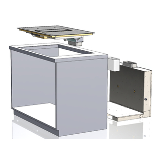
MONTAGEANLEITUNG Montagevorbereitung 1. Dichtungsband an der Auflageflächen umlaufend anbringen. 2. Front bzw. Schubladen des Unter - schrankes abnehmen. 3. Lüftermotor und Abluftschalldämpfer montieren ( 10 x Torx 4,2x9,5 ) . 4. Naber-Kanal kürzen - Distanz X - 30mm . - Seite 22 5. Vor dem Einbau den passenden Verschlussdeckel auswählen und das Tiefenmaß ein- stellen. Führungskante Schrankkorpus - Rückwand Führungskante Schrankkorpus - Lüfterfront Führungskante Schrankkorpus - Lüfterrückseite min. - max.: 484 - 515mm min. - max.: 454 - 484mm min. - max.: 425 - 454mm min.
- Seite 23 6. Kochfeld zur Rückseite geneigt einführen und einsetzen. 7. Kochfeld ausrichten, Silikonfuge (~2mm) ausfüllen Stutzenauszug einstellen...
- Seite 24 8. Lüftermotor inkl. Schalldämpfer in die Rückseite des Schrankes einbauen. 9. Naber-Kanal ablängen und montieren. Mit Klebeband abdichten. 10. Elektrischen Anschluss durch Fachpersonal erstellen ! - Sicherungsautomaten im Hausverteilerkasten abschalten ! - Kochfeldzuleitung anschließen (10) , - Ventilatorsteuerungs-Netzspannungsleitung (9) einstecken, - Flachbandkabel Steuerleitung (11) verbinden, - Motor-Zuleitungen (7+8) einstecken.
-
Seite 25: Allgemeine Themen
Inbetriebnahme 12. Sicherungsautomaten im Hausverteilerkasten einschalten ! Funktionstest anhand der Bedienungsanleitung durchführen ! Nach dem Anlegen der Versorgungsspannung (Netzanschluss) erfolgt zuerst ein Selbsttest der Steuerung und es wird eine Serviceinformation für den Kundendienst angezeigt. Wichtig: Zum Netzanschluss dürfen keine Gegenstände auf den Touch-Control Sensor- ALLGEMEINE THEMEN Reinigung... - Seite 26 Please carefully read the following information and explanations on the proper use of your new GUTMANN hood before using the appliance for the first time. Please also read our operating and installation instructions as well as the cleaning recommendations to ensure that you enjoy many years of service from your appliance.
- Seite 27 CONTENTS SEITE PRELIMINARY REMARKS Warning notices / symbols / assembly material / tools : Safety instructions : Scope of delivery - mounting accessories : PRODUCT DESCRIPTION Dimensional drawings hob : Dimensional drawings for installation of base cabinet : 32 - 33 Fan dimensional drawings : Product components : 34 - 35...
-
Seite 28: Preliminary Notes
PRELIMINARY NOTES Warning notes and symbols Warnings in these operating instructions are placed in front of an instruction that may result in personal injury or property damage. Measures to avert a hazard must be observed. WARNING MEANING SIGNS Warning of a danger spot ! Indicates potentially dangerous situations. -
Seite 29: Safety Instructions
PRELIMINARY NOTES Safety instructions Installation, connection, startup and repairs may be carried out by technicians only. Technicians can specify a suitable attachment and exhaust air conduction for the extractor hood. The attach- ment must be suitable for the weight of the extractor hood and for the load on the wall. Observe the pullout values of the supplied wall plugs. -
Seite 30: Scope Of Delivery - Mounting Accessories
Scope of delivery - mounting accessories: Fonda hob with downdraft ventilation 10 Torx screws Fan motor unit Exhaust silencer Item number: 41986500 Condensate filter with a tub Grease filter Fine dust odor filter Item no .: 4338 Art.No .: 4465 Art.Nr .: 4303 (optional) Naber Canal Tape 40-50mm... - Seite 31 Dimensional drawings of hobs: Worktop thickness 15-25 sideview frontview Worktop thickness 15-40...
- Seite 32 Dimensional drawings for installation of base cabinet : extension depth extension depth extension depth 800/830 thin worktop 800/830 thin worktop extension depth extension depth 800/830 thin worktop 800/830 thin worktop...
- Seite 33 Duct front min: Duct front min: Device dimension min: Device dimension min: Duct front max: Duct front max: Device dimension max: Device dimension max: Duct front min: Duct front min: Device dimension min: Device dimension min: Duct front max: Duct front max: Device dimension max: Device dimension max: Dimension drawing fan:...
-
Seite 34: Product Description
PRODUCT DESCRIPTION FONDA C-Version Product components 1 Hob with hob ventilation FONDA 9 Electrical connection control 2 Control panel touch sensor 10 Electrical connection hob 3 Safety glass, variable 11 Control line control panel adjustable (Item No .: 4304) 12 Hub channel (pass length) (Art.Nr .: TZ 8001) 4 Control 13a Condensation filter - 5 Fan motor... - Seite 35 3 - 13a - 13b - 14 - 15 Filter removal - sequence Grease filter (14) and acti- vated carbon Filters (15) are located insi- de the device at the bottom of the intake manifold. (Sectional view) Filterinstallation - seqence 15 - 14 - 13b - 13a - 3...
- Seite 36 ASSEMBLY REQUIREMENTS - worktop - base cabinet Safety instructions for the kitchen furnitu- The cooktop must not be installed above • re fitter refrigerators, dishwashers, washing ma- • Veneers, adhesives or plastic coverings of chines or dryers. adjacent furniture must be temperature- It must be ensured that no flammable, •...
- Seite 37 Worktop cut-out The cut-out in the worktop should be made as accurately as possible with a good, straight saw blade or a router. The cut surfaces should then be sealed to prevent moisture from penetrating. The cut-out for the hob is made according to the illustrations. The glass-ceramic hob surface must be flat and flush.
- Seite 38 2800 ML 800 - worktop 15-25 / 15-20 mm Surfaces flush mounting Cutout for Fonda 800 x 520 Worktop thickness 15 - 25 mm Surfaces mounting Cutout for Fonda 800 x 520 Worktop thickness 15 - 20 mm...
- Seite 39 2841 ML 800 - worktop15-40 / 15-35 Surfaces flush mounting Cutout for Fonda 800 x 520 Worktop thickness 15 - 40 mm Surfaces mounting Cutout for Fonda 800 x 520 Worktop thickness 15 - 35 mm...
- Seite 40 2800 ML 830 - worktop 15-25 / 15-20mm Surfaces flush mounting Cutout for Fonda 830 x 515 Worktop thickness 15 - 25 mm Surfaces mounting Cutout for Fonda 830 x 515 Worktop thickness 15 - 20 mm...
- Seite 41 2841 ML 830 - worktop 15-40 / 15-35mm Surfaces flush mounting Cutout for Fonda 830 x 515 Worktop thickness 15 - 40 mm Surfaces mounting Cutout for Fonda 830 x 515 Worktop thickness 15 - 35 mm...
- Seite 42 2800 ML 900 - worktop 15-25 / 15-20mm Surfaces flush mounting Cutout for Fonda 900 x 580 Worktop thickness 15 - 25 mm Surfaces mounting Cutout for Fonda 900 x 580 Worktop thickness 15 - 20 mm...
- Seite 43 2841 ML 900 - worktop 15-40 / 15-35mm Surfaces flush mounting Cutout for Fonda 900 x 580 Worktop thickness 15 - 40 mm Surfaces mounting Cutout for Fonda 900 x 580 Worktop thickness 15 - 35 mm...
- Seite 44 Installation requirement - electrical connection Connecting cable built in by factory WARNING AGAINST ELECTRICAL TENSION! • The hob is equipped with a temperature- THERE IS DANGER TO LIFE ! resistant connection cable at the facto- There are energised parts near this sym- •...
-
Seite 45: Assembly Preparation
ASSEMBLY INSTRUCTIONS Assembly preparation 1. Apply sealing tape all around the contact surface. 2. Remove the front or drawers of the base unit. Motor housing Silencer 3. Mount the fan motor and exhaust air silencer (10 x Torx 4.2x9.5). 4. Shorten the Naber canal - Distance X - 30mm. - Seite 46 5. Before installing, select the appropriate sealing cap and set the depth dimension. Leading edge of cabinet body - rear wall FLeading edge of cabinet body - fan front Leading edge of cabinet body - back of fan min. - max.: 484 - 515mm min.
- Seite 47 6. Insert and insert the hob at an angle to the rear. 7. Align the hob, fill in silicone joint (~ 2mm) ! Be sure to insert the cover ! Adjust nozzle extension...
- Seite 48 8. Install the fan motor including the silencer in the rear of the cabinet. 9. Cut the Naber canal to length and mount it. Seal with tape. 10. Make the electrical connection by qualified personnel ! - Switch off the automatic circuit breaker in the house distri- bution box ! - Connect the hob supply line (10), - Plug in the fan control mains voltage line (9),...
-
Seite 49: Environmental Information
Environmental information All models manufactured by GUTMANN are identified in accordance with European Directi- ve 2002/96/EC on waste electrical and electronic equipment (WEEE). This directive spe- cifies the framework for the EU-wide return and disposal of used appliances. Please ask y- our dealer for information about current disposal methods. - Seite 52 Energy label data and product datasheets can be viewed on our website at www.gutmann-exklusiv.eu. The reproduction, modifi- cation, utilisation and/or dissemination of the information published herein without prior, written authorisation having been provid-...