Monacor security SAG-42 Bedienungsanleitung
Alarmeinheit
Quicklinks
®
D
A
CH
Alarmeinheit
Bitte lesen Sie diese Anleitung vor der In stal lation gründ-
lich durch und heben Sie sie für ein späteres Nachlesen
auf.
1 Einsatzmöglichkeiten
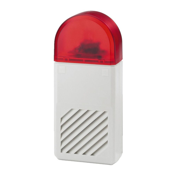
Die Alarmeinheit SAG-42 ist eine Kombination aus einer
Piezo-Sirene und einer Blitzleuchte. Sie wird in Alarman-
lagen als akustischer und optischer Alarmgeber einge-
setzt.
Die Alarmeinheit ist für den Innen- und Außeneinsatz
geeignet. Das Gehäuse besteht aus schlagfestem, UV-
beständigem Polycarbonat.
2 Wichtige Hinweise für den Gebrauch
Das Gerät entspricht allen erforder lichen Richt linien der
EU und ist deshalb mit
gekennzeichnet.
G
Schützen Sie das Gerät vor extremen Temperaturen
(zulässiger Einsatztemperaturbereich -10 °C bis +50 °C).
G
Wird das Gerät zweckentfremdet, nicht richtig installiert
oder nicht fachgerecht re pariert, kann keine Haftung für
daraus resultieren de Sach- oder Personenschäden und
keine Garantie für das Gerät übernommen werden.
Soll das Gerät endgültig aus dem Betrieb
genommen werden, übergeben Sie es zur
umweltfreundlichen Entsorgung einem ört -
lichen Re cyclingbetrieb.
3 Installation
1) Zum Öffnen der Alarmeinheit zuerst das Gehäuse-
oberteil (3) mit Kraft etwas nach unten schieben,
sodass es sich dann anschließend abnehmen lässt
(Pfeil A in Abb. 1).
2) Das Gehäuseunterteil (4) an die vorgesehene Monta-
gestelle halten, die Bohrlöcher (5) anzeichnen und
bohren. Zur zusätzlichen Befestigung können bei
Bedarf die vorgestanzten Durchbrüche (11) nach dem
Aufbohren verwendet werden.
Alarm Unit
GB
Please read these operating instructions carefully prior to
installing the unit and keep them for later use.
1 Applications
The alarm unit SAG-42 combines a piezo siren and a
strobe light. It is used as an audible and visible alarm
device in alarm systems.
The alarm unit is suitable for indoor and outdoor applica-
tions. The housing is made of shock-resistant and UV-
resistant polycarbonate.
2 Important Notes
This unit corresponds to all required directives of the EU
and is therefore marked with
.
G
Protect the unit against extreme temperatures (admissi-
ble ambient temperature range -10 °C to +50 °C).
G
No guarantee claims for the unit and no liability for any
resulting personal damage or material damage will be
accepted if the unit is used for other purposes than orig-
i nally intended, if it is not correctly installed or not
repaired in an expert way.
If the unit is to be put out of operation defini -
tively, take it to a local recycling plant for a dis-
posal which is not harmful to the environment.
3 Installation
1) To open the alarm unit, first push the upper part of the
housing (3) slightly downwards in a powerful move-
ment so that it can be removed (arrow A in fig. 1).
2) Hold the lower part of the housing (4) to the desired
mounting location, mark the position of the drill holes
(5), then drill the holes. If additional fixing is required,
drill open the predetermined breaking points (11).
3) Lead the cables coming from the alarm control panel
from the rear through the opening (8).
4) Screw the lower part of the housing to the wall.
SAG-42
3) Die von der Alarmzentrale kommenden Anschlusskabel
von hinten durch die Öffnung (8) führen.
4) Das Gehäuseunterteil an der Wand festschrauben.
5) Die Anschlusskabel mit einer Kabelschelle an der
Lasche (7) befestigen. Zur besseren Handhabung lässt
sich dazu das Anschlussmodul (9) durch Ausrasten der
Haltenasen (6) abnehmen.
6) Den Anschluss nach Abb. 3 durchführen. Dabei un be -
dingt auf die richtige Polarität achten, sonst ist durch
die internen, in Reihe geschalteten Schutzdioden
keine Funktion möglich.
Die Sabotageschleife mit den Klemmen 5 und 6
verbinden [Sabotagekontakt (13) = Öffner/NC] und
die An schlüsse für die Sirene (10) mit den Klemmen 3
(Minuspol) und 4 (Pluspol). Die Anschlüsse für die
Blitzleuchte mit den Klemmen 1 (Minuspol) und
2 (Pluspol) verbinden.
7) Das Gehäuseoberteil um ca. 5 mm nach unten versetzt
auf das Unterteil setzen und nach oben schieben
(Pfeil B in Abb. 1).
8) Die Alarmeinheit auf Funktion testen.
Sollte sich Schwitzwasser im Gehäuse bilden, kann
der vorgestanzte Durchbruch (12) herausge brochen
werden. Zusätzlich oder alternativ lässt sich oben an
der roten Kuppel ein Loch durchbrechen, wenn die
Alarmeinheit an einer wettergeschützten Stelle mon-
tiert ist.
9) Zuletzt das Gehäuseoberteil mit den beiden beiliegen-
den Schrauben (1) festschrauben und die Plomben (2)
einsetzen.
4 Technische Daten
Schalldruck: . . . . . . . . . . . . > 100 dB
Blitzenergie: . . . . . . . . . . . . 2,5 Ws
Stromversorgung: . . . . . . . . 12 V
Gehäuseschutzklasse: . . . . IP 34
Abmessungen, Gewicht . . . 110 × 260 × 65 mm, 500 g
Änderungen vorbehalten.
5) Fasten the connection cables to the lug (7) via a cable
clip. To facilitate handling, remove the connection mod-
ule (9) by unlocking its latches (6).
6) Make the connection according to fig. 3. Always
observe the correct polarity, otherwise a function will be
impossible due to the internal protective diodes con-
nected in series.
Connect the anti-tampering loop to the terminals 5
and 6 [anti-tampering contact (13) = NC contact] and
the siren connections (10) to the terminals 3 (negative
pole) and 4 (positive pole). Connect the strobe light
connections to the terminals 1 (negative pole) and 2
(positive pole).
7) Place the upper part of the housing on the lower part,
slightly displaced downwards by approx. 5 mm, and
push it upwards (arrow B in fig. 1).
8) Check the function of the alarm unit.
In case of condensation water accumulating within
the housing, remove the predetermined breaking piece
(12). If the alarm unit is installed in a weatherproof
place, a hole can be made in the red dome at the top,
either additionally or alternatively.
9) Finally fasten the upper part of the housing by means
of the two screws (1) supplied and insert the seals (2).
4 Specifications
SPL: . . . . . . . . . . . . . . . . . . > 100 dB
Strobe energy: . . . . . . . . . . 2.5 Ws
Power supply: . . . . . . . . . . . 12 V
Protection class of housing: IP 34
Dimensions, weight: . . . . . . 110 × 260 × 65 mm, 500 g
Subject to technical modification.
®
MONACOR INTERNATIONAL GmbH & Co. KG • Zum Falsch 36 • 28307 Bremen • Germany
Copyright
©
by MONACOR INTERNATIONAL. All rights reserved.
Best.-Nr. 04.3090
Œ
/200 mA (Blitz)
12 V
/370 mA (Sirene)
/200 mA (strobe)
12 V
/370 mA (siren)
rot
red
Ž
Gehäuseoberteil abnehmen (A) / aufsetzen (B)
Removing (A) / Replacing (B) the upper part of the housing
Innenansicht • Interior view
zur Blitzlampe
to strobe lamp
rot • red
schwarz • black
1
6
schwarz • black
zur Sirene • to siren
Anschlüsse • Connections
A-0468.99.03.08.2011
1
2
3
4
5
6
7
8
9
10
11
12
13
Blitz
Strobe
Sirene
Siren
Sabotage
Anti-tamper

Verwandte Anleitungen für Monacor security SAG-42


Inhaltszusammenfassung für Monacor security SAG-42
- Seite 1 Anschlüsse • Connections 4) Screw the lower part of the housing to the wall. Subject to technical modification. ® MONACOR INTERNATIONAL GmbH & Co. KG • Zum Falsch 36 • 28307 Bremen • Germany Copyright © by MONACOR INTERNATIONAL. All rights reserved.
- Seite 2 Ž Branchements • Connessioni larme. Con riserva di modifiche tecniche. ® MONACOR INTERNATIONAL GmbH & Co. KG • Zum Falsch 36 • 28307 Bremen • Germany Copyright © by MONACOR INTERNATIONAL. All rights reserved. A-0468.99.03.08.2011...
- Seite 3 Ž Conexiones • Podłączenia dzenia. Z zastrzeżeniem do możliwych zmian. ® MONACOR INTERNATIONAL GmbH & Co. KG • Zum Falsch 36 • 28307 Bremen • Germany Copyright © by MONACOR INTERNATIONAL. All rights reserved. A-0468.99.03.08.2011...