Honeywell R295HP-F Einbauanleitung
Verfügbare Sprachen
Verfügbare Sprachen
Quicklinks
1
1
Absperrventil
2
Schmutzfänger FY 69
3
Federhaube
4
grüne Federkappe
5
Absperrventil
6
Ablauftrichter
7
Entleerungsventil (bauseits)
20 hydraulisches Umschaltventil
Einbau-Anleitung • Installation Instructions
4
3
2
7
1
2
3
4
5
6
7
20 hydraulically actuated changeover valve
R295HP-F
20
Tropfwasser-
anschluss
6
Shutoff valve
Y-strainer FY 69
Spring bonnet
Green spring cap
Shutoff valve
Discharge tundish
Small drain cock (not included)
5

Verwandte Anleitungen für Honeywell R295HP-F


Inhaltszusammenfassung für Honeywell R295HP-F
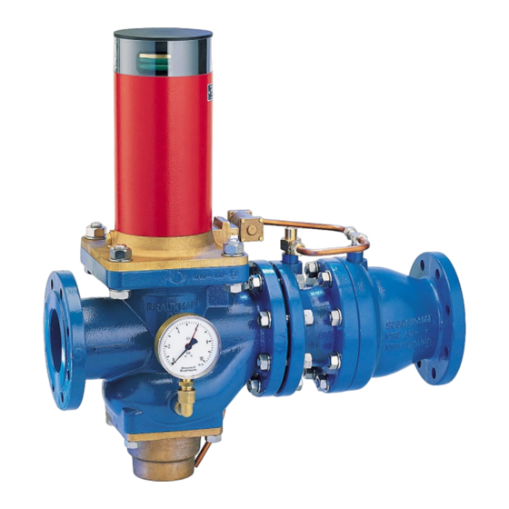
- Seite 1 R295HP-F Einbau-Anleitung • Installation Instructions Tropfwasser- anschluss Absperrventil Shutoff valve Schmutzfänger FY 69 Y-strainer FY 69 Federhaube Spring bonnet grüne Federkappe Green spring cap Absperrventil Shutoff valve Ablauftrichter Discharge tundish Entleerungsventil (bauseits) Small drain cock (not included) 20 hydraulisches Umschaltventil...
- Seite 2 1. Einbau an. Übersteigt der Differenzdruck 0,5 bar, so er- folgt die hydraulische Umsteuerung des Steuer- Beim Einbau sind die örtlichen Vorschriften, sowie ventils, und der Rohrtrenner schaltet auf Durch- allgemeine Richtlinien und die Einbau-Anleitung zu flussstellung. Nach Beendigung der Wasserent- beachten.
- Seite 3 5. Instandhaltung Von einem Installationsunternehmen durch- zuführen. Das Zeitintervall jährlich nach DIN EN 806-5 Anhang A ist abhängig von den örtlichen Betriebsbedingungen. Vorsicht Verletzungsgefahr. Innenliegende Teile können herausgeschleudert werden. 5.1 Ventileinsatz austauschen 1. Absperrventile 1 und 5 schließen. 2. Armatur druckentlasten (z.B durch Öffnen des Entleerungsventils 7 ).
- Seite 4 6. Technische Daten Verwendungsbereich: Trinkwasser (PWC) Vordruck: max. 16 bar Einbaulage: waagrecht, Federhaube nach oben Betriebstemperatur: bis 40 °C Δp = 0,5 bar Ansprechdruck: Mindestdurchflussmenge: 1l/min Min. Eingangsdruck: 1,5 bar Anschlussgrößen: DN 65 bis 200 Anschluss /h bei Δp = 0,8 bar Nenndurchfluss m -Wert ζ-Wert...