Herunterladen Inhalt Inhalt Diese Seite drucken

Werbung

Verfügbare Sprachen
  • DE

Verfügbare Sprachen

  • DEUTSCH, seite 29
BlueSolar PWM Charge Controller – LCD - USB
12V | 24V | 5A
12V | 24V | 10A
12V | 24V | 20A
Manual
Handleiding
Manuel
Anleitung
Manual
Manual
Manuale

Werbung

Inhaltsverzeichnis
loading

Inhaltszusammenfassung für Victron energy BlueSolar PWM Serie

  • Seite 1 Manual Handleiding Manuel Anleitung Manual Manual Manuale BlueSolar PWM Charge Controller – LCD - USB 12V | 24V | 5A 12V | 24V | 10A 12V | 24V | 20A...
  • Seite 3: General Information

    1. General Information IMPORTANT Always connect the battery first, in order to allow the Controller • to recognize system voltage Use a 12V (36 cells) solar array for a 12V system. • Use a 24V (72 cells) solar array for a 24V system. •...
  • Seite 4 1. Connect the battery - plus and minus. 2. Connect the solar array - plus and minus. 3. Connect the load - plus and minus. The reverse order applies when deinstalling. An improper sequence order can damage the BlueSolar PWM Charge Controller! 1.
  • Seite 5 4. LCD DISPLAY and SETTINGS MENU:switch between different display, or to enter/exit setting by long press. UP:press to change the settings when in setting mode. DOWN: press to change the settings when in setting mode. Load on/off button when in H mode. 4.1 Monitoring and settings Values between [ ] are for 24V battery settings Boot Display.
  • Seite 6 Main display: battery voltage, battery state of charge, charging and discharging status. Press MENU to enter next display. Change settings in Main display. Battery type setting. See table below. Press the MENU button for several seconds until the The factory setting is b01 display flashes, you are in: Battery...
  • Seite 7 PV Voltage display: PV voltage and the state of charge of the battery. Press MENU to enter next display. Charge current display: PV to battery current and the state of charge of the battery. Press MENU to enter next display. Load output settings.
  • Seite 8 Short-circuit protection setting. Some inductive or capacitive loads will trigger the short-circuit protection during start up. Press MENU to enter Therefore the SC-protection can be disabled the next display manually. Sc.F = OFF, Sc.n = ON. The default is ON. Discharge current display: load current and battery capacity, Press MENU to enter next display.
  • Seite 9 Over-current protection. A load output over-current or short-circuit is indicated by a flashing load icon. The controller will disable the load output and try to re- enable after 30 seconds. Shut down after 60s in case of 110%-130% load. Shut down after 5s in case of 130%-160% load. Short circuit protection In case of a short circuit the controller will switch off the load output and wait for 30s and then try to restart.
  • Seite 10: Specifications

    6.Specifications 12V|24V|5A 12V|24V|10A 12V|24V|20A BlueSolar PWM Charge Controller Battery Voltage 12/24V Auto Select Charge & Load Current Charge mode PWM, Time and Lighting Control Automatic load disconnect Maximum solar array voltage Solar voltage range 15-28V [30-55V] Self-consumption <10mA Reverse polarity connection of the solar panels. Reverse polarity connection of the battery.
  • Seite 11: Algemene Informatie

    1. Algemene Informatie BELANGRIJK Altijd eerst de accu aansluiten, teneinde de • Besturingseenheid het herkennen van het spanningssysteem mogelijk te maken Gebruik een 12V (36 cellen) zonnepaneel voor een 12V • systeem. Gebruik een 24V (72 cellen) zonnepaneel voor een 24V •...
  • Seite 12 1. Sluit de accu aan - plus- en minteken. 2. Sluit het zonnepaneel aan - plus- en minteken. 3. Sluit de stroom aan - plus- en minteken. De omgekeerde volgorde is van toepassing bij het demonteren. Een onjuiste volgorde kan de BlueSolar PWM Laadregelaar beschadigen! 1.
  • Seite 13 4. LCD-SCHERM en INSTELLINGEN MENU:schakelen tussen verschillende weergaven of om de instelling te openen/sluiten door lang in te drukken. OMHOOG:indrukken om de instellingen te wijzigen in de instellingsmodus. OMLAAG: indrukken om de instellingen te wijzigen in de instellingsmodus. Laden aan-/uitknop wanneer in H-modus. 4.1 Monitoring en instellingen Waarden tussen [ ] zijn voor 24V-accu instellingen Opstartscherm.
  • Seite 14 Hoofdscherm: accuspanning, accustatus van opladen, laad- en ontlaadstatus. Druk op MENU om naar het volgende scherm te gaan. Wijzig de instellingen in het Instelling accutype. Hoofdscherm. Zie onderstaande tabel. Druk op gedurende enkele seconden op de MENU knop totdat het display De fabrieksinstelling is b01 knippert, u bevindt zich in: Accutype...
  • Seite 15 PV-spanningsdisplay: PV-spanning en de ladingstoestand van de accu. Druk op MENU om naar het volgende scherm te gaan. Laadstroomdisplay: PV naar accustroom en laadtoestand van de accu. Druk op MENU om naar het volgende scherm te gaan. Laad de uitgangsinstellingen. De fabrieksinstelling is 24 uur (laaduitgang altijd aan) Wijzig de instellingen voor Laaduitgang instelling.
  • Seite 16 Activering Vertragingstijd Wanneer de laadregelaar een spanning van het zonnepaneel meet Druk op MENU die lager is dan de triggerwaarde, naar het volgende wordt deze 10 seconden vertraagd scherm te openen. en opnieuw gemeten om te zorgen dat het ´s nachts inschakelt. Fabrieksinstelling: 10 seconden Kortsluitbeveiligingsinstelling.
  • Seite 17 5. Alarmen Wanneer de temp. ≥ 85 ℃ is, zal de regelaar naar de eerste Hoge temperatuur beveiligingsfase gaan: het PV-invoervermogen zal verlaagd worden om de temperatuur te verminderen. Er is geen alarm op het LCD-beeld. Wanneer de temp. >90 ℃ is, zal de regelaar naar de tweede beveiligingsfase gaan: het PV-invoervermogen zal verminderd worden naar nul, de laaduitgang zal uitgeschakeld worden en een alarmpictogram voor hoge...
  • Seite 18 Open circuit in de laadregelaar • Intern defect. Open circuit in het laaduitgangcircuit Intern defect. • Bedradingsfout of kortsluiting in het laaduitgangcircuit Bedradingsfout: de minus van de laad en de • minus van de accu zijn onderling verbonden. Intern defect. •...
  • Seite 19 6.Specificaties BlueSolar PWM 12V|24V|5A 12V|24V|10A 12V|24V|20A Laadregelaar Accuspanning 12/24V Auto Selecteer Laden & Laadstroom Laadmodus PWM, Tijd- en Lichtregeling Automatische laadafsluiting Maximale zonne- energiespanning Zonnespanningsbereik 15-28V [30-55V] Eigen verbruik <10mA Omgekeerde polariteitsverbinding van de zonnepanelen. Omgekeerde polariteitsverbinding van de accu. Ontkoppeling met lage spanning.
  • Seite 20: Consignes Générales

    1. Consignes générales IMPORTANT Toujours connecter les batteries en premier. • Pour un système de batterie de 12 V, n'utilisez que le • dispositif de panneaux solaires de 12 V (36 cellules). Pour un système de batterie de 24 V, n'utilisez que le •...
  • Seite 21 1. Connectez la batterie – pôle positif et négatif. 2. Connectez le champ de panneaux solaires – pôle positif et négatif. 3. Connectez la charge consommatrice – pôle positif et négatif. Pour désinstaller, veuillez suivre les étapes en sens inverse. Inverser l'ordre de la séquence peut endommager Le contrôleur de charge BlueSolar PWM ! 1.
  • Seite 22 4. ÉCRAN LCD et PARAMÈTRES MENU : pour passer d'un écran à l'autre ou pour entrer/quitter la configuration en maintenant le bouton appuyé. UP : appuyez pour modifier les paramètres lorsque vous êtes en mode Configuration. DOWN : appuyez pour modifier les paramètres lorsque vous êtes en mode Configuration.
  • Seite 23 Écran principal : tension de batterie, état de charge de la batterie, statut du processus de charge et décharge. Appuyez sur MENU pour passer à l'écran suivant. Modifier les paramètres sur Configuration du type de batterie. l'écran principal. Voir le tableau ci-dessous. Appuyez sur le bouton MENU pendant...
  • Seite 24 Appuyez à nouveau Reconnexion en cas de tension sur la touche MENU faible Le réglage standard est 12,6 V pour arriver dans : [25,2 V] Écran de tension PV : Tension PV et état de charge de la batterie. Appuyez sur MENU pour passer à...
  • Seite 25 Phoenix VE.Direct s'il fait jour pour allumer ou éteindre peuvent être contrôlés en la charge. raccordant la connexion Le réglage standard est 4 V. de gauche du contrôle à distance á la sortie de la charge). Temps de retard du déclenchement Lorsque le contrôleur de charge mesure une tension sur les...
  • Seite 26 5. Alarmes Température élevée Lorsque la température atteint ou dépasse 85 °C, le contrôleur active la première phase de protection : il réduit le courant d’alimentation PV pour baisser la température. Aucune alarme n'apparait sur l'écran LCD. Lorsque la température atteint ou dépasse 90 °C, le contrôleur active la seconde phase de protection : il réduit et coupe le courant d’alimentation PV, il désactive la sortie de charge et affiche une icône de température élevée sur...
  • Seite 27 Circuit ouvert dans le contrôleur de charge Panne interne. • Circuit ouvert dans le circuit de sortie de charge Panne interne. • Erreur de câblage ou court-circuit dans le circuit de sortie de charge Erreur de câblage : la borne (-) de la charge est •...
  • Seite 28: Caractéristiques

    6. Caractéristiques 12 V | 24 V | 5 A 12 V | 24 V | 10 A 12 V | 24 V | 20 A Contrôleur de charge BlueSolar PWM 12 V 24 V 12 V 24 V 12 V 24 V Tension de batterie Sélection automatique 12/24 V...
  • Seite 29: Allgemeine Informationen

    1. Allgemeine Informationen WICHTIGER HINWEIS Schließen Sie die Batterie immer zuerst an, damit der Regler die • Systemspannung erkennen kann. Verwenden Sie eine Solaranlage mit 12 V (36 Zellen) für ein 12 V • System. Verwenden Sie eine Solaranlage mit 24 V (72 Zellen) für ein 24 V •...
  • Seite 30 1. Batterie anschließen - Plus und Minus. 2. Solaranlage anschließen - Plus und Minus. 3. Last anschließen - Plus und Minus. Beim Deinstallieren umgekehrt vorgehen. Bei Nichteinhaltung der richtigen Abfolge kann der BlueSolar PWM Lade-Regler beschädigt werden. 1. Achten Sie darauf, dass Ihre Batterie vor der Erstinstallation geladen ist, damit der BlueSolar PWM Lade-Regler den Batterietyp erkennen kann.
  • Seite 31: Lcd- Display Und Einstellungen

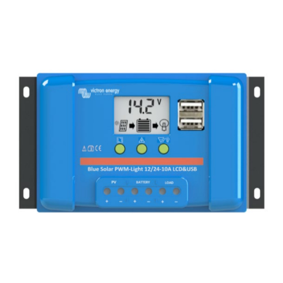
    4. LCD- Display und Einstellungen MENÜ:Zwischen verschiedenen Anzeigen hin- und herschalten oder Aufrufen/Verlassen der Einstellungen durch anhaltendes Drücken. HOCH: im Einstellungsmodus lassen sich damit die Einstellungen ändern. RUNTER: im Einstellungsmodus lassen sich damit die Einstellungen ändern. Taste Last ein/aus im H-Modus 4.1 Überwachung und Einstellungen Die Werte zwischen [ ] sind für 24 V-Batterieeinstellungen.
  • Seite 32 Hauptbildschirm: Batteriespannung, Ladezustand der Batterie, Lade- und Entladestatus. Durch Betätigen der Taste MENU gelangen Sie zum nächsten Bildschirm. Änderung der Einstellungen im Hauptanzeigebildsch Halten Sie die Einstellung des Batterietyps: Siehe Tabelle unten. Taste MENU einige Sekunden lang gedrückt, bis die Die Werkseinstellung ist b01.
  • Seite 33 Anzeigebildschirm PV-Spannung: PV-Spannung und Ladezustand der Batterie. Durch Betätigen der Taste MENU gelangen Sie zum nächsten Bildschirm. Anzeigebildschirm Ladestrom: Strom PV zu Batterie und Ladezustand der Batterie. Durch Betätigen der Taste MENU gelangen Sie zum nächsten Bildschirm. Einstellungen Lastausgang Die Werkseinstellung ist 24 h (Lastausgang ist immer an). Ändern der Einstellungen Einstellung Lastausgang...
  • Seite 34 Verzögerungszeit für das Auslösen Misst der BlueSolar PWM Lade- Regler einen Spannungswert eines Durch Betätigen der Solarmoduls unterhalb des Taste MENU Auslösewerts, wartet er 10 Sekunden gelangen Sie zum lang und misst erneut, um nächsten Bildschirm. sicherzugehen, dass die Nacht anbricht.
  • Seite 35 5. Alarme Hohe Temperatur Bei einer Temperatur ≥ 85℃ schaltet sich der BlueSolar PWM Lade-Regler in die erste Schutzphase: Er verringert den PV- Eingangsstrom, um die Temperatur zu senken. Es erscheint kein Alarm auf dem LCD-Display. Bei einer Temperatur >90℃ schaltet sich der BlueSolar PWM Lade-Regler in die zweite Schutzphase: Der PV- Eingangsstrom wird auf null heruntergeregelt, der Lastausgang wird abgeschaltet und auf dem LCD-Bildschirm...
  • Seite 36 Offener Stromkreis im Laderegler Interner Defekt. • Offener Stromkreis im Lastausgangskreis Interner Defekt. • Verdrahtungsfehler oder Kurzschluss im Lastausgangskreis Verdrahtungsfehler: der Minuspol der Last und der • Minuspol der Batterie sind miteinander verbunden. Interner Defekt. •...
  • Seite 37: Technische Daten

    6. Technische Daten 12 V|24 V|5 A 12 V|24 V|10 A 12 V|24 V|20A BlueSolar PWM Lade-Regler 12 V 24 V 12 V 24 V 12 V 24 V Batteriespannung 12/24 V automatische Wahl Lade- & Last-Strom 10 A 20 A Lade-Modus PWM, Zeit- und Beleuchtungsregelung Automatische...
  • Seite 39: Información General

    1. Información general IMPORTANTE Conecte siempre la batería en primer lugar para que el controlador • reconozca la tensión del sistema. Utilice paneles solares de 12V (36 celdas) para sistemas de 12V. • Utilice paneles solares de 24V (72 celdas) para sistemas de 24V. •...
  • Seite 40 1. Conecte la batería - positivo y negativo. 2. Conecte las placas solares - positivo y negativo. 3. Conecte la carga consumidora - positivo y negativo. A la hora de desinstalar, siga estos pasos a la inversa. ¡Si la secuencia no se hace en este orden el controlador de carga BlueSolar PWM podría quedar dañado! 2.
  • Seite 41 4. PANTALLA LCD y CONFIGURACIÓN MENU:salte entre las distintas pantallas, o introduzca/modifique ajustes manteniendo pulsado. UP (arriba):pulse para cambiar los ajustes cuando esté en modo configuración. DOWN (abajo):pulse para cambiar los ajustes cuando esté en modo configuración. Botón on/off de la carga consumidora cuando está en modo H.
  • Seite 42 4.1 Monitorización y configuración. Los valores entre [ ] corresponden a las baterías de 24V Pantalla de arranque. Tras conectar la batería la pantalla muestra el modelo de cargador solar y la tensión del sistema reconocidos por el cargador solar. 105=controlador de carga BlueSolar PWM –...
  • Seite 43 Pulse de nuevo en el Desconexión por baja tensión El ajuste de fábrica es 11,2V botón MENU [22,4V] podrá hacer modificaciones en: Pulse de nuevo en el Reconexión por tensión baja El ajuste de fábrica es 12,6V botón MENU [25,2V] podrá...
  • Seite 44 Pulse MENU para entrar en la siguiente Nivel de activación pantalla. Cuando el controlador de carga se (Nota: los inversores ajusta en L01-L23, medirá la tensión Phoenix VE.Direct pueden del panel solar para decidir si es de controlarse conectando la noche o de día para activar o conexión del lado izquierdo desactivar las cargas consumidoras.
  • Seite 45 5. Alarmas Cuando la temperatura ≥ 85 ℃, el controlador entrará en la Temperatura alta primera fase de protección: la corriente de entrada FV se reducirá para bajar la temperatura. La pantalla LCD no mostrará ninguna alarma. Cuando la temperatura >90 ℃, el controlador entrará en la segunda fase de protección: la corriente de entrada FV se reducirá...
  • Seite 46 Circuito abierto en el controlador de carga Fallo interno. • Circuito abierto en el circuito de salida de carga • Fallo interno. Error de cableado o cortocircuito en el circuito de salida de carga Error de cableado: el negativo de la carga y el •...
  • Seite 47: Especificaciones

    6. Especificaciones Controlador de carga 12V|24V|5A 12V|24V|10A 12V|24V|20A BlueSolar PWM Tensión de la batería Selección automática 12/24V Corriente de carga y cargas consumidoras Modo de carga PWM, Tiempo y Control de luminosidad Desconexión automática Sí de la carga Tensión FV máxima Rango de tensión FV 15-28V [30-55V] Autoconsumo...
  • Seite 49: Allmän Information

    1. Allmän information VIKTIGT Anslut alltid batteriet först så att kontrollern kan detektera • systemspänningen. Använd en 12 V (36 celler) solpanel i ett 12 V system. • Använd en 24V (72 celler) solpanel i ett 24V system. • BlueSolar PWM Laddningsregulatoreranvänder pulsbreddsmodulerad (PWM efter engelskans Pulse Width Modulation) laddningsspänningskontroll tillsammans med en laddingskontrollsalgoritm i flera steg.
  • Seite 50 1. Anslut batteriet - plus och minus. 2. Anslut solcellspanelen - plus och minus. 3. Anslut belastningen - plus och minus. Vid avinstallering gäller omvänd ordning. En felaktig ordning kan skada laddningsregulatorn BlueSolar! 1. Säkerställ att batteriet är laddat så att BlueSolar PWM Laddningsregulatorerkan känna igen batteritypen innan den första installationen.
  • Seite 51 4. LCD-DISPLAY och INSTÄLLNINGAR MENY: växla mellan olika displayer eller tryck ned länge för att gå in/ur inställningar. UPP: tryck för att ändra inställningar när den är i inställningsläge. NED: tryck för att ändra inställningar när den är i inställningsläge. Belastning av/på-knapp när den är i H-läge.
  • Seite 52 4.1 Övervakning och inställningar Värden inom [ ] är för inställningar för 24 V-batterier. Startdisplay. Efter att batteriet har anslutits visar skärmen vilken modell solcellsladdaren är samt vilken systemspänning laddaren känner av. 105=BlueSolar PWM laddningsregulator – LCD – USB 12 V|5 A 205=BlueSolar PWM laddningsregulator –...
  • Seite 53 Tryck återigen ner Låg spänning frånkoppling Fabriksinställningen är 11,2 V [22,4 V] MENY- -knappen och du hamnar i: Tryck återigen ner Låg spänning återinkoppling Fabriksinställningen är 12,6V [25,2V] MENY- -knappen och du hamnar i: Display för solcellsspänning: Solcellsspänning och batteriets laddningstillstånd.
  • Seite 54 Tryck ned MENY Utlösningsnivå knappen för att gå vidare När BlueSolar PWM till nästa display Laddningsregulatorerär inställd på L01 (Obs: Växelriktarna Phoenix L23 kommer spänningen i solcellspanelen VE.Direct kan styras genom att mätas för att bestämma om det är natt att kopplas till anslutningen eller dag för att koppla på...
  • Seite 55 5. Larm När temperaturen är ≥ 85 ℃, kommer BlueSolar PWM Hög temperatur Laddningsregulatoreratt gå in i första skyddsfasen, den kommer att sänka ingångsströmmen på solcellspanelen för att sänka temperaturen. LCD-displayen visar inte något larm. När temperaturen är >90 ℃, kommer laddningsregulatorn att gå in i andra skyddsfasen: ingångsströmmen för solcellspanelen kommer att sänkas till noll, belastningsutgången kommer att stängas av och ett larm om för hög temperatur visas på...
  • Seite 56 Kabelfel eller kortslutning i laddningsregulatorn Kabelfel: minus på solcellspanelen är kopplad till • batteriets minus. Invändig defekt. • Öppen krets i laddningsregulatorn Invändig defekt. • Öppen krets i utgångsbelastningskretsen Invändig defekt. • Kabelfel eller kortslutning i utgångsbelastningskretsen • Kabelfel: belastningens minus och batteriets minus är sammankopplade.
  • Seite 57 6. Specifikationer 12V|24V|5A 12V|24V|10A 12V|24V|20A Laddningsregulator Blue Solar PWM Batterispänning 12/24 volt autoval Laddnings- och 5m A belastningsström Laddningsläge PWM, tid- och ljuskontroll Automatisk frånkoppling av belastning Maximal solpanelsspänning Solpanelsintervall 15-28 V [30-55 V] Egenkonsumtion <10mA Omvänd polaritetsanslutning av solcellspaneler. Omvänd polaritetsanslutning av batteriet.
  • Seite 59: Informazioni Generali

    1. Informazioni Generali IMPORTANTE Connettere sempre prima la batteria, per consentire al • regolatore di riconoscere la tensione del sistema Utilizzare un pannello solare da 12 V (36 celle) per un sistema • da 12 V. Utilizzare un pannello solare da 24V (72 celle) per un sistema da •...
  • Seite 60 1. Collegare i poli positivo e negativo della batteria. 2. Collegare i poli positivo e negativo del pannello solare. 3. Collegare i poli positivo e negativo del carico. Per la disinstallazione si segue l’ordine inverso. Un diverso ordine della sequenza può danneggiare il Regolatore di carica PWM BlueSolar! 5.
  • Seite 61 4. DISPLAY LCD e IMPOSTAZIONI MENU: passare da un display all’altro o entrare/uscire dalle impostazioni premendolo a lungo. UP: premerlo per cambiare le impostazioni quando ci si trova nella modalità di configurazione. DOWN: premerlo per cambiare le impostazioni quando ci si trova nella modalità...
  • Seite 62 4.1 Monitoraggio e impostazioni I valori fra [ ] si riferiscono alle impostazioni di batterie da 24 V. Display di Avvio. Dopo aver collegato la batteria, il display mostra il modello del caricabatterie solare e la tensione del sistema rilevata dal caricabatterie solare. 105=Regolatore di carica PWM BlueSolar –...
  • Seite 63 Premere nuovamente Disconnessione per bassa tensione il tasto MENU e si Le impostazioni di fabbrica sono entra in: 11,2V [22,4V] Premere nuovamente Riconnessione per bassa tensione il tasto MENU e si Le impostazioni di fabbrica sono entra in: 12,6V [25,2V] Tensione FV mostra: La tensione FV e lo stato di carica della batteria.
  • Seite 64 Premere MENU Livello attivazione entrare nella seguente Quando il Regolatore di carica PWM schermata BlueSolar è impostato su L01-L23, si (Nota: gli inverter Phoenix misurerà la tensione del pannello solare per VE.Direct possono essere decidere se è notte o giorno e accendere o controllati collegando la spegnere il carico.
  • Seite 65 5. Allarmi Quando la temperatura è ≥ 85 ℃, il regolatore entra nella prima Temperatura alta fase di protezione: la corrente di ingresso FV verrà ridotta per abbassare la temperatura. Sul display LCD non viene visualizzato alcun allarme. Quando la temperatura è >90 ℃, il regolatore entra nella seconda fase di protezione: la corrente di ingresso FV viene ridotta, l’uscita del carico verrà...
  • Seite 66 Errore di cablaggio o cortocircuito nel regolatore di carica Errore di cablaggio: il meno del pannello solare è • collegato al meno della batteria. Difetto interno. Circuito aperto nel regolatore di carica • Difetto interno. Circuito aperto nel circuito di uscita del carico Difetto interno.
  • Seite 67 6. Specifiche 12V|24V|5A 12V|24V|10A 12V|24V|20A Regolatore di carica PWM BlueSolar Tensione della batteria 12/24V con selezione automatica Corrente di Carica e del Carico Modalità di carica PWM, Controllo Tempo e Illuminazione Disconnessione automatica del carico Sì Tensione massima pannello solare Campo di tensione solare 15-28V [30-55V] Autoconsumo...
  • Seite 69 EN - Mechanical drawing. NL - Mechanische tekening. FR - Schémas mécaniques. DE - Technische Zeichnung ES - Dibujo mecánico. SV - Mekanisk ritning. IT - Disegni meccanici...
  • Seite 71: Victron Energy

    Serial number: Version : 06 Date : August 18 , 2020 Victron Energy B.V. De Paal 35 | 1351 JG Almere PO Box 50016 | 1305 AA Almere | The Netherlands General phone : +31 (0)36 535 97 00 E-mail : sales@victronenergy.com...

Inhaltsverzeichnis