Inhaltsverzeichnis
Werbung
Verfügbare Sprachen
Verfügbare Sprachen
Quicklinks
Werbung
Kapitel
Inhaltsverzeichnis

Verwandte Anleitungen für Eaton ZB12/XTOB Serie


Inhaltszusammenfassung für Eaton ZB12/XTOB Serie
- Seite 1 Handbuch/Manual 03/15 MN03407004Z-DE/EN Motorschutzrelais ZB12/XTOB…BC1 und ZB32/XTOB…CC1 Überlastüberwachung von Ex e-Motoren Motor-protective relays ZB12/XTOB…BC1 and ZB32/XTOB…CC1 Overload monitoring of Ex e motors...
- Seite 2 Alle Rechte, auch die der Übersetzung, vorbehalten. Kein Teil dieses Handbuches darf in irgendeiner Form (Druck, Fotokopie, Mikrofilm oder einem anderen Verfahren) ohne schriftliche Zustimmung der Firma Eaton Industries GmbH, Bonn, reproduziert oder unter Verwendung elektronischer Systeme verarbeitet, vervielfältigt oder verbreitet werden.
- Seite 3 Gefahr! Danger! Gefährliche Dangerous elektrische electrical Spannung! voltage! Vor Beginn der Installationsarbeiten Before commencing the installation • Gerät spannungsfrei schalten • Disconnect the power supply of the device. • Gegen Wiedereinschalten sichern • Ensure relosing interlock that devices cannot be accidentally restarted. •...
- Seite 4 03/15 MN03407004Z-DE/EN Überblick/Overview Motorschutzrelais ZB12/XTOB…BC1 und ZB32/XTOB…CC1 Überlastüberwachung von Ex e-Motoren Motor-protective relays ZB12/XTOB…BC1 and ZB32/XTOB…CC1 Overload monitoring of Ex e motors Anhang/Appendix...
-
Seite 5: Inhaltsverzeichnis
03/15 MN03407004Z-DE/EN Inhalt Zu diesem Handbuch Zielgruppe Abkürzungen und Symbole Änderungsprotokoll Motorschutzrelais ZB12/XTOB…BC1 und ZB32/XTOB…CC1 Vorwort Geräteübersicht Gerätebeschreibung – Überlastschutz mit Bimetallrelais – Strombereiche der Motorschutzrelais – Temperaturkompensation – Phasenausfall – Wiedereinschaltung – Testfunktion Sicherheitstechnische Betrachtung Projektierung Überlastüberwachung von Motoren im Ex e-Bereich 17 Einstellung der Überstromschutzeinrichtung –... - Seite 6 03/15 MN03407004Z-DE/EN Inhalt Anhang/Appendix Typenschild/ Rating plate – Motorschutzrelais/Overload relay ZB12/XTOB…BC1 und/and ZB32/XTOB…CC1 Auslösekennlinien/ Tripping characteristics – ZB12-0,16/XTOBP16BC1 und/and ZB32-0,16/XTOBP16CC1 – ZB12-0,24/XTOBP24BC1 und/and ZB32-0,24/XTOBP24CC1 – ZB12-0,4/XTOBP40BC1 und/and ZB32-0,4/XTOBP40CC1 – ZB12-0,6/XTOBP60BC1 und/and ZB32-0,6/XTOBP60CC1 – ZB12-1/XTOB001BC1 und/and ZB32-1/XTOB001CC1 – ZB12-1,6/XTOB1P6BC1 und/and ZB32-1,6/XTOB1P6CC1 –...
-
Seite 7: Zu Diesem Handbuch
03/15 MN03407004Z-DE/EN Zu diesem Handbuch Das vorliegende Handbuch gilt für die Motorschutzrelais ZB12/XTOB…BC1 und ZB32/XTOB…CC1. Dieses Handbuch beschreibt die Überlastüberwachung zum Schutz von Ex e-Motoren in explosiongefährdeten Bereichen. Zielgruppe Dieses Handbuch richtet sich an Fachpersonal, das die Motorschutzrelais installiert, in Betrieb nimmt und wartet. Abkürzungen und Symbole In diesem Handbuch werden Abkürzungen und Symbole eingesetzt, die folgende Bedeutung haben: Ex e... -
Seite 8: Änderungsprotokoll
03/15 MN03407004Z-DE/EN Zu diesem Handbuch Achtung! warnt vor leichten Sachschäden. Warnung! warnt vor schweren Sachschäden und leichten Verletzungen. Gefahr! warnt vor schweren Sachschäden und schweren Verletzungen oder Tod. Für eine gute Übersichtlichkeit finden Sie auf den linken Seiten im Kopf die Kapitelüberschrift und auf den rechten Seiten den aktuellen Abschnitt, Ausnahmen sind Kapitel- anfangsseiten und leere Seiten am Kapitelende. - Seite 9 03/15 MN03407004Z-DE/EN Änderungsprotokoll Redaktions- Seite Stichwort geän- ent- datum dert fällt 10/10 diverse Typen XTOB… Tabelle 6, ZB32-24 Zuordnungsart „2“ Auslösekennlinie ZB32-16 03/15 diverse Typ ZB32-38 Sicherheitstechnische Betrachtung 96 - 99 Konformitätserklärungen...
- Seite 10 03/15 MN03407004Z-DE/EN...
-
Seite 11: Motorschutzrelais Zb12/Xtob
03/15 MN03407004Z-DE/EN Motorschutzrelais ZB12/XTOB…BC1 und ZB32/XTOB…CC1 Vorwort Für den Schutz von Motoren in explosionsgefährdeten Bereichen gelten zusätzlich zu den Vorschriften nach EN 60079-14 und VDE 0165 Teil 1 separate Vorschriften für die entsprechenden Zündschutzarten. Für Motoren in der Zündschutzart „e“„Erhöhte Sicherheit“ verlangt die Vorschrift EN 60079-7 zusätzliche Maßnahmen. -
Seite 12: Geräteübersicht
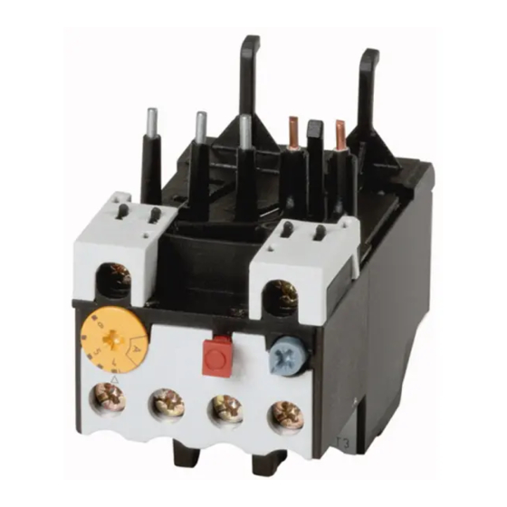
03/15 MN03407004Z-DE/EN Motorschutzrelais ZB12/XTOB…BC1 und ZB32/XTOB…CC1 Geräteübersicht Abbildung 1: Motorschutzrelais ZB12/XTOB…BC1 Abbildung 2: Motorschutzrelais ZB32/XTOB…CC1 Gerätebeschreibung Überlastschutz mit Bimetallrelais Die Motorschutzrelais ZB12/XTOB...BC1 und ZB32/XTOB…CC1 sind dreipolige elektromechanische Motorschutzrelais mit Bimetallen. Sie sind zur Überwachung von Gleich- und Wechselstrom geeignet. Die Motorschutzrelais ZB12/XTOB...BC1 und ZB32/XTOB…CC1 sind als Direktanbau an die Schütze DILM…/XTCE…... - Seite 13 03/15 MN03407004Z-DE/EN Gerätebeschreibung Zusätzlich ist das Relais ZB32/XTOB…CC1 in Kombination mit einer Einzelaufstellung einzeln einsetzbar. Tabelle 2: Einzelaufstellung Motorschutzrelais Einzelaufstellung ZB32-… XTOB…CC1 ZB32-XEZ XTOBXDINC Bei einer Überlastauslösung schalten die Hilfsschalter 95-96 und 97-98 um und unterbrechen den Steuerstromkreis des zugehörigen Leistungsschützes. Sie schalten so indirekt den Stromfluss des zu überwachenden Motors ab.
-
Seite 14: Strombereiche Der Motorschutzrelais
03/15 MN03407004Z-DE/EN Motorschutzrelais ZB12/XTOB…BC1 und ZB32/XTOB…CC1 Strombereiche der Motorschutzrelais Die Motorschutzrelais werden mit Hilfe einer Strom-Einstell- scheibe auf den Motornennstrom eingestellt. Mit verschiedenen Typen können Motoren von 0,1 bis 38 A Motornennstrom überwacht werden. Tabelle 3: Strombereiche ZB12/XTOB…BC1 Strombereich I [A] ZB12-0,16 XTOBP16BC1 0,1 - 0,16... -
Seite 15: Temperaturkompensation
03/15 MN03407004Z-DE/EN Gerätebeschreibung Tabelle 4: Strombereiche ZB32/XTOB…CC1 Strombereich I [A] ZB32-0,16 XTOBP16CC1 0,1 - 0,16 ZB32-0,24 XTOBP24CC1 0,16 - 0,24 ZB32-0,4 XTOBP40CC1 0,24 - 0,4 ZB32-0,6 XTOBP60CC1 0,4 - 0,6 ZB32-1,0 XTOB001CC1 0,6 - 1,0 ZB32-1,6 XTOB1P6CC1 1,0 - 1,6 ZB32-2,4 XTOB2P4CC1 1,6 - 2,4... -
Seite 16: Phasenausfall
03/15 MN03407004Z-DE/EN Motorschutzrelais ZB12/XTOB…BC1 und ZB32/XTOB…CC1 Phasenausfall Motorschutzrelais ZB12/XTOB…BC1 und ZB32/XTOB…CC1 sind phasenausfallempfindlich. Die Auslenkung aller drei Bimetalle wirkt auf eine Auslösebrücke, die bei Erreichen des Grenzwertes einen Sprungschalter umschaltet. Gleichzeitig verschieben alle drei Bimetalle die Differenzialbrücke. Wird bei einem Phasenausfall ein Bimetall weniger ausge- lenkt, bleibt die Differentialbrücke zurück und der Weg wird in zusätzlichen Auslöseweg umgewandelt, so dass es zu einer vorzeitigen Auslösung kommt. -
Seite 17: Wiedereinschaltung
03/15 MN03407004Z-DE/EN Gerätebeschreibung Abbildung 5: Verdrahtung der Motorschutzrelais für den Schutz von Wechselstrom- oder Gleichstrommotoren (Reihenschaltung der Bimetallauslöser) (a Abschnitt „Auslösekennlinien“ ab Seite 63) Wiedereinschaltung Nach einer Auslösung müssen zunächst die Bimetalle abkühlen, bevor das Motorschutzrelais wieder zurückgesetzt werden kann. Mittels eines Wahlschalters kann zwischen manueller und automatischer Rücksetzung gewählt werden (a Abschnitt „Rücksetzung“auf Seite 29). -
Seite 18: Testfunktion
03/15 MN03407004Z-DE/EN Motorschutzrelais ZB12/XTOB…BC1 und ZB32/XTOB…CC1 Testfunktion Durch eine zusätzliche Testtaste kann die Funktionstüchtig- keit der Hilfsschalter kontrolliert werden. Hierbei hat die Testtaste eine Doppelfunktion: • Das Drücken der Testtaste öffnet den Öffner 95-96. Nach dem Loslassen fällt der Öffner wieder zurück. Diese Funktion kann zum manuellen Ausschalten des Motors genutzt werden. -
Seite 19: Sicherheitstechnische Betrachtung
03/15 MN03407004Z-DE/EN Sicherheitstechnische Betrachtung Sicherheitstechnische Folgende Kenndaten für die funktionale Sicherheit wurden Betrachtung für die Motorschutzrelais ZB12 und ZB32 ermittelt: Für die Betriebsart mit niedriger Anforderungsrate und der Architektur 1oo1, bestehend aus Subsystemen nach Typ A und Hardware-Fehlertoleranz (HFT) 0 (siehe EN 61508 Teil 1 Tabelle 3 und EN 61508 Teil 2 Tabelle 2) für die Motor- schutzrelais bei einer Umgebungstemperatur von 55 °C: •... - Seite 20 03/15 MN03407004Z-DE/EN Für die sicherheitsbezogenen Teile von Steuerungen nach EN ISO 13849 wurden bei einer Umgebungstemperatur von 55 °C folgende Daten ermittelt: Größe Wert Kategorie Performance Level (PL) MTTF nach 3 Jahren 54 Jahre 1) Der Performance Level ist das Ergebnis der Risikobeurteilung bezogen auf den Anteil der Risikominderung durch die sicher- heitsbezogenen Teile der Steuerung.
-
Seite 21: Projektierung
03/15 MN03407004Z-DE/EN Projektierung Überlastüberwachung von Durch besondere konstruktive Maßnahmen erreicht man bei Motoren im Ex e-Bereich Motoren die Zündschutzart Ex e. Die Motoren werden auf Basis der höchst zulässigen Oberflächentemperaturen Temperaturklassen zugeordnet. Zusätzlich wird die Erwär- mungszeit t und das Verhältnis Anlaufstrom zu Nennstrom bestimmt und auf dem Motor angegeben. -
Seite 22: Kurzschlussschutz Der Motorschutzrelais
03/15 MN03407004Z-DE/EN Projektierung Beispiel: I = 6, t = 10 s 7 8 9 10 Abbildung 6: Auslösekennlinie des Motorschutzrelais Der Motor wird zuverlässig geschützt. Kurzschlussschutz der Motorschutzrelais Der Kurzschlussschutz der Motorschutzrelais wird durch Sicherungen realisiert. Bei Direktanbau an ein Schütz wird die Vorsicherung des Schützes für die entsprechende Zuord- nungsart mit berücksichtigt. - Seite 23 03/15 MN03407004Z-DE/EN Einstellung der Über- stromschutzeinrichtung Tabelle 5: ZB12/XTOB…BC1 in Direktanbau Motorschutzrelais Schütz Sicherung gG/gL [A] Bemessungs- kurzschluss- Zuord- Zuord- strom nungsart nungsart [kA] „1“ „2“ ZB12-0,16 XTOBP16BC1 DILM7 DILM9 ZB12-0,24 XTOBP24BC1 DILM12 ZB12-0,4 XTOBP40BC1 DILM15 XTCE007B ZB12-0,6 XTOBP60BC1 XTCE009B ZB12-1,0 XTOB001BC1 XTCE012B...
- Seite 24 03/15 MN03407004Z-DE/EN Projektierung Tabelle 6: ZB32/XTOB…CC1 in Direktanbau oder Einzelaufstellung Motorschutzrelais Schütz Sicherung gG/gL [A] Bemessungs- kurzschluss- Zuord- Zuord- strom nungsart nungsart [kA] „1“ „2“ ZB32-0,16 XTOBP16CC1 DILM17 DILM25 ZB32-0,24 XTOBP24CC1 DILM32 ZB32-0,4 XTOBP40CC1 DILM38 XTCE018C ZB32-0,6 XTOBP60CC1 XTCE025C ZB32-1,0 XTOB001CC1 XTCE032C XTCE038C...
-
Seite 25: Zulassungen
03/15 MN03407004Z-DE/EN Zulassungen Zulassungen Die Motorschutzrelais ZB12/XTOB…BC1 und ZB32/XTOB…CC1 sind nach der Vorschrift IEC EN 60947 „Niederspannungsschaltgeräte“ gebaut und erfüllen die Forderungen nach der Richtlinie 94/9/EG (ATEX 100a) zum Schutz von Ex e-Motoren. Außerdem können nach EN 60079-14 Motoren in den Zonen 21 und 22 (Bereiche mit brennbarem Staub) geschützt werden. - Seite 26 03/15 MN03407004Z-DE/EN...
- Seite 27 03/15 MN03407004Z-DE/EN Installation Hinweise zur Installation Bei der mechanischen und elektrischen Installation ist die entsprechende Montageanweisung zu beachten. Die Montageanweisung ist auf der Innenseite der Karton- verpackung aufgedruckt. ZB12/XTOB…BC1, ZB32/XTOB…CC1 Die Montageanweisung AWA2300-2114 ist ab der Ausgabe mit Redaktionsdatum 10/10 umbenannt in IL03407015Z.
- Seite 28 03/15 MN03407004Z-DE/EN Installation L1 L2 L3 (Q11/1) -S11 -Q11 -Q11 U V W Abbildung 7: Schaltung verhindert automatischen Wiederanlauf F1 Sicherung F2 Motorschutzrelais Q11 Leistungsschütz M1 Motor Die Selbsthaltung des Leistungsschützes Q11 verhindert einen automatischen Wiederanlauf. Die Funktion Fernreset bzw. Remote kann erzielt werden, indem das Motorschutzrelais auf AUTO gestellt wird.
- Seite 29 03/15 MN03407004Z-DE/EN Geräte montieren Geräte montieren Die Motorschutzrelais ZB12/XTOB…BC1 und ZB32/XTOB…CC1 können direkt am Schütz montiert werden. Das ZB32/XTOB…CC1 kann zusätzlich in Kombination mit der Einzelaufstellung einzeln eingesetzt werden. Tabelle 7: Direktanbau Motorschutzrelais Schütz ZB12-… XTOB…BC1 DILM7 XTCE007B DILM9 XTCE009B DILM12 XTCE012B DILM15...
- Seite 30 03/15 MN03407004Z-DE/EN Installation Montieren Sie die Geräte wie in den nachfolgenden Abbildungen angegeben. ZB12/XTOB…BC1 ZB32/XTOB…CC1 ZB32/XTOB…CC1 ZB32-XEZ/ XTOBXDINC Abbildung 8: Montage ZB12/XTOB…BC1, ZB32/XTOB…CC1 Die Einzelaufstellung ZB32-XEZ/XTOBXDINC kann auf einer Hutschiene oder direkt auf der Montageplatte montiert werden. Tabelle 9: Maße zur Montage ZB32-XEZ/XTOBXDINC Bohrmaße (B x H) 35 x 75 mm...
-
Seite 31: Montage Einer Plombierhaube
03/15 MN03407004Z-DE/EN Geräte montieren Montage einer Plombierhaube Mittels Montage einer Plombierhaube ZB-XPLH/XTOBXCOV (Zubehör) und Sicherung mit Plombierdraht wird verhindert, dass eine Änderung der Überlasteinstellung vorgenommen werden kann. Dies reduziert die Gefahr vor Manipulation und erhöht die Betriebssicherheit. Motorschutzrelais in Gehäusen oder hinter Abdeckungen können bequem mittels Taster M22-DZ…... - Seite 32 03/15 MN03407004Z-DE/EN Verdrahten Sie die Motorleitungen. 1∼/⎓ Abbildung 10: Hauptstromverdrahtung Folgende Leitungsquerschnitte sind möglich. Tabelle 10: Leitungsquerschnitte Hauptstrombahnen Hilfsstrombahnen ZB12-.../ ZB32-.../ ZB32-38 95-96 XTOB…BC1 XTOB…CC1 97-98 1 x (1 - 6) 1 x (1 - 6) 1 x (2,5 - 25) 1 x (0,75 - 4) 2 x (1 - 6) 2 x (1 - 6)
-
Seite 33: Einstellungen
03/15 MN03407004Z-DE/EN Geräte betreiben Einstellungen Vor der Erstinbetriebnahme des Motorschutzrelais muss der Motornennstrom mit Hilfe einer Stromeinstellscheibe am Relais eingestellt werden (a Tabelle 3 und Tabelle 4, Seite 10). Warnung! Bei einem kühlen Aufstellungsort des Motorschutzrelais (z. B. -5 °C) und einem warmen Aufstellungsort des Motors (z. - Seite 34 03/15 MN03407004Z-DE/EN Test Die Motorschutzrelais ZB12/XTOB…BC1 und ZB32/XTOB…CC1 sind mit einer Taste „Test“ versehen, in der eine Doppelfunktion integriert ist. TEST NO 97 NC 95 NO 98 NC 96 Abbildung 12: Schaltmöglichkeiten der Taste „Test“ Ein Drücken der Taste hat das Öffnen des Hilfskontaktes 95-96 zur Folge und kann zum Abschalten des Schützes genutzt werden.
- Seite 35 03/15 MN03407004Z-DE/EN Contents About This Manual Target group Abbreviations and symbols List of revisions ZB12/XTOB…BC1 and ZB32/XTOB…CC1 overload relays Foreword Overview of the devices Description of device – Overload protection with current transformer-operated overload relay – Current ranges of the overload relays –...
- Seite 36 03/15 MN03407004Z-DE/EN Contents Anhang/Appendix Typenschild/ Rating plate – Motorschutzrelais/Overload relay ZB12/XTOB…BC1 und/and ZB32/XTOB…CC1 Auslösekennlinien/ Tripping characteristics – ZB12-0,16/XTOBP16BC1 und/and ZB32-0,16/XTOBP16CC1 – ZB12-0,24/XTOBP24BC1 und/and ZB32-0,24/XTOBP24CC1 – ZB12-0,4/XTOBP40BC1 und/and ZB32-0,4/XTOBP40CC1 – ZB12-0,6/XTOBP60BC1 und/and ZB32-0,6/XTOBP60CC1 – ZB12-1/XTOB001BC1 und/and ZB32-1/XTOB001CC1 – ZB12-1,6/XTOB1P6BC1 und/and ZB32-1,6/XTOB1P6CC1 –...
-
Seite 37: Target Group
03/15 MN03407004Z-DE/EN About This Manual This manual applies to the ZB12/XTOB…BC1 and ZB32/XTOB…CC1 overload relays. It describes the overload monitoring system for the protection of motors operating in potentially explosive atmospheres Ex e areas. Target group This manual is aimed at specialist personnel who are responsible for the installation, commissioning and maintenance of overload relays. - Seite 38 03/15 MN03407004Z-DE/EN About This Manual Caution! Warns of the risk of material damage. Warning! warns of the possibility of serious damage and slight injury. Danger! warns of the possibility of serious damage and slight injury or death. For clarity of layout, we adhere to the following conventions in this manual: at the top of left-hand pages you will find the Chapter heading, at the top of right-hand pages the current Section heading;...
- Seite 39 03/15 MN03407004Z-DE/EN List of revisions Edition Page Subject Modifi- Omitted date cation 10/10 various XTOB… part nos. Table 6 “ZB32-24 type 2 coordination” ZB32-16 tripping characteristics 03/15 various Part no. ZB32-38 Safety analysis 96 - 99 Declarations of conformity...
- Seite 40 03/15 MN03407004Z-DE/EN...
- Seite 41 03/15 MN03407004Z-DE/EN ZB12/XTOB…BC1 and ZB32/XTOB…CC1 overload relays Foreword In addition to the degree of protection specified in the standards EN 60079-14 and VDE 0165 Part 1, further provisions have been made to ensure safety from ignition for motors operated in potentially explosive atmospheres. EN 60079-7 prescribes additional measures to be taken for the operation motors with “increased safety”...
-
Seite 42: Description Of Device
03/15 MN03407004Z-DE/EN ZB12/XTOB…BC1 and ZB32/XTOB…CC1 overload relays Overview of the devices Figure 1: ZB12/XTOB…BC1 overload relays Figure 2: ZB32/XTOB…CC1 overload relays Description of device Overload protection with current transformer- operated overload relay The ZB12/XTOB...BC1 and ZB32/XTOB…CC1 overload relays are 3 pole electromechanical overload relays and are equipped with bimetallic releases. - Seite 43 03/15 MN03407004Z-DE/EN Description of device The ZB32/XTOB…CC1 relay can also be operated individually in combination with a separate mounting. Table 2: Separate mounting Overload relays Separate mounting ZB32-… XTOB…CC1 ZB32-XEZ XTOBXDINC In the event of an overload trip, auxiliary contacts 95-96 and 97-98 switch and interrupt the control circuit of the relevant contactor.
- Seite 44 03/15 MN03407004Z-DE/EN ZB12/XTOB…BC1 and ZB32/XTOB…CC1 overload relays Current ranges of the overload relays The overload relays are set to the rated motor current of the motor by means of a current setting dial. The various types can be used to monitor motors operating at a rated motor current of 0.1 to 38 A.
-
Seite 45: Temperature Compensation
03/15 MN03407004Z-DE/EN Description of device Table 4: Current ranges of ZB32/XTOB…CC1 relays Type Current range I [A] ZB32-0,16 XTOBP16CC1 0.1 - 0.16 ZB32-0,24 XTOBP24CC1 0.16 - 0.24 ZB32-0,4 XTOBP40CC1 0.24 - 0.4 ZB32-0,6 XTOBP60CC1 0.4 - 0.6 ZB32-1,0 XTOB001CC1 0.6 - 1.0 ZB32-1,6 XTOB1P6CC1 1.0 - 1.6... - Seite 46 03/15 MN03407004Z-DE/EN ZB12/XTOB…BC1 and ZB32/XTOB…CC1 overload relays Phase failure The ZB12/XTOB…BC1 and ZB32/XTOB…CC1 overload relays are phase failure sensitive. The deflecting action of all three bimetallic releases is directed towards a tripping bridge that switches over a snap-action switch when the limit value is reached.
- Seite 47 03/15 MN03407004Z-DE/EN Description of device Figure 5: Wiring of the overload relay for the protection of AC or DC motors (bimetallic release switched in series) (a Section "Tripping characteristics" as of Page 63) Re-closing After tripping, the bimetallic releases must first cool down before the overload relay can be reset.
-
Seite 48: Test Function
03/15 MN03407004Z-DE/EN ZB12/XTOB…BC1 and ZB32/XTOB…CC1 overload relays Test function An additional Test button enables the operation of the auxiliary contact to be checked. The Test button has a dual function here: • When the button is pressed, the N/C contact 95-96 opens. It falls back again when the button is released. -
Seite 49: Safety Analysis
03/15 MN03407004Z-DE/EN Safety analysis Safety analysis The following functional safety characteristics were determined for overload relays ZB12 and ZB32: For low demand operating mode with a 1oo1 architecture, consisting of type A subsystems and a hardware fault tolerance (HFT) of 0 (see Table 3 in EN 61508 Part 1 and Table 2 in EN 61508 Part 2) for the overload relays at an ambient temperature of 55 °C: •... - Seite 50 03/15 MN03407004Z-DE/EN Size Value Category Performance Level (PL) MTTF after 3 years 54 years 1) The performance level is the result of the risk assessment based on the percentage of risk mitigation achieved with the control system‘s safety-related parts. 2) MTTF = Mean time to dangerous failure...
-
Seite 51: Adjusting The Overload Current Protection
03/15 MN03407004Z-DE/EN Engineering Overload monitoring of The Ex e protection of motors is achieved by means of motors in the Ex e area special design measures. The motors are assigned to temperature classes on the basis of the highest permissible surface temperatures. - Seite 52 03/15 MN03407004Z-DE/EN Engineering Example: I = 6, t = 10 s 7 8 9 10 Figure 6: Tripping characteristic of the overload relay The motor is reliably protected. Short-circuit protection of the overload relays The overload relays are short-circuit protected by means of fuses.
- Seite 53 03/15 MN03407004Z-DE/EN Adjusting the overload current protection Table 5: Directly mounted ZB12/XTOB…BC1 Overload relays Contactor Fuse gG/gL [A] Rated short- circuit current Type 1 Type 2 [kA] coordinat coordinat ZB12-0,16 XTOBP16BC1 DILM7 DILM9 ZB12-0,24 XTOBP24BC1 DILM12 ZB12-0,4 XTOBP40BC1 DILM15 XTCE007B ZB12-0,6 XTOBP60BC1 XTCE009B...
- Seite 54 03/15 MN03407004Z-DE/EN Engineering Table 6: ZB32/XTOB…CC1 direct mounting or separate mounting Overload relays Contactor Fuse gG/gL [A] Rated short- circuit current Type 1 Type 2 [kA] coordinat coordinat ZB32-0,16 XTOBP16CC1 DILM17 DILM25 ZB32-0,24 XTOBP24CC1 DILM32 ZB32-0,4 XTOBP40CC1 DILM38 XTCE018C ZB32-0,6 XTOBP60CC1 XTCE025C ZB32-1,0...
- Seite 55 03/15 MN03407004Z-DE/EN Approvals Approvals The ZB12/XTOB…BC1 and ZB32/XTOB…CC1 overload relays are compliant with IEC EN 60947 regulations for “low-voltage switchgear” and meet the requirements of the 94/9/EU (ATEX 100a) directives for the protection of Ex e motors. Furthermore, motors can be explosion protected in zones 21 and 22 (areas with combustible dusts) in compliance with EN 60079-14.
- Seite 56 03/15 MN03407004Z-DE/EN...
-
Seite 57: Installation Instructions
03/15 MN03407004Z-DE/EN Installation Installation instructions The mechanical and electrical instruction leaflet must be observed. The instruction leaflet is printed on the inside of the cardboard packaging. ZB12/XTOB…BC1, ZB32/XTOB…CC1 The AWA2300-2114 instruction leaflet has been renamed to IL03407015Z as of publication date 10/10. ZB32-38 The IL3407082Z instruction leaflet applies to the ZB32-38…... - Seite 58 03/15 MN03407004Z-DE/EN Installation L1 L2 L3 (Q11/1) -S11 -Q11 -Q11 U V W Figure 7: Circuit prevents automatic restart F1 Fuse F2 Overload relay Q11 Contactor M1 Motor The latching function of the Q11 contactor relay prevents an automatic restart. The remote reset / remote function can be implemented by setting the overload relay to AUTO.
- Seite 59 03/15 MN03407004Z-DE/EN Fitting the device Fitting the device The ZB12/XTOB…BC1 and ZB32/XTOB…CC1 overload relays can be fitted directly to the contactor. The ZB32/XTOB…CC1 can also be operated individually in combination with a separate mounting. Table 7: Direct mounting Overload relays Contactor ZB12-…...
- Seite 60 03/15 MN03407004Z-DE/EN Installation Mount the devices as shown in the figures below. ZB12/XTOB…BC1 ZB32/XTOB…CC1 ZB32/XTOB…CC1 ZB32-XEZ/ XTOBXDINC Figure 8: Mounting ZB12/XTOB…BC1, ZB32/XTOB…CC1 The separate mounting ZB32-XEZ/XTOBXDINC can be mounted individually on DIN-rail or directly on a mounting plate. Table 9: Mounting dimensions ZB32-XEZ/XTOBXDINC Drilling dimensions (W x H)
- Seite 61 03/15 MN03407004Z-DE/EN Fitting the device Mounting a sealable shroud To prevent changes from being made to the overload setting, you can install a ZB-XPLH/XTOBXCOV sealable shroud (accessories) and seal it with sealing wire. This will reduce the risk of tampering and improve operational safety and reliability.
- Seite 62 03/15 MN03407004Z-DE/EN Wire the motor cables. 1∼/⎓ Figure 10: Main current wiring The following cable cross sections are possible. Table 10: Cable cross-sections Main circuits Auxiliary circuits ZB12-.../ ZB32-.../ ZB32-38 95-96 XTOB…BC1 XTOB…CC1 97-98 1 x (1 - 6) 1 x (1 - 6) 1 x (2.5 - 25) 1 x (0.75 - 4) 2 x (1 - 6)
-
Seite 63: Using The Device
03/15 MN03407004Z-DE/EN Using the device Settings Before using the overload relay for the first time, the rated current must be set using a current setting dial on the relay (a Table 3 and Table 4, Page 40). Warning! If the overload relay is installed at a cool location (e.g. - Seite 64 03/15 MN03407004Z-DE/EN Test The ZB12/XTOB…BC1 and ZB32/XTOB…CC1 overload relays are equipped with a test button that has an integral dual function. TEST NO 97 NC 95 NO 98 NC 96 Figure 12: Switching options of the Test button Pressing the button causes the opening of auxiliary contact 95-96 and can be used to switch off the contactor.
- Seite 65 03/15 MN03407004Z-DE/EN Anhang/Appendix Typenschild/ Motorschutzrelais/Overload relay Rating plate ZB12/XTOB…BC1 und/and ZB32/XTOB…CC1 IEC/EN 60947-4-1 6000 V 690 V max. Type "1" A gL/gG max. Type "2" A gL/gG IEC/EN 60947-5-1 Normal Test AC-15 U 200/240 380/415 500 95-96: 97-98: 0102 II(2)G [Ex d][Ex e][Ex px] II(2)D [Ex p][Ex t] GB 14048.4 PTB 10 ATEX 3010...
- Seite 66 03/15 MN03407004Z-DE/EN Anhang/Appendix Tabelle/Table 11: Werte der einzelnen Typen/ Values of the various types ZB12-0,16 XTOBP16BC1 ZB12-0,24 XTOBP24BC1 ZB12-0,4 XTOBP40BC1 ZB12-0,6 XTOBP60BC1 ZB12-1 XTOB001BC1 ZB12-1,6 XTOBP1P6BC1 ZB122,4 XTOBP2P4BC1 ZB12-4 XTOBP004BC1 ZB12-6 XTOBP006BC1 ZB12-10 XTOBP010BC1 ZB12-12 XTOBP012BC1 ZB12-16 XTOBP016BC1 ZB32-0,16 XTOBP16CC1 ZB32-0,24 XTOBP24CC1 ZB32-0,4...
- Seite 67 03/15 MN03407004Z-DE/EN Auslösekennlinien/ Tripping characteristics Auslösekennlinien/ Tripping characteristics...
- Seite 68 03/15 MN03407004Z-DE/EN Anhang/Appendix ZB12-0,16/XTOBP16BC1 und/and ZB32-0,16/XTOBP16CC1 Bereich/Range 0.1 - 0.16 A (NM - HM) Umgebungstemperatur/Ambient temperature 20 °C Auslöseklasse/Tripping class 10 A Toleranzbereich/Tolerance range g20 % Einstellung/ Auslösezeit/Tripping time t [s] Setting 3-phase a 2-phase c 3-phase b 2-phase d 3 x I 17.5 7.2 x I...
-
Seite 69: Xtobp16Cc1
03/15 MN03407004Z-DE/EN Auslösekennlinien/ Tripping characteristics 1000 9 10 Abbildung/Figure 14: ZB12-0,16/XTOBP16BC1 und/and ZB32-0,16/XTOBP16CC1... -
Seite 70: Xtobp24Cc1
03/15 MN03407004Z-DE/EN Anhang/Appendix ZB12-0,24/XTOBP24BC1 und/and ZB32-0,24/XTOBP24CC1 Bereich/Range 0.16 - 0.24 A (NM - HM) Umgebungstemperatur/Ambient temperature 20 °C Auslöseklasse/Tripping class 10 A Toleranzbereich/Tolerance range g20 % Einstellung/ Auslösezeit/Tripping time t [s] Setting 3-phase a 2-phase c 3-phase b 2-phase d 3 x I 13.5 7.2 x I... - Seite 71 03/15 MN03407004Z-DE/EN Auslösekennlinien/ Tripping characteristics 1000 9 10 Abbildung/Figure 15: ZB12-0,24/XTOBP24BC1 und/and ZB32-0,24/XTOBP24CC1...
-
Seite 72: Xtobp40Cc1
03/15 MN03407004Z-DE/EN Anhang/Appendix ZB12-0,4/XTOBP40BC1 und/and ZB32-0,4/XTOBP40CC1 Bereich/Range 0.24 - 0.4 A (NM - HM) Umgebungstemperatur/Ambient temperature 20 °C Auslöseklasse/Tripping class 10 A Toleranzbereich/Tolerance range g20 % Einstellung/ Auslösezeit/Tripping time t [s] Setting 3-phase a 2-phase c 3-phase b 2-phase d 3 x I 23.5 13.5... - Seite 73 03/15 MN03407004Z-DE/EN Auslösekennlinien/ Tripping characteristics 1000 9 10 Abbildung/Figure 16: ZB12-0,4/XTOBP40BC1 und/and ZB32-0,4/XTOBP40CC1...
-
Seite 74: Xtobp60Cc1
03/15 MN03407004Z-DE/EN Anhang/Appendix ZB12-0,6/XTOBP60BC1 und/and ZB32-0,6/XTOBP60CC1 Bereich/Range 0.4 - 0.6 A (NM - HM) Umgebungstemperatur/Ambient temperature 20 °C Auslöseklasse/Tripping class 10 A Toleranzbereich/Tolerance range g20 % Einstellung/ Auslösezeit/Tripping time t [s] Setting 3-phase a 2-phase c 3-phase b 2-phase d 3 x I 19.5 15.5... - Seite 75 03/15 MN03407004Z-DE/EN Auslösekennlinien/ Tripping characteristics 1000 9 10 Abbildung/Figure 17: ZB12-0,6/XTOBP60BC1 und/and ZB32-0,6/XTOBP60CC1...
-
Seite 76: Xtob001Cc1
03/15 MN03407004Z-DE/EN Anhang/Appendix ZB12-1/XTOB001BC1 und/and ZB32-1/XTOB001CC1 Bereich/Range 0.6 - 1 A (NM - HM) Umgebungstemperatur/Ambient temperature 20 °C Auslöseklasse/Tripping class 10 A Toleranzbereich/Tolerance range g20 % Einstellung/ Auslösezeit/Tripping time t [s] Setting 3-phase a 2-phase c 3-phase b 2-phase d 3 x I 29.4 7.2 x I... - Seite 77 03/15 MN03407004Z-DE/EN Auslösekennlinien/ Tripping characteristics 1000 9 10 Abbildung/Figure 18: ZB12-1/XTOB001BC1 und/and ZB32-1/XTOB001CC1...
-
Seite 78: Xtob1P6Cc1
03/15 MN03407004Z-DE/EN Anhang/Appendix ZB12-1,6/XTOB1P6BC1 und/and ZB32-1,6/XTOB1P6CC1 Bereich/Range 1 - 1.6 A (NM - HM) Umgebungstemperatur/Ambient temperature 20 °C Auslöseklasse/Tripping class 10 A Toleranzbereich/Tolerance range g20 % Einstellung/ Auslösezeit/Tripping time t [s] Setting 3-phase a 2-phase c 3-phase b 2-phase d 3 x I 7.2 x I... - Seite 79 03/15 MN03407004Z-DE/EN Auslösekennlinien/ Tripping characteristics 1000 9 10 Abbildung/Figure 19: ZB12-1,6/XTOB1P6BC1 und/and ZB32-1,6/XTOB1P6CC1...
-
Seite 80: Xtob2P4Cc1
03/15 MN03407004Z-DE/EN Anhang/Appendix ZB12-2,4/XTOB2P4BC1 und/and ZB32-2,4/XTOB2P4CC1 Bereich/Range 1.6 - 2.4 A (NM - HM) Umgebungstemperatur/Ambient temperature 20 °C Auslöseklasse/Tripping class 10 A Toleranzbereich/Tolerance range g20 % Einstellung/ Auslösezeit/Tripping time t [s] Setting 3-phase a 2-phase c 3-phase b 2-phase d 3 x I 28.5 15.3... - Seite 81 03/15 MN03407004Z-DE/EN Auslösekennlinien/ Tripping characteristics 1000 9 10 Abbildung/Figure 20: ZB12-2,4/XTOB2P4BC1 und/and ZB32-2,4/XTOB2P4CC1...
-
Seite 82: Xtob004Cc1
03/15 MN03407004Z-DE/EN Anhang/Appendix ZB12-4/XTOB004BC1 und/and ZB32-4/XTOB004CC1 Bereich/Range 2.4 - 4 A (NM - HM) Umgebungstemperatur/Ambient temperature 20 °C Auslöseklasse/Tripping class 10 A Toleranzbereich/Tolerance range g20 % Einstellung/ Auslösezeit/Tripping time t [s] Setting 3-phase a 2-phase c 3-phase b 2-phase d 3 x I 32.1 17.9... - Seite 83 03/15 MN03407004Z-DE/EN Auslösekennlinien/ Tripping characteristics 1000 9 10 Abbildung/Figure 21: ZB12-4/XTOB004BC1 und/and ZB32-4/XTOB004CC1...
-
Seite 84: Xtob006Cc1
03/15 MN03407004Z-DE/EN Anhang/Appendix ZB12-6/XTOB006BC1 und/and ZB32-6/XTOB006CC1 Bereich/Range 4 - 6 A (NM - HM) Umgebungstemperatur/Ambient temperature 20 °C Auslöseklasse/Tripping class 10 A Toleranzbereich/Tolerance range g20 % Einstellung/ Auslösezeit/Tripping time t [s] Setting 3-phase a 2-phase c 3-phase b 2-phase d 3 x I 32.5 24.5... - Seite 85 03/15 MN03407004Z-DE/EN Auslösekennlinien/ Tripping characteristics 1000 9 10 Abbildung/Figure 22: ZB12-6/XTOB006BC1 und/and ZB32-6/XTOB006CC1...
-
Seite 86: Xtob010Cc1
03/15 MN03407004Z-DE/EN Anhang/Appendix ZB12-10/XTOB010BC1 und/and ZB32-10/XTOB010CC1 Bereich/Range 6 - 10 A (NM - HM) Umgebungstemperatur/Ambient temperature 20 °C Auslöseklasse/Tripping class 10 A Toleranzbereich/Tolerance range g20 % Einstellung/ Auslösezeit/Tripping time t [s] Setting 3-phase a 2-phase c 3-phase b 2-phase d 3 x I 33.5 23.7... - Seite 87 03/15 MN03407004Z-DE/EN Auslösekennlinien/ Tripping characteristics 1000 9 10 Abbildung/Figure 23: ZB12-10/XTOB010BC1 und/and ZB32-10/XTOB010CC1...
- Seite 88 03/15 MN03407004Z-DE/EN Anhang/Appendix ZB12-12/XTOB012BC1 Bereich/Range 9 - 12 A (NM - HM) Umgebungstemperatur/Ambient temperature 20 °C Auslöseklasse/Tripping class 10 A Toleranzbereich/Tolerance range g20 % Einstellung/ Auslösezeit/Tripping time t [s] Setting 3-phase a 2-phase c 3-phase b 2-phase d 3 x I 30.7 18.8 27.2...
- Seite 89 03/15 MN03407004Z-DE/EN Auslösekennlinien/ Tripping characteristics 1000 9 10 Abbildung/Figure 24: ZB12-12/XTOB012BC1...
- Seite 90 03/15 MN03407004Z-DE/EN Anhang/Appendix ZB12-16/XTOB016BC1 Bereich/Range 12 - 16 A (NM - HM) Umgebungstemperatur/Ambient temperature 20 °C Auslöseklasse/Tripping class 10 A Toleranzbereich/Tolerance range g20 % Einstellung/ Auslösezeit/Tripping time t [s] Setting 3-phase a 2-phase c 3-phase b 2-phase d 3 x I 7.2 x I...
- Seite 91 03/15 MN03407004Z-DE/EN Auslösekennlinien/ Tripping characteristics 1000 9 10 Abbildung/Figure 25: ZB12-16/XTOB016BC1...
-
Seite 92: Xtob016Cc1
03/15 MN03407004Z-DE/EN Anhang/Appendix ZB32-16/XTOB016CC1 Bereich/Range 10 - 16 A (NM - HM) Umgebungstemperatur/Ambient temperature 20 °C Auslöseklasse/Tripping class 10 A Toleranzbereich/Tolerance range g20 % Einstellung/ Auslösezeit/Tripping time t [s] Setting 3-phase a 2-phase c 3-phase b 2-phase d 3 x I 16.4 7.2 x I... - Seite 93 03/15 MN03407004Z-DE/EN Auslösekennlinien/ Tripping characteristics 1000 t [s] 9 10 Abbildung/Figure 26: ZB32-16/XTOB016CC1...
-
Seite 94: Xtob024Cc1
03/15 MN03407004Z-DE/EN Anhang/Appendix ZB32-24/XTOB024CC1 Bereich/Range 16 - 24 A (NM - HM) Umgebungstemperatur/Ambient temperature 20 °C Auslöseklasse/Tripping class 10 A Toleranzbereich/Tolerance range g20 % Einstellung/ Auslösezeit/Tripping time t [s] Setting 3-phase a 2-phase c 3-phase b 2-phase d 3 x I 34.5 24.5 7.2 x I... - Seite 95 03/15 MN03407004Z-DE/EN Auslösekennlinien/ Tripping characteristics 1000 9 10 Abbildung/Figure 27: ZB32-24/XTOB024CC1...
-
Seite 96: Xtob032Cc1
03/15 MN03407004Z-DE/EN Anhang/Appendix ZB32-32/XTOB032CC1 Bereich/Range 24 - 32 A (NM - HM) Umgebungstemperatur/Ambient temperature 20 °C Auslöseklasse/Tripping class 10 A Toleranzbereich/Tolerance range g20 % Einstellung/ Auslösezeit/Tripping time t [s] Setting 3-phase a 2-phase c 3-phase b 2-phase d 3 x I 30.2 21.8 26.6... - Seite 97 03/15 MN03407004Z-DE/EN Auslösekennlinien/ Tripping characteristics 1000 9 10 Abbildung/Figure 28: ZB32-32/XTOB032CC1...
-
Seite 98: Xtob038Cc1
03/15 MN03407004Z-DE/EN Anhang/Appendix ZB32-38/XTOB038CC1 Bereich/Range 32 - 38 A (NM - HM) Umgebungstemperatur/Ambient temperature 20 °C Auslöseklasse/Tripping class 10 A Toleranzbereich/Tolerance range g20 % Einstellung/ Auslösezeit/Tripping time t [s] Setting 3-phase a 2-phase c 3-phase b 2-phase d 3 x I 25,4 7.2 x I... - Seite 99 03/15 MN03407004Z-DE/EN Auslösekennlinien/ Tripping characteristics t [s] 1000 ① ③ ④ 9 10 Abbildung/Figure 29: ZB32-38/XTOB038CC1...
-
Seite 100: Eg-Konformitätserklärung/Declaration Of Ce Conformity - Zb12
03/15 MN03407004Z-DE/EN Anhang/Appendix EG-Konformitätserklärung/Declaration of CE Conformity – ZB12 EG-Konformitätserklärung Declaration of EC Conformity Wir / We, Eaton Industries GmbH Hein-Moeller-Str. 7-11, 53115 Bonn (Germany) erklären hiermit, dass das Produkt (die Produktfamilie) declare that the product (family) ZB12 entsprechend der Auflistung auf Seite 2 und vorausgesetzt, dass es unter Berücksichtigung der relevanten Herstellerangaben, Einbauanweisungen und... - Seite 101 03/15 MN03407004Z-DE/EN EG-Konformitätserklärung/ Declaration of CE Conformity – ZB12 EG-Konformitätserklärung/Declaration of CE Conformity – ZB12 Typen des Sortiments Types within the range Die Konformitätserklärung gilt für folgende Typen der Produktfamilie und in Kombination mit den darunter folgenden Produkten: The declaration of conformity applies to the following types within the product family and in combination with products listed below: 21.01.2015 28.01.2015...
-
Seite 102: Eg-Konformitätserklärung/Declaration Of Ce Conformity - Zb32
03/15 MN03407004Z-DE/EN Anhang/Appendix EG-Konformitätserklärung/Declaration of CE Conformity – ZB32 EG-Konformitätserklärung Declaration of EC Conformity Wir / We, Eaton Industries GmbH Hein-Moeller-Str. 7-11, 53115 Bonn (Germany) erklären hiermit, dass das Produkt (die Produktfamilie) declare that the product (family) ZB32 entsprechend der Auflistung auf Seite 2 und vorausgesetzt, dass es unter Berücksichtigung der relevanten Herstellerangaben, Einbauanweisungen und... - Seite 103 03/15 MN03407004Z-DE/EN EG-Konformitätserklärung/ Declaration of CE Conformity – ZB32 EG-Konformitätserklärung/Declaration of CE Conformity – ZB32 Typen des Sortiments Types within the range Die Konformitätserklärung gilt für folgende Typen der Produktfamilie und in Kombination mit den darunter folgenden Produkten: The declaration of conformity applies to the following types within the product family and in combination with products listed below: ZB32-XEZ XTOBXDINC...