Werbung
Quicklinks
Instruction Leaflet
Montageanweisung
Notice d'installation
Instrucciones de montaje
Istruzioni per il montaggio
Инструкция по монтажу
Montagehandleiding
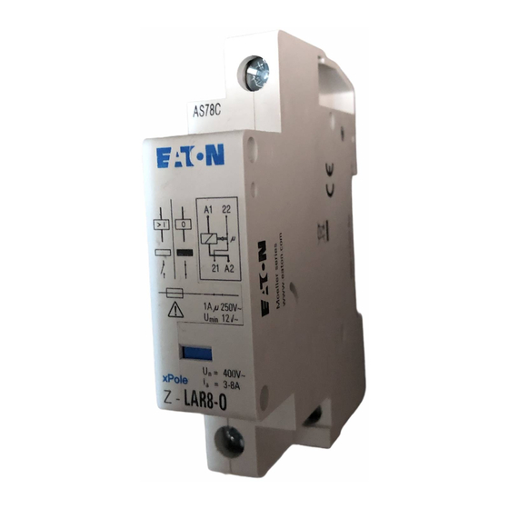
Load Control Relay Z-LAR
1. Description and Function:
Current relay with auxiliary switch output for detecting the electrical operating status of power consumers. This product is also known
as priority switch or current indicator.
Within the rated current range specifi ed, the device is used primarily to indicate current ON and OFF status, conditionally suitable
for rising currents. Fast current rise required. A internal mechanical spring switch (auxiliary contact) helps to prevent undefi ned
switching status.
The operating current to be monitored is routed with low power loss via the main terminals A1 - A2 of the relay. The auxiliary switch - make
contact, break contact or change-over contact - is connected to the other two terminals. Auxiliary switch output of make contact and
break contact types are potential-free and surge voltage proof against the main circuit. The change-over contact type has an internal
connection to the main circuit in order to permit the change-over function with the two terminals available at a width of 1 module unit only.
The effect of the switching operation activated by the fl ow of current on the auxiliary switch is instantaneous. The auxiliary switch
is low voltage proof, and consequently can be used to control electronic circuits too. Take into account the maximum current load
and back-up fuse according to item 4.
2. Indicator:
A mechanical current indicator changes between the colours white and blue depending on whether the relay coil is energised or in
quiescent state. The reference explanation regarding the conversion of indicator information to the auxiliary switch status is clearly
shown on the label printed onto the device.
3. Installation:
The relay has been designed for installation on DIN rails and can be used at an ambient temperature of up to 40
can be combined into blocks. It is suitable for phases and auxiliary circuits comming from different main systems. At high ambient
temperatures, and when approaching the limits of the rated current range it is important to provide for suffi cient heat dissipation,
e.g. by installing spacers.
NC
NO
4. Electrical Data:
Rated peak withstand voltage
Rated insulation voltage
Maximum operating voltage
Rated operating current (max. constant thermal current)
Power loss at rated operating current
Responding current, typically at
Release current, typically at
Switching delay
Maximum permissible back-up fuse (short circuit)
Ambient temperature range
Auxiliary Switch
Rated operating voltage
Rated operating current
Minimum operating voltage
Max. permissible back-up fuse
Conditional short circuit current
Instruction Leaflet
Montageanweisung
Notice d'installation
Instrucciones de montaje
Istruzioni per il montaggio
Инструкция по монтажу
Montagehandleiding
Lastabwurf- (Strom)-Relais Z-LAR
1. Beschreibung und Funktion:
Stromrelais mit Hilfsschalter-Ausgang zum Erkennen elektrischer Betriebszuständen von Stromverbrauchseinrichtungen. Weitere
gebräuchliche Produktbezeichnungen: Vorrangschalter, Stromwächter.
Im angegebenen Strom-Arbeitsbereich hauptsächlich zum Melden von Strom EIN- und AUS-Zuständen, bedingt für ansteigende
Ströme geeignet. Zügiger Stromanstieg erforderlich. Mechanischer Kippschalter (Hilfskontakt) vermeidet undefi nierten Schaltzustand.
Der zu überwachende Strom wird verlustarm über die Haupt-Klemmen A1-A2 des Relais geführt. An den beiden anderen Klemmen
liegt der Hilfsschalter-Öffner, Schließer oder Wechsler. Hilfsschalterausgang der Schließer- und Öffner-Typen sind potentialfrei und
stoßspannungsfest gegenüber der Hauptstrombahn. Beim Wechsler besteht eine interne, elektrische Verbindung zur Hauptstrombahn.
Der durch Stromfl uss aktivierte Schaltvorgang wirkt unverzögert auf den Hilfsschalter. Dieser ist kleinspannungstauglich, also auch
zum Ansteuern von elektronischen Schaltkreisen geeignet. Maximale Strombelastung und Vorsicherung gemäß Pkt. 4 beachten.
2. Anzeige:
Eine mechanische Stromanzeige wechselt zwischen den Farben Weiß und Blau, wenn die Relaisspule stromdurchfl ossen oder im
Ruhezustand ist. Die Übersetzung der Anzeige auf den Schaltzustand des Hilfsschalters ist im Geräteaufdruck eindeutig dargestellt.
3. Montage:
Das Relais ist zur Montage auf DIN-Schienen vorgesehen und kann bei Umgebungstemperaturen bis 40
Blockbauweise und an unterschiedlichen Stromsystemen -Außenleiter, Haupt-/Hilfsstromkreis - eingesetzt werden. Bei höheren
Umgebungstemperaturen und voller Ausnutzung des Arbeitsstrombereiches ist z.B. durch den Einbau von Distanzstücken auf
ausrechende Wärmeabgabemöglichkeit zu achten.
Ö
S
4. Elektrische Daten:
Bemessungs-Stoßspannungsfestigkeit
Bemessungs-Isolationsspannung
Betriebsspannung max.
Bemessungsbetriebsstrom = max. therm. Dauerstrom
Verlustleistung bei Bemessungsbetriebsstrom
Ansprechstrom typisch bei
Rückfallstrom typisch bei
Schaltverzögerung
Max. zulässige Vorsicherung (KS)
Zulässige Umgebungstemperatur
Hilfsschalter
Bemessungsbetriebsspannung
Bemessungsbetriebsstrom
Mindest-Betriebsspannung
Max. zulässige Vorsicherung
Bed. Kurzschlussstrom
Montagevejledning
Montāžas instrukcija
Kullanma Talimatı
Οδηγίες εγκατάστασης
Montavimo instrukcija
Инструкција за монтажу
Instruções de montagem
Instrukcja montażu
Intruksjonsblad
Monteringsanvisning
Navodila za montažo
Монтажна інструкція
تª ø¥u¤ة اL[ 
Asennusohje
Návod na montáž
Návod k montáži
Монтажни инструкции
Paigaldusjuhend
Instrucţiuni de montaj
Szerelési utasítás
Upute za montažu
GB
C. Several units
O
CO
4000 V AC
440 V AC
250 V AC
8 / 16 / 32 A
3.4 / 2.0 / 3.2 W
> 3 / > 10 / > 15 A
< 1.8 / < 4.2 / < 7.4 A
none
100 A gL
-5
C to +40
C
0
0
250 V
1A (μ)
12 V (300 mW)
10 A gL
1000 A
Montagevejledning
Montāžas instrukcija
Kullanma Talimatı
Οδηγίες εγκατάστασης
Montavimo instrukcija
Инструкција за монтажу
Instruções de montagem
Instrukcja montażu
Intruksjonsblad
Monteringsanvisning
Navodila za montažo
Монтажна інструкція
تª ø¥u¤ة اL[ 
Asennusohje
Návod na montáž
Návod k montáži
Монтажни инструкции
Paigaldusjuhend
Instrucţiuni de montaj
Szerelési utasítás
Upute za montažu
D
0
C auch mehrfach in
W
4000 V AC
440 V AC
250 V AC
8 / 16 / 32 A
3,4 / 2,0 / 3,2 W
> 3 / > 10 / > 15 A
< 1,8 / < 4,2 / < 7,4 A
keine
100 A gL
-5
C bis +40
C
0
0
250 V
1A (μ)
12 V (300 mW)
10 A gL
1000 A
5. Mechanical Characteristics
Terminal capacity, auxiliary switch
Terminal capacity, main circuit
Type of terminals
Terminal screws
Terminal torque, main circuit
Terminal torque, auxiliary switch
Max. switching frequency
Electrical endurance
6. Applications:
The current relay Z-LAR permits to give important equipment or plant components in consumer systems operating priority over
less important consumers. Heating devices and water heaters can be submitted to automatic staggering of functioning periods.
In this way, expensive power consumption during peak hours is avoided in a secure, simple, and cost-effi cient way. This helps
to honour tariff agreements.
The device can also be used as a current indicator for operating status messages, as well as for oposite electrical interlocking
of devices. The low working current range permits monitoring of small motors, pumps, and fans. The main circuit is short circuit
proof.
Electrical combining of auxiliary switch output permits a logic AND/OR function of an operating program. This is achieved on
the smallest mounting space possible, using conventional wiring techniques, and within the shape compatible switching device
range.
Example
Example
Priority pump
Logic "OR"-function
e.g.
Heater
pump
7. Important notes:
This relay has to be installed by a technical qualifi ed and authorized electrician according to the legal regulati-
ons. If it does not work despite correct installation, the device may be damaged and has to be returned to the
manufacturer. Any repairs or interventions by the customer are forbidden! Enclosed label must be fi xed visible!
Eaton Industries (Austria) GmbH, Eugenia 1, 3943 Schrems, Austria
© 2018 by Eaton Industries (Austria) GmbH, www.eaton.eu/documentation
5. Mechanische Eigenschaften:
Klemmenquerschnitt Hilfsschalter
Klemmenquerschnitt Hauptstrom
Klemmentyp
Klemmenschrauben
Klemmendrehmoment Hauptstrom
Klemmendrehmoment Hilfsschalter
Max. Schalthäufi gkeit
Elektrische Lebensdauer
6. Anwendungen:
Mit Hilfe des Stromrelais Z-LAR ist es möglich, in Verbraucheranlagen wichtigen Geräten oder Anlagenteilen Betriebsvorrang
gegenüber weniger wichtigen Verbrauchern zu geben. Automatisch können Heiz- oder Warmwassergeräte einer Funktionsstaf-
felung zugeordnet werden, teure Stromverbrauchsspitzen werden sicher, einfach und damit preiswert vermieden. Die Einhaltung
von Tarifvereinbarungen ist somit sichergestellt.
Als "Stromwächter" sind Stromfl uss-und damit Betriebszustands-Meldungen ebenso möglich, wie gegenseitige, elektrische
Verriegelungen von Geräten. Ein niedriger Arbeitsstrombereich ermöglicht auch das Überwachen von kleinen Motoren, Pumpen
und Ventilatoren. Die Hauptstrombahn ist kurzschlussfest.
Durch elektrische Verknüpfung der Hilfsschalter-Ausgänge ist eine logische UND-/ODER- Funktion eines Betriebsprogrammes
möglich, Dies auf kleinstem Montageraum, in konventioneller Verdrahtungstechnik und im konturkompatiblen Schaltgeräte-
Programm.
Schaltbeispiel
Vorrang Pumpe
"ODER"-Verknüpfung, Absaugung
7. Hinweise:
Die Montage, der Anschluss und die Inbetriebnahme dieses Gerätes darf nur durch eine autorisierte Elektrofachkraft erfolgen. Wird
trotz Beachtung der Montagehinweise keine einwandfreie Funktion des Gerätes erreicht, kann dieses schadhaft sein und ist an den
Hersteller einzusenden. Eigene Eingriffe in den Schalter sind nicht zulässig und schließen jede Gewährleistung aus!
Eaton Industries (Austria) GmbH, Eugenia 1, 3943 Schrems, Austria
© 2018 by Eaton Industries (Austria) GmbH, www.eaton.eu/documentation
1 x 1 to 2 x 2,5 mm² max.
1 x 1 to 2 x 10 mm² max.
Lift terminals
Captive screws, Pozidrive No. 2
max. 2,4 Nm
max. 1.0 Nm
3600 operations per hour
100.000 switching operations
Example
Operation state
e.g.
Fan
MA-Z-lar8-off.indd / 09.2019e / IL019154ZU / 150501263
www.eaton.com/recycling
All Rights Reserved / Printed in Austria
1 x 1 bis 2 x 2,5 mm² max.
1 x 1 bis 2 x 10 mm² max.
Liftklemme
Pozidrive Nr. 2, unverlierbar
2,4 Nm max.
1,0 Nm max.
3600 / h
100.000 Schltg.
Schaltbeispiel
Schaltbeispiel
Betriebszustand
MA-Z-lar8-off.indd / 09.2019e / IL019154ZU / 150501263
www.eaton.com/recycling
All Rights Reserved / Printed in Austria
e.g.
Z-L/RG
Motor
ON
Motor
OFF
z.B.
Z-L/RG
Motor
EIN
Motor
HALT
Werbung

Verwandte Anleitungen für Eaton Z-LAR


Inhaltszusammenfassung für Eaton Z-LAR
- Seite 1 1. Description and Function: The current relay Z-LAR permits to give important equipment or plant components in consumer systems operating priority over Current relay with auxiliary switch output for detecting the electrical operating status of power consumers. This product is also known less important consumers.
- Seite 2 V určitém rozsahu jmenovitého proudu lze Proudové relé Z-LAR umožňuje dát důležitým zařízením nebo částem podniků v systémech zařízení používat hlavně pro indikaci stavů ON (ZAP) a OFF (VYP), podmíněně je vhodné pro vzestupné...