PowerWalker VFI 6000 CG PF1 Bedienungsanleitung
Vorschau ausblenden
Andere Handbücher für VFI 6000 CG PF1:
- Kurzanleitung (8 Seiten) ,
- Bedienungsanleitung (35 Seiten) ,
- Bedienungsanleitung (60 Seiten)

Verwandte Anleitungen für PowerWalker VFI 6000 CG PF1


Inhaltszusammenfassung für PowerWalker VFI 6000 CG PF1
- Seite 1 Pow erWalker VFI 6000 CG PF1 VFI 10000 CG PF1 User Manual EN / DE Version: 1.1 Downloaded from www.Manualslib.com manuals search engine...
- Seite 30 Pow erWalker VFI 6000 CG PF1 VFI 10000 CG PF1 Bedienungsanleitung Version: 1.1 Downloaded from www.Manualslib.com manuals search engine...
- Seite 31 Alle Warnungen und Bedienungshinw eise in dieser Anleitung müssen unbedingt beachtet w erden. Bew ahren sie diese Anleitung gut auf und lesen Sie die folgenden Hinw eise vor der I nstallation sorgfältig durch. Nehmen Sie das Gerät erst Betrieb, w enn alle Sicherheitshinw eise Bedienungsanleitung...
- Seite 32 I nhaltsverzeichnis 1. SI CHERHEI T UND EMV-HI NWEI SE ........................1 1-1. TRANSPORT UND LAGERUNG ..........................1 ................................1 1-2. V ORBEREI TUNG 1-3. I ................................1 NSTALLATI ON 1-4..........................2 NSCHLUSS WARNHINWEISE 1-5. B ..................................3 ETRI EB 1-6.
-
Seite 33: Si Cherhei T Und Emv-Hi Nwei Se
1. Sicherheits- und EMC Hinw eise Bitte lesen Sie die folgenden Sicherheitshinweise und die Bedienungsanleitung vor der I nstallation und Erstbenutzung aufmerksam durch! 1-1. Transport und Lagerung Bitte transportieren Sie das USV-System nur in der Originalverpackung, um es vor Schlägen und Stößen zu schützen. -
Seite 34: Anschluss Warnhinweise
1-4. Anschluss Warnhinw eise • I nnerhalb gibt es keinen Standard-Nachspeiseschutz, bitte isolieren Sie die USV vor dem Betrieb entsprechend. Die Trennvorrichtung muss in der Lage sein, den USV-Eingangsstrom zu führen. Diagramm 1: Externe Nachspeise-Schutzverdrahtung • Diese USV sollte an ein TN Erdungssystem angeschlossen werden. •... -
Seite 35: Standards
1-5. Operation Das Erdungskabel während des Betriebs nicht von der USV-Anlage abziehen, da sonst die Schutzerdung der USV-Anlage und aller angeschlossenen Verbraucher aufgehoben wird. Das USV-System verfügt über eine eigene, interne Stromquelle (Batterien). Die USV -Ausgangssteckdosen oder Ausgangsklemmen können stromführend sein, auch wenn die USV nicht an die Steckdose bzw. -
Seite 36: I Nstallation Und Betrieb
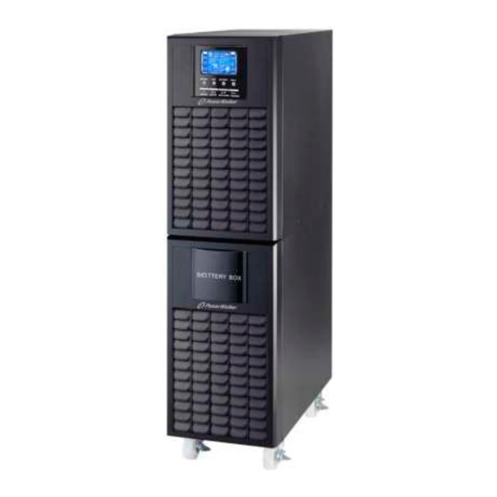
2. I nstallation und Betrieb Es gibt zwei unterschiedliche Arten von Online-USV: Standard und Long-run Modelle. Bitte beachten Sie folgende Modellübersicht. Modell Modell Long-run Standardmodell 10KL Modell Optional bieten wir auf Anfrage für diese Typen auch eine “Parallel-Funktion” an. Die USV mit Parallel-Funktion wird “Parallel-Modell ”... -
Seite 37: Usv Einzelinstallation
2-3. USV Einzelinstallation Die I nstallation und Verdrahtung ist gemäß den geltenden Bestimmungen unter Beachtung der örtlichen Vorschriften von einem Fachmann durchzuführen. 1) Stellen Sie sicher, dass die Nennleistung des Netzkabels und der Schalter ausreichend sind, um Stromschlägen und Brandgefahr vorzubeugen. HI NWEI S: Schließen Sie die USV nicht an die Wandsteckdose an, wenn die Nennleistung geringer ist, als der maximale Eingangsstrom der USV. - Seite 38 WARNUNG: (nur für das Standardmodell) ● Stellen Sie sicher, dass. Die USV vor der I nstallation ausgeschaltet ist. Die USV sollte während der Verdrahtung nicht eingeschaltet werden. ● Versuchen Sie nicht ein Standard-Modell in ein Long-run-Modell zu verändern. Versuchen Sie nicht die eingebaute Batterie an eine externe Batterie anzuschließen.
-
Seite 39: Software Installati On
6) Beachten Sie folgenden Schaltplan: Diagramm 1: Netzkabelanschluss Diagramm 2: Anschlussdiagramm für das Parallel-System 2-5. Softw are I nstallation Für einen optimalen Computersystemschutz, installieren Sie die USV Überwachungssoftware, um das Abschalten der USV programmieren zu können. Downloaded from www.Manualslib.com manuals search engine... -
Seite 40: Betrieb
3. Betrieb 3-1. Tastenbedienung Taste Funktion Anschalten der USV: Drücken und halten Sie die Taste für mindesten 0.5 Sekunden, um die USV einzuschalten . ON/ ENTER-Taste Enter Taste: Dr ü cken Sie diese Taste um die vorangegangene ä Auswahloptionen in den USV Einstellungen zu best tigen . - Seite 41 LCD Panel: Anzeige Funktion Backup-Zeitinformation Zeigt die Batterieentladezeit in Zahlen H: Stunden, M: Minuten, S: Sekunden Fehlerinformation Zeigt Warnungen und Fehler an. Zeigt die Fehlerkodierung, und die Kodes wie in Abschnitt 3-9 beschrieben. Stummschaltung Zeigt an, dass der USV-Alarm ausgeschaltet ist. Ausgangs- und Akkuspannung Zeigt die Ausgangsspannung, Frequenz oder Akkuspannung an.
-
Seite 42: Akustischer Alarm
Zeigt den Ladungszustand des Akkus in 0-25% , 26-50% , 51-75% , und 76-100% an. Zeigt an, dass der Akku nicht angeschlossen ist. Zeigt einen niedrigen Ladezustand und Spannung des Akkus an. Eingangs- & Akkuspannung I nformation Zeigt die Eingangsspannung oder -frequenz oder die Akkuspannung an. Vac: Eingangsspannung, Vdc: Akkuspannung, Hz: Eingangsfrequenz 3-3. - Seite 43 Betriebsmodus. Nach der I nitialisierung wechselt die USV in den kein Eingabemodus. Drücken und halten Sie die „ON“ Taste an der USV für mindestens 0.5 Sekunden bis die USV einschaltet und der Akustischer Warnton einmal piept. Nach einigen Sekunden schaltet die USV ein und wechselt in den Akkubetrieb. 3-4-3.
- Seite 44 Entladung 16,5 Stunden, schaltet die USV zum Schutz des Akkus automatisch ab. Dieser Batterieentladungsschutz kann aktiviert oder über die LCD-Panel Steuerung deaktiviert sein. (Siehe 3-7 LCD-Einstellungsabschnitt) 3-4-6. Batterie testen Wenn Sie während des Netzbetriebes / CVCF Modus den Batteriestatus überprüfen möchten, drücken Sie die “Test”...
- Seite 45 überprüfen Sie die WARNUNGEN 3-11 der Codetabelle und die Hinweise im Kapitel 4 Fehlerbehandlung. Nachdem der Fehler auftritt überprüfen Sie bitte die Lasten, Verdrahtung, Lüftung, Programme und Batterie. Schalten Sie die USV nicht ein, bevor die Probleme gelöst sind. Wenn die Probleme nicht behoben werden können, wenden Sie sich bitte unverzüglich an den Händler oder den Kundendienst.
-
Seite 46: Parallelbetrieb
USV ausschalten. Kann die Last nicht unterbrochen werden, entfernen Sie die Abdeckung auf der Rückseite und stellen Sie zuerst den Wartungsschalter in die “BPS” Position. Schalten Sie den Eingangsschalter und den Batterieschalter aus (nur für Long-run Modelle verfügbar). Entfernen Sie die Gehäuseabdeckung und trennen Sie das Batteriekabel des Standard-Modells. Dann ändern Sie den Jumper (Drahtbrücke) auf der Steuerplatine, um die Batterieanzahl zu wählen, wie in folgender Tabelle dargestellt. -
Seite 47: Abkürzung Bedeutung Der Lcd-Anzeige
USV anschalten. Nach einigen Sekunden wechselt die USV in den Batteriebetrieb. Drücken Sie die “ON” Taste, um die Stromversorgung für eine weitere USV einzurichten, überprüfen Sie, ob PARXXX angezeigt wird. Falls nicht, bitte überprüfen Sie, ob die Parallel-Kabel richtig angeschlossen sind. c) Dann eine andere USV anschalten. - Seite 48 Aktivieren DI S Deaktivieren Auto Batterie Standardbetrieb (nicht CVCF Modus) CVCF Modus Subtract Unzulässig Zulässig Vorbehaltlich OP .V Ausgangsspannung Parallel Downloaded from www.Manualslib.com manuals search engine...
-
Seite 49: Lcd Einstellung
3-7. LCD Einstellung Es können drei Parameter eingestellt werden. Siehe folgendes Diagramm. Parameter 1 Parameter 1: I st für ein alternatives Programm. Es gibt 16 Programme. Siehe Tabelle unten. Parameter 2 und Parameter 3 geben die Einstelloptionen oder Werte für jedes Programm wieder. - Seite 50 Parameter 3: Ausgangsspannung Sie können folgende Ausgangsspannungen in Parameter 3 wählen: 208: Ausgangsspannung 208V Wechselstrom 220: Ausgangsspannung 220V Wechselstrom 230: Ausgangsspannung 230V Wechselstrom 240: Ausgangsspannung 240V Wechselstrom 02: Ausgangsfrequenz Schnittstelle Einstellung Parameter 2: Ausgangsfrequenz Sie können folgende drei Einstellung der Ausgangsfrequenz. Optionen in Parameter 2 wählen 60 Hz, CVCF Mode 50.0Hz:...
- Seite 51 Schnittstelle Einstellung Parameter 2: Stellen Sie die tolerable Höchst- und Niedrigspannung für den Bypass-Modus ein . Einstellungsbereich von 110V bis 209V und der Standardwert liegt bei 110V. Parameter 3: Stellen Sie die tolerable Höchst- und Niedrigspannung für den Bypass-Modus ein . Einstellungsbereich von 231V bis 276V und der Standardwert liegt bei 264V.
- Seite 52 Schnittstelle Einstellung Parameter 2: : Bypass zulässig. Wenn ausgewählt, läuft die USV über den Bypass-Modus, je nachdem ob dieser aktiviert oder deaktiviert ist. : Bypass ist nicht zulässig. Wenn ausgewählt, ist der Bypass-Modus nicht zulässig. Parameter 3: : Bypass aktiviert. Wenn ausgewählt, ist der Bypass-Modus aktiviert.
- Seite 53 13: Batteriespannungsanpassung Schnittstelle Einstellung Parameter 2: Wählen Sie “ ” oder “ ” um die Batteriespannung einzustellen. Parameter 3: Der Spannungsbereich ist von 0V bis 5.7V und der Standardwert liegt bei 0V. 14: Ladegerät Spannungsanpassung Schnittstelle Einstellung Parameter 2: Sie können mit oder die Ladespannung...
- Seite 54 15: I nverter Spannungsanpassung Schnittstelle Einstellung Parameter 2: Sie können mit oder die Spannung des I nverters einstellen. Parameter 3: Der Spannungsbereich ist von 0V bis 6.4V und der Standardwert liegt bei 0V. 16: Ausgangsspannung Kalibrierung Schnittstelle Einstellung Wenn die Ausgangsspannung nicht erkannt werden kann (weniger als 50VAC), wird dieses Menü...
- Seite 55 ECO Modus Beschreibung Die USV leitet die Spannung direkt zum Ausgang, wenn sich die Eingangsspannung im akzeptablen Bereich liegt, um Energie zu sparen. LCD-Anzeige CVCF Modus Beschreibung Wenn die Eingangsfrequenz innerhalb 46 to 64Hz ist, kann die USV auf eine konstante Ausgangsfrequenz von 50Hz oder 60Hz eingestellt werden.
-
Seite 56: Fehlercode
LCD-Anzeige Fehlerstatus Beschreibung Wenn Fehler in der USV auftreten, wird eine Fehlermeldung im LCD-Panel angezeigt. LCD-Anzeige 3-9. Fehlercode Fehlerereignis Fehlercode Symbol Fehlerereignis Fehlercode Symbol Busstartfehler Keines Batterie SCR Kurzschluss Keines Inverter-Relais Bus über Keines Keines kurzgeschlossen Bus unter Keines Ladegerät Keines kurzgeschlossen Bus unausgeglichen... -
Seite 57: Warncode
Ertönt jede Sekunde Lüfterfehler/ Übertemperatur Ertönt jede Sekunde Ladefehler Ertönt jede Sekunde I / P Sicherung defekt Ertönt jede Sekunde Überlastung 3 Mal in 30 Min. 3-11 Warncode Warncode Warnereignis Warncode Warnereignis Batterie nicht angeschlossen L1 I P Sicherung defekt Leitungsposition im Parallel-System Überlastung unterschiedlich... -
Seite 58: Fehlerbehebung
4. Fehlerbehebung Falls die USV nicht einwandfrei funktioniert, können Sie den Fehler mit Hilfe der Tabelle unten beheben. Mögliche Ursache Abhilfe Symptom Keine Anzeige Alarm Überprüfen Sie, AC-Eingangsleistung Displayfeld, obwohl das Netz normal Eingangskabel fest an das Netz nicht gut verbunden. ist. -
Seite 59: Lagerung Und I Nstandhaltung
5. Lagerung und I nstandhaltung 5-1. Lagerung Laden Sie die USV für 7 Stunden. Lagern Sie die USV abgedeckt und aufrecht in einem kühlen und trocken Ort. Laden Sie die Akkus gemäß folgender Tabelle: Lagertemperatur Ladungshäufigkeit Ladezeit Alle 3 Monate -25°C - 40°C 1-2 hours Alle 2 Monate... -
Seite 60: Spezifikationen
6. Spezifikationen MODELL VFI 6000 CG PF1 VFI 10000 CG PF1 KAPAZI TÄT* 6000 VA / 6000 W 10000 VA / 10000 W I NPUT 110~ 300Vac @ (0~ 60% ) Last Niedrige Überleitung 140~ 300V @ (60~ 80% ) Last...