Herunterladen Inhalt Inhalt Diese Seite drucken
Inhaltsverzeichnis

Werbung

Verfügbare Sprachen

Verfügbare Sprachen

Leica DM2000
Leica DM2500
Leica DM3000
操作手册

Werbung

Inhaltsverzeichnis
loading

Inhaltszusammenfassung für Leica DM2000

  • Seite 1 Leica DM2000 Leica DM2500 Leica DM3000 操作手册...
  • Seite 2 2005 五月由:  Leica 微系统 wetzlar 有限公司  Ernst­Leitz­Straβe  D­35578 Wetzlar (德国) 出版发行。 编撰负责人:  Jasna Röth Peter Schmitt  博士 (临床显微镜检查、产品管理)  Holger Grasse  ( MPG § 30 安全员 )  如有疑问,请致热线: 电话:  +49 ( 0 ) 6441 292286  传真:  +49 ( 0 ) 6441 ­ 292255  电子邮件:  MQM­Hotline@_leica­microsystems. ...
  • Seite 3 Leica DM2000 Leica DM2500 Leica DM3000 操作手册...
  • Seite 4 版权 版权 此文献的所有权利归 leica 微系统 wetzlar 有限公司 所有。 在未经 Leica 微系统 Wetzlar 有限公司明确的书 面允许情况下,不允许通过打印 , 影印 , 显微胶片或其 他方法(包括电子系统 ) 对正文或插图进行拷贝。 在以下文献中的说明体现了最新的技术和学科标 准。我们尽可能精确地编撰了正文和插图。尽管如 此, 我们对手册内容的准确性不负任何种类的责任。 但是,我们仍然感激有关此文献中潜在错误的评论 和建议。 此手册中的信息可能会随时并且在没有通知的情况下 有所修改。...
  • Seite 5: Inhaltsverzeichnis

    目录  目录 1. 有关手册的重要注解  ... ... .. .. ... ...    ... ...  6 8.5 目镜 ... ........... ... ... .. ... ... 47  8.6 物镜  ..............48  2 . 显微镜的目标用途  ... ... ... ... ... .. .. .. ... 7 8.7 Leica DM3000 功能键  ...... ... ... 49  8.8  光源  ... ............52  3 . 安全备忘录  ... ... ... ... ... ... . .. .. .. .. ... ...  8  8.9  孔径光圈  ... .............53  3.1  一般安全备忘录  .......... 8  8.10  视野光圈  ... ............54  3.2  用电安全  ............ 8 ...
  • Seite 6: 有关手册的重要注解

    ⒈有关手册的重要注解 ⒈有关手册的重要注解 注意 !  此操作手册包含了有关显微镜及其附件操作安全和 此操作手册是显微镜至关重要的组成部分,在 维护方面的重要说明和信息。因此,该手册必须保 显微镜组装好,开始操作或者使用以前必须仔 存好并妥善保管。 细地阅读。 正文 中的 符号,象 形图 和它 们的 寓意 :  (1.2)  括号中的数字,比如 " ( 1.2 ) " 与插图相对应(在该 例子,对应于图1、条款2)。 带有指示箭头的数字(例如 ® p.  ® p . 20 ),表示在此手册的某一页。 注意 !  手册中的特别安全说明用如这里所显示的三 角形符号表示,且有灰色背景。 注意 ! 操作不正确可能损坏显微镜及其附件。 解释性说明。 ...
  • Seite 7: 显微镜的目标用途

    ⒉显微镜的目标用途 ⒉显微镜的目标用途 此用户手册适用于被设计用于生物学常规和研究应 注意 !  用的 Leica DM2000 、 DM2500 和 DM3000 显微镜。其 中包括对从人体取下的样本进行检查以便提供有关 厂家对由于使用显微镜用于它们的目标用途以 生理或病理状态或先天异常的信息,或测定潜在受 外的其他用途或者没有在 Leica 微系统 Wetzlar  体的安全性和兼容性,或监控治疗方法。 有限公司 GmbH 的技术规范下使用它们而造成 的损坏不负任何责任。 上述提到的所有显微镜遵照关于活体外诊断的委 在上述情况出现时,合格声明将不再有效。 员会指示 98/79/EEC 。它们同时也符合用于工业环 境的有关电子仪器的委员会指令 73 / 23 / EEC 和 有关电磁兼容性的委员会指令 89/336/EEC 。 注意 ! ...
  • Seite 8: 安全备忘录

    最大值: 80% to 30 ° C  II  周围温度: 注意 !  相对湿度: 2  为了保持此状态并且确保安全操作,用户须遵 过电压种类: 守此操作手册的指导和警告。  污染级别:  注意 !  注意 !  电源插头只能插入到有接地触头的插座。 在此操作手册描述的仪器和附件都已经通过安 全和潜在危险测试。 无论何时当仪器被改变、修正或与在此手册范 不要由于使用没有接地线的延长电线而妨碍接 围之外的非 Leica 组件相连接时,必须咨询负责 地功能。 仪器内部或外部任何接地线的断开, 的 Leica 分支机构或在德国 Wetzlar 的总厂。 或接地线接头脱扣,都可能导致仪器出现危 险。 不许故意断开接地线 !  未经批准的对仪器的变更或非顺从使用,将使 全部有关保证声明的权利作废 ! ...
  • Seite 9 ⒊安全备忘录 注意 !  注意 !  通过把它们自身的和 / 或额外的供给电源连接到 保护显微镜避免过大的温度波动。 大的温度波 接地连接附属设备(在基座的背后的接地螺 动可能导致冷凝物的积聚,这可能损坏电子和 丝) ,仪器会具有相同的接地线功效。要进行没 光学部件。 有接地接头的连接,必须事先向 Leica 服务部门 ℃ 周围温度: 15 - 35 。 咨询。 注意 !  注意 !  在更换保险丝或灯炮之前,要百分之百地确定 除这里所列的类型和额定电流的保险丝外,决 已经关掉主电源开关并且拔掉电力电缆。 不能使用其他任何保险丝作为替代物。不许使 用由小段连接成的保险丝或桥接保险丝夹持 器。保险丝使用不正确可能导致火灾。 注意 !  显微镜的电子附属部件是不防水的。 水可能导 致触电。 ...
  • Seite 10: 仪器概观

    4. 仪器概观 4.仪器概观 规格  Leica DM2000  Leica DM2500  对照方法  •  透射光:明视野、暗视场、位相衬度、偏光、差别干涉相衬 • 入射光:荧光 灯室 透射光轴 综合卤素照明 人工调节: 人工调节: • 光线强度 • 光线强度 • 孔径光圈 • 孔径光圈 • 视野光圈 • 视野光圈 入射光轴 入射的光荧光发光器,用于符合目镜视野值 22 带有: • 具有5个过滤器的旋转台转盘 • 可中心定位的光圈和视野光圈 • 用于外部光线抑制的挡光装置 •  N4 中性密度滤光片和快门 , 可切换...
  • Seite 11 4. 仪器概观 规格 Leica DM2000  Leica DM2500  •  聚光器  CL / PH 0.90 / 1.25 , 油,带有彩色编码 聚光器  (所带物镜 <10x 的 DM2500 需要扩散器滑动器) •聚光器 CLP / PH 0.85 用于偏光  ( 所带物镜 <10x 的 DM2500 需要扩散器滑动器) •聚光器 achr.apl.  A  0.9 ( P) 带有彩色编码和可旋转的聚光器头部 • UCL 0.90 / 1.25 油性通用聚光器( UCLP 0.85 用于带有 5 位光圈转...
  • Seite 12 4. 仪器概观 规格 Leica DM3000  • 透射光:明视野、暗视场、位相衬度、偏光、差别干涉相衬 对照方法  • 入射光:荧光 透射光轴 内置卤素照明 人工调节: • 孔径光圈 • 视野光圈 • 随着对象改变的光线强度的自动调节 入射光轴 入射的光荧光发光器,用于符合目镜视野值 22 带有: • 具有5个过滤器的旋转台转盘 • 可中心定位的光圈和视野光圈 • 用于外部光线抑制的挡光装置 •  N4 中性密度滤光片和快门 , 可切换 镜筒 选择性地带有: • 固定或可变观察角 • 多达3个的切换位置 • 一个或两个照相端口...
  • Seite 13 • 聚光器 CLP / PH 0.85 用于偏光 • 聚光器 achr.apl 。  A 0.9 ( P) 带有可旋转聚光器头部 •  UCL / P pol, 带有可互换聚光器头部的通用聚光器和带有6个位置 的聚光器转盘。 •机动化聚光器 achr.apl.A0.9(p) ,自动 物镜更换时,聚光器头部自动旋转 • 用于粗略和精确调焦的聚焦操纵轮 聚焦 • 高度调节 • 快速切换(可选择) • 聚焦制动和转矩调节 界面  USB2  软件 适合于 WindowsTM 2000, XP 的 leica 应用套装( LAS )用于 物镜和功能键配置的测试 ...
  • Seite 14 4. 仪器概观  7  6  5  4  1  2  3  图 . 1a  Leica DM2000 基座左侧面  1  粗略调焦和精确调焦 2聚光器高度调节 3亮度控制 4视野光圈 5孔径光圈 6聚光器 7分析器长眼 ...
  • Seite 15 4. 仪器概观  1  2  3  4  5  6  8  9  10  11  7  图 . 1b  Leica DM2000 基座的右侧面  1 目镜 2目镜筒 3镜筒 4用于物镜棱镜滑座的长眼 5带有物镜的物镜旋转台 6带有样品夹的样品载物台 7内置照明  8 “开/关”开关 9聚光器高度调节  10 粗略调焦和精确调焦  11 用于X/ y 载物台运动的同轴小齿轮 ...
  • Seite 16 14  13  12  11  10  9  8  1  2  3  4  5  6  7  图 . 2  Leica DM2500 基座的左侧面  10  聚光器转盘  1  灯室  11  聚光器  2  粗略调焦和精确调焦  12  带有样品夹的样品载物台  3  亮度控制  13  带有物镜的物镜旋转台  4  聚光器高度调节  14  物镜棱镜滑座  5  视野光圈调节  15  镜筒 ...
  • Seite 17 2  3  4  5  6  13  8  12  7  9  10  11  图 . 3  Leica DM3000 基座的右侧面  1 目镜 11 用于X/ Y 载物台运动的同轴小齿轮  2目镜筒 12  带有物镜转换键和切换键前控制面板  3镜筒 13  用于在两个物镜放大倍数之间转换或用于切换放大倍数 ( 大 4用于物镜棱镜滑动器的长眼 5带有物镜的物镜旋转台 的/较小 ) 的侧功能键 6带有样品夹的样品载物台 基座 analog 的左侧 7内置照明...
  • Seite 18: 启封显微镜

    ⒌启封显微镜 ⒌启封显微镜 安装位置 首先,小心的从运输和包装物中取出所有组件。 使用显微镜的工作应在无尘的房间内进行, 且该房间 无油蒸汽及其他化学制剂蒸汽, 另外不处于极端的湿 度。 在工作地点,应该避免大的温度变化、阳光 直接和振动。以上情况出现可能导致度量不准和显微 注意: 图像失真。 尽一切可能避免触及物镜的透镜表面。如果玻璃杯 表面有了手印,用软革或亚麻布清除它们。即使是 允许的周围条件 一点手汗也会在很短时间内损坏表面。 参见章节 “显 ℃ 温度:  15­35 微镜护理” ℃ 相对湿度:  30 以下最大值为 80%  ® p . 70 ,以获得补充说明。 在温暖的和温湿的气候带的显微镜需要额外的照料 以免真菌的滋生。 见章节“显微镜护理” ® p.  70 ,以获得补充说明。 注意...
  • Seite 19 ⒌启封显微镜 搬运 载运或搬运显微镜及其附件时, 应该使用其原包装。 作为预防由于振动而导致损坏的措施,以下组件应 该进行拆卸并分别地包装: • 拆卸下物镜。 • 取下聚光器。 • 取下同轴小齿轮。 • 取下灯室。 • 卸下 106 z 灯室的灯头。 • 取下所有移动或松动部件。 ...
  • Seite 20: 组装显微镜

    ⒍组装显微镜 ⒍组装显微镜 6.1 载物台 显微镜组件是按以下次序逻辑地组装的:  注意: • 载物台 • 聚光器 在安装好载物台之前,一定不要安装任何物镜 !  • 荧光 *  • 中间系统 *  • 镜筒 样品夹 • 目镜 • 物镜 • 把样品夹放置到载物台上并用两个螺丝钉 • 带有光源的灯室 ( 4.1 )把它拴紧。 • 偏光 *  只需要一个通常使用的螺丝刀就可以完成组装,且 同轴小齿轮 所递送物中包含有这种螺丝刀。 此螺丝刀保存在载物台下侧右边的磁性固定器上。 当使用中间系统和光学附件时,此次序可能有所变 注意:...
  • Seite 21 ⒍组装显微镜 •首先 , 把细调焦操纵轮放到你打算在其上固定同 轴小齿轮的一侧。 操纵轮由于磁性吸引而固定 住。要确保按钮发出劈啪声表示就位。把另一个 调焦旋钮缚到对侧。 • 松开载物台前面左手边的锁紧螺钉( 6.1 )。 • 尽可能远地向后滑动载物台。 • 用螺丝钉( 7.1 )固定同轴小齿轮。 • 向前拉载物台并重新固定锁定螺钉。 图 . 6  载物台下侧  1  锁定螺钉  1  图 . 5  聚焦操纵轮  图 . 7  同轴小齿轮的安装  1  用于细调焦操纵轮的磁性吸座 1  同轴小齿轮固定螺钉  1  1 ...
  • Seite 22: 聚光器

    • 拉聚光器的固定螺钉( 10.2 )锁定聚光器。  1  • 仅用于 leica dm3000 : 当使用机动化聚光器时,连接聚光器电缆。 图 . 10 聚光器座  1 聚光器中心定位 2聚光器固定螺钉  3 聚光器高度调整装置 图 . 8  聚光器下侧(例如 CL / PH )  1 方向销 2辅助聚光透镜 LS (用于 Leica DM2000 / 3000 )  1  1  3  3  2  1  1  2 ...
  • Seite 23: 镜筒和目镜

    仅用于 Leica DM3000 : 依照你的设备,各个物镜在工厂中就已经给定特定 • 将镜筒插入圆形塞孔中 的位置。 (楔形榫头塞环)。 物镜精确位置列表作为设备的一部分(鉴定单)提 供。前控制面板(图 . 1 2)的特征是有用于物镜操 • 重新固定固定螺钉( 11.1 )。  作的六个黑色键。标有相应物镜放大倍数的黏性标 签贴在物镜键的下面。  ( 还提供有额外的黏性标签 )  •  目镜要插入到镜筒上的目镜筒中。 推荐在与供给电源接通后再插入物镜 ® p  3 3)。 图 . 11 拴紧镜筒  1 固定螺钉 图 . 1 2  Leica DM3000 的前控制面板  1  选择物镜 反复切换 带有物镜放大倍数的黏性标签 ...
  • Seite 24: 光源 ­ 透射光轴

    插头和供给电源。 • 取下灯泡。 注意 !  注意 !  在你安装好灯泡以前不要撕下灯泡防尘罩。 避 光源有潜在的辐射危险(耀光、紫外射线、红 免在灯泡上留下指纹。 外线辐射)。因此,灯泡应在密闭的灯室内使 用。 •把带有防尘罩的新灯泡竖直地插入插座中直到 仅用于 Leica DM2000/3000 : 不能再向里面移动。 一定要确保灯泡是竖直插 入的。 更换内置照明的灯泡 带有低压卤钨灯的透射光照明(图 .  1 3)内置于显 •取下灯泡的防尘罩。 微镜的底部且从右手侧容易接近。 •更换衬垫( 13.2 ) .  图 . 1 3 显微镜座的透射光照明  图 . 14a  灯室 107 /2...
  • Seite 25 • 除去灯室上的固定器螺丝 ( 图 . 14a )。 •重新安装上灯室并利用固定螺钉把它固定到 位。 • 通过向上拉灯室把灯室卸下来。 •把灯室安装到透射光灯室塞孔里(图 .  1 5)并在 外面用固定螺钉拴紧。 • 取下灯泡。 注意 !  在你安装好灯泡以前不要撕下灯泡防尘罩。 避 免在灯泡上留下指纹。 图 . 1 5  Leica DM2500  1  用于透射光的灯室 图 . 14b  灯室 107 /2,打开图  1  带有卤素灯的底座  1  2  换向器  1  2 ...
  • Seite 26: 荧光发光器

    6.  组装显微镜  6.6 用于荧光操作的组件  把气体放电灯(汞和氙) 嵌入 106z 灯室中 6.6.1 荧光发光器 汞和氙灯泡由单独的供电装置供电。 荧光发光器安装在镜筒的前部。它由旁侧的固定螺 请阅读与供电设备一同提供的单独的使用说明书。  钉固定。 6.6.2 106z 灯室 注意 !  光源有潜在的辐射危险(耀光、紫外射线、红 图 . 16  荧光发光器的组装 外线辐射)。因此,灯泡应在密闭的灯室内使 用。 在组装期间 , 一定要从其插座中拔下 106z 灯室供 电设备的供电插头。 当使用氙灯头作业时, 一定要佩带提供的防护手套 和面罩 ( 图 . 1 7)(有爆炸的危险)。 决不要裸手触及灯头的玻璃部分。 决不要直视光路(有失明的危险)。 图 . 1 7 此...
  • Seite 27 6.  组装显微镜 以下气体放电灯在操作中可能会用到。它们需要不 同的供电设备和灯泡底座(图 .  19 ): 类型 标准灯泡寿命 *  50W 高压水银灯头(交流电)  100 小时  100 W 高压水银灯头(直流电)  200 小时  100W 高压水银灯头(直流电 , 类型 103 W/2)                                      300 小时  75 高压氙灯灯头(直流) ...
  • Seite 28 6.  组装显微镜 图 . 20  固定 106z 灯室  •把已经安装有灯头的灯泡底座嵌入到灯室中并 1  灯室塞孔 用螺丝钉( 18.8 )固定。 •关闭灯室并重新固定螺丝钉。 •把灯室安装到入射光灯室塞孔中并用固定螺钉 拴紧。 •把灯室与外部供给电源相连接。 图 . 19 a ­ c  用于气体放电灯的灯泡座  Hg 50  a  1  上部夹件系统 2下部夹件系统 3  3冷却片 1  4水银 50 灯头套管 5氙 75 灯头防尘罩  4  2  Hg 100  Xe 75  c  b  3 ...
  • Seite 29: 荧光旋转台转盘

    6.  组装显微镜  6.6.3  装备荧光旋转台转盘 按照以下方式嵌入过滤器和反射镜筒: 1  2  •取下分析器(图 .  23.1) 。  3  • 通过向前拉 取下前盖(图 .  23.2 )。 • 把过滤器或反射镜筒嵌入你前面的座中。 图 . 23  荧光轴  要做到这一点,应该把滤器或反射镜放在右侧并 1 分析器 向左推进座中。 2前盖 3标签 注意: 编码就在座的正下方。 •根据安装的 零件把黏性标签 (图 . 23.3 )贴到荧光 发光器的前面。 •当所有过滤器和反射镜筒已经嵌入时,再次关 图 . 24  没有前盖的荧光轴 上前盖。...
  • Seite 30: 分析器和偏光器

    •利用左侧的夹紧螺丝 (  26.2) 把偏光器座固定到 分析器 聚光器的下面。 如果需要, 取下活动蓝色滤光片。 • 除去在基座左侧的插塞头。 •带标签侧面向上的把偏光器推进较靠下的孔中 • 将分析器插入塞孔直到它闩锁就位( 26.1 )。 。 当使用 Pol 中间镜筒*或 TL 分析器长眼*时: 仅用于 Leica DM2000/3000 的其他方法: • 除去在左侧的插塞头。 • 升高聚光器到它较高的止动位置。 • 将分析器插入塞孔直到它闩锁就位。 • 如果有 DLF 过滤器盒, 需把该盒从基座中取出。 • 把偏光器座压到位(图 .  2 7)。 • 带标签侧面向上的把偏光器推进较靠下的孔 中。...
  • Seite 31: Λ平台补偿器

    6.  组装显微镜  6.8  λ平台补偿器* 6.10 可选附件 •升高聚光器到其较高的止动位置。 照相机 可借助于适配器连接照相机。 •如果有 DLF 过滤器盒,需把该盒从基座中取出。 •把适配器固定在镜筒的顶端舱门并用旁边的固 •把λ平台补偿器固定在底座上。  定螺钉拴紧。 •旋上照相机。  6.9 DIC 棱镜 注意: 聚光器棱镜在工厂中就已经安装。 在使用期间要调节聚光器棱镜 ®. 3 7。 照相机芯片和连接设备( B 型镜头座、 C 型镜头座、 要改装 DIC 棱镜,见 ® p. 7 5页。 等等 .) 的尺寸必须考虑在内,当选用适配器时。 见表。 以毫米为单位的最高图像对角线 ...
  • Seite 32 移动拉杆或拉出/推入 )  移动 ( 29.1) ,箭头的颜色 可以使用 30 毫米或 60ergomodule 毫米。 也会发生改变(红色 / 黄色 ) 。使用亮度控制( 29.2 ) 它由旁侧的固定螺钉固定就位。  来调节箭头的亮度。 Ergolift  基座托座特征是有用于调节托座高度和倾斜角的 调节器操纵轮,有了它就可以确保最理想的工作位 置。 图 . 29  观察附属装置(这里是用于 Leica DM1000 的)  1  光指示器在X和 Y 方向的移动 , 和彩色滤光片的转换 2亮度控制 3臂架的调节 外部电源(照亮的箭头)没有被照亮。  图 . 2 8放大倍数变换器 1  2  3 ...
  • Seite 33: 供给电源连接

    连接位置在基座的背部( 31b.2 )。  必要时,在开启显微镜之后再嵌入物镜。 带有相应物镜放大倍数的黏性标签附贴在前控制 面板上的黑色物镜键的下面。按下相应键,物镜转 到相应的位置。 图 . 30 描绘装置  1  快门  注意:  Leica DM3000 与 PC 的连接( 31b.3 )仅用于如果有 新的物镜要测试或要执行侧面功能键的重新分配 时。 此操作只有借助于 Leica DM 控制软件才能完成。 1  图 . 31b  Leica DM3000 基座的 1b 后侧  图 . 31a  Leica DM2000/DM2500 基座的后侧  1  供给电源连接 1  供给电源连接 2脚踏开关连接...
  • Seite 34: 开启显微镜

    7.  启动 7. 启动 7.27.2  Köhler照明 聚光器在工厂中已经过预调。 注意: 然而,有时可能还必需重新调节聚光器。因此,检 除非另作说明,否则 Leica  DM3000 显微镜操作与  查聚光器的中心定位。  Leica DM2000 显微镜的操作相同。  以下程序用于透射光 ­ 亮视野照明。 7.1  接通显微镜 •利用“ on/off ”开关接通显微镜( 32.1 、 33.5 )。 •如果有聚光器转盘:定位聚光器转盘到  BF 位。 注意 !  • 如果光圈滑座:把它从聚光器中拉出。 在接通煤气放电灯以后,必须立即校准灯头。 因此在此时, 不要接通 电源供电设备。首先, 利用透射光工作以使自己熟悉显微镜的控制...
  • Seite 35 显微镜安装有机动化聚光器,聚光器头部会根据 •如果图像没有出现在视野中央( 35c ),必须借 物镜放大倍数会自动地旋入或旋出。 助于两个调正螺栓 (  34.4) 把聚光器移动到视野 的中央。 达到此目的所需的工具磁性地附着于载 •将标本插入到载物台样品夹中。 物台的下面。 •利用调焦操纵轮聚焦样品。 ( 32.2 )。 图 . 3 3  Leica DM2500  1  调焦轮 2亮度控制  3  聚光器高度调整装置  图 . 34  Leica DM2500  4  视野光圈控制器  1 聚光器高度调整装置 5 “ On / off ”开关 2亮度控制...
  • Seite 36: 检查位相衬光圈

    7.  启动 7.3  检查位相衬度光圈 • 放大视野光圈到它从视野中消失( 35d )。 如果你的显微镜能使用位相衬度,则适合物镜的光 圈镶嵌在聚光器内。 在工厂中光圈已经中心定位。但是,中心定位仍应 该进行复查。 注意: 聚光器高度调节取决于标本的厚度。针对不同的标 本它可能要再次进行调节。 注意: 被插入聚光器侧面的光圈滑座用于没有聚光器转 图 Fig. 3 5  Köhler 照明  盘的聚光器。在这种情况下不需要进行中心定位。 a  视野光圈未聚焦,未中心定位  b  视野光圈经过调焦,但没有中心定位  c  视野光圈经过调焦和中心定位 显示在这里的直径太小  d  视野直径(光) = 视野直径(观察)  ( Köhler 照明 )  注意: 当旋入一个合适的用于位相衬度的物镜时,必须选 取相应的光圈。...
  • Seite 37: 聚光器棱镜调节

    7.  启动 • 转动中心定位螺丝直到暗圈(物镜中的相位环)与 •在目镜的位置,嵌入聚焦望远镜 ( 图 .  36 )到观察 稍微狭窄的亮圈(聚光器中的光圈)相连接 筒中。 ( 37c )。 •以最低放大倍数旋入位相衬度物镜。 • 对于其它的光圈重复该进程。 •利用调焦操纵轮聚焦样品。 • 在中心定位步骤完成之后卸下中心定位键。  •通过稍微松开压圈 ( 36.2 ) 和移动接目镜 ( 36.1 ) 来聚焦环状结构。 7.4  聚光器棱镜的调节 如果设备是统一递送的,则聚光器棱镜在工厂就已 •重新固定压圈。 经经过中心定位,但还是推荐不时地进行检查,特 别是在进行搬运后。 •在聚光器上选择相应的环状光圈(光圈)。 • 完全或部分地拉出物镜棱镜滑座( 39.1 )。 •如过光圈和相位圈并非显示为如图...
  • Seite 38: 调节光源

    7.  启动 • 旋入一个合适的物镜并聚焦标本。 黑色条纹应该在较亮圆形区域的中心。如果不在, 按照如下进行: •必要时,把聚光器头部旋入。 •确保用于光圈的右手中心定位螺丝没有向内 对于物镜放大倍数小于 10x 的,聚光器顶端处于 旋转过度或它可能妨碍通过左手键移动 棱 旋出状态。 镜。 •设置 照明 ( ® p.  34 )。 Köhler •向内推位于聚光器背部的左手中心定位键直到 它发出咔哒声表示就位,并旋转它直到条纹处 •在目镜的位置,嵌入聚焦望远镜(图 .  36 )到观 于圆圈的中心。 察筒中。 右手键不需要该步骤。 • 通过稍微松开压圈( 36.2 )和移动接目镜( 36.1 ) ,  一个接一个地启用聚光器侧棱镜并聚焦望远镜 在黑色对角线补偿条纹...
  • Seite 39 7.  启动  7.5 调节光源 •放一张纸在载物台上并用低到中等放大倍数的 干物镜粗糙地聚焦纸表面。 只有当使用 106z 灯室时才需要进行中心定位。 •粗略地设置视野和孔径光圈在中间位置。 •当使用供电设备时,供电设备应先开启。 •用触尖或原子笔在纸的任何位置作一个标记, 注意 !  然后把标记滑到小的照亮视野中。 决不要直视光路 !  •把一个空的镜鼻位置旋入光路或卸下物镜。 于是光源将在报纸上成像。 在一边注意光源的同时, 注意 !  安装如下步骤调节灯泡: 光源有潜在的辐射危险(耀光、紫外射线、红 外线辐射)。 针对 106 z 灯室,弧的原像 (用于气体放电灯)和它的镜 像是各别地聚焦并且彼此调节的。 • 把过滤系统或反射镜移入光路中。 图 . 41  106z 灯室  1 灯泡高度调节  • 打开快门并从光路中卸下任何漫射屏。 2,4 镜像高度和边线调整...
  • Seite 40 7.  启动 中心定位 Hg50W 水银灯 图 . 4 2 原像,聚焦但偏离中心 (实际上,图像未完全聚焦) •在调节窗口中,你会看到弧的原相和镜像,这 两者在大多数情况下是不对称的。 •用换向器聚焦原像 ( 41.6 )。 •使用灯室( 41.2 、 41.4 )背部的调节按钮把弧的 镜像旋转到一边或从光路中完全地旋出。 灯丝 的聚焦图像仍可以看到(图 .  42) 。 •使用调节按钮( 41.1 )和( 41.5 )把弧的原像调 图 . 43  在目标位置的弧的原像 到中心面 ( 图 . 4 3) 的想象的中心线的右侧或左 (实际上,图像未完全聚焦)...
  • Seite 41 7. 启动 图 . 45  弧的原图,聚焦但未中心定位 中心定位 Hg100 W 和 Xe75 W 汞灯 (实际上,图像未完全聚焦) •在纸上,你会看到弧的原相和镜像,这两者在 大多数情况下是不对称的。 •通过换向器聚焦原像 ( 41.6 )。 •使用灯室( 41.2 、 41.4 )背部的调节按钮把弧的 镜像旋转到一边或从光路中完全地旋出。 弧的 聚焦图象仍然可见(图 .  45) 。 •使用调节按钮( 41.1 和 5 )把弧的原像调到中心 图 . 46  在目标位置的弧的原像 (实际上,图像未完全聚焦) 定位板的中间,此时弧的明亮的顶端、焦斑应 稍微偏离中心定位 ( 图 .  46) 。 •然后,用调节旋钮(...
  • Seite 42 7. 启动 注意: 在用了很久的灯泡中,弧的结构不再能清晰地 辨认。这时的像更像是 HG  50 灯泡的像。原像 和镜像不再能完全地重叠。此时,需要对这两个 图像都进行校准。 • 使用换向器,利用其上的旋钮( 41.6 )散焦图 像直到弧的图像和镜像不再可辨认且图像均匀 地照亮。 ...
  • Seite 43: 载物台和物体易位

    8.1  开启 8.2 载物台和物体易位 当使用气体放电灯时、外用的供电设备必须各别地 延长同轴小齿轮 接通。 •要延长,需向下的拉较低的手柄( 49b.1 )。 用 上方的手柄( 49b.2 )重复拉。 利用 " on/off" 开关接通显微镜 ( 48.1 、针对 Leica DM2500 在相对的基座侧面)。  转矩调节 用于X和 Y 的转矩可通过两个有纹的圈( 49b.2 、  49b.4 )分别地进行调节。 图 . 48  1 “ On / Off ”开关 2粗略聚焦 3精确调焦...
  • Seite 44 8.  操作 右手/左手操作 8.3 聚焦 同轴小齿轮可固定在两边载物台的任意一边上。  粗略调焦和精确调焦 ( 参见组装、 p.  20 )。 要更改其所在的位置(具体哪 粗略的和精确调焦操纵轮位于基座的两侧(图 . 50  一边),按照下列步骤: 和 51 )。 •松开载物台前面左手边的锁紧螺钉( 48.5 )。 必 扁平的细调焦操纵轮平坦的特殊设计 ( 图 .  51.3 )使 要的工具固定在载物台右手侧底部。  得用户在用一个手指操作精确调焦时,能把同轴小 齿轮含在手中。因此该扁平轮应该固定在合适的侧 面。参见“载物台右手/左手操作” 注意: 必须降低聚光器 !  聚焦操纵轮的高度调节 •尽可能远地向后滑座载物台。 • 通过粗略调焦操纵轮全幅转动移动载物台来 散焦图像...
  • Seite 45 8.  操作 设置聚焦制动 •同时抓住右手和左手调焦旋钮并向上或向下平 缓的推进旋钮到想要的位置。 可以通过锁定右手侧调焦旋钮的滚花轮,把当前位 置设置为聚焦制动。随后进行调焦就不会再超过该 位置。 •重新聚焦图像。 快速开关(可选) 设置转矩 精确调焦可以两个不同速度进行调节。 要改变速度, 聚焦驱动的转矩可以使用左侧调焦旋钮上的滚花轮 把左侧的调焦操纵轮向右推进或右侧的向左推进。 ( 50.1 )进行调节。 注意: 确保动作不要太轻。否则,载物台可能意外地向下 滑动。 注意: 当调节 DM3000 上的调焦旋钮(高度调节、转矩和 聚焦制动调节)时,请不要把手指放在调焦旋钮和 侧面按钮座之间(有挤伤手指的危险)。  图 . 51 带有扁平调焦旋钮的聚焦操纵轮  1  聚焦制动 2粗略聚焦 3精确调焦 1  2  3 ...
  • Seite 46 8.  操作  8.4 镜筒 按照臂长调节目镜部件 • 在 AET22 镜筒上,目镜可以延长直到 30 毫米 (图 .  5 3)。 提示: 光电管中的光束分离  关闭任何不用的镜筒开口,否则漫射光会妨碍观测。 EDT22 镜筒: 在观察和记录输出之间的光束分离有一个固定的预 调节观察距离 置 ( 50%:50% )。  •调节目镜的观察距离以能看到一个合谐的全部 图像(图 .  52) 。 BDT25+ 镜筒: 光束分离是拉一个控制条手动地设置的。 调节观察角 控制条 观察 相片  VIS  100%  0% ...
  • Seite 47 8.  操作  HC L 2TU 镜筒: 8.5 目镜 光束分离是拉一个控制条手动地设置的。 提示:  控制条 观察 相片  当佩带镜片进行显微镜使用时,目镜光圈保护装置 VIS  100%  0%  必须去掉或者向后折叠。 PHOTO  0%  100%  当使用显微镜工作时,我们建议用户带有双焦点或增 益透镜的玻璃镜。 •针对带有记录输出的可调节的镜筒 , 选取 100%  VIS 位置。 带有镶嵌标线的目镜 • 通过调节接目镜焦距标线。 • 穿过目镜聚焦物体。 图 . 54  镜筒范围 HC L  1  双目观测镜筒 HC LB 0/3/4  • 然后,闭上一只眼并通过只调节第二个目镜聚 2人类工程学镜筒 ...
  • Seite 48 8.  操作  8.6 物镜 • 油浸物镜要用适当的油浸介质。  OIL :根据 DIN/ISO 标准仅使用光学浸油。  C  更换物镜  →  p .  70 )。  Leica  DM2000 和 DM2500 的物镜是手动地旋入光路 W :水浸。  的。确保镜鼻旋转台锁定就位。 IMM :水、甘油、油浸通用物镜。 对于 Leica DM3000 ,该操作借助于前控制面板和借 助于侧面功能键进行 ® p . 49.  当你旋转物镜到位时,以下设定 • 保险丝 ® p.  5 4...
  • Seite 49: Leica Dm3000 功能键

    8.  操作  8.7 Leica DM3000 功能键 在反复切换模式,按下侧面功能键可以在先前识 记 的 放 大 倍 数 间 反 复 切 换 。 工 厂 设 置 物 镜 在  前控制面板的特征是有六个用于直接选择物镜的黑 teach­in 模式可以很容易地按规格改制。绿色或黄 色键。带有相应物镜放大倍数的黏性标签贴在物镜 色二级管指示电流模式和 / 或当前位于光路中的物 键的下面。用于物镜 1 的物镜键,通常也是带有最 镜。 低的放大倍数的物镜,它位于最左侧。物镜键的功 能指派在工厂中就已经进行且取决于显微镜设备。 最右侧的灰色切换键用于切换模式。 选择物镜 反复切换...
  • Seite 50 8.  操作 标准模式 反复切换模式 在标准模式的基础上,简短的按以下切换键就可以 切换键关闭。 当前的物镜指示键显示绿色。侧面功能键可用于连 切换到反复切换模式。反复切换键此时显示绿色。 续地旋入物镜。如果连续两次按下侧面功能键,一 预先记住的放大倍数中较低的会被选中且相应的 个物镜转走同时另外一个物镜接着转进来。该物镜 键显示绿色。第二记住的物镜的键显示淡黄。 的指示键此时会显示绿色。 反复切换 反复切换 标准模式启用且物镜 1 旋入 反复切换模式启用,可以在物镜 2 和 4 之间更换,物镜 2 旋入 现在可以使用侧面功能键来在两个物镜之间反复切 换。在种情况下,按侧面功能键中的哪个都有同样 作用。 当转换为另一个物镜时,色彩显示也会变化使得当 前使用的物镜始终显示绿色且另外一个物镜显示 淡黄色。 再次按下切换键可以返回标准模式。 如果物镜键中的一个被按下,标准模式也会启用。 相应的物镜随后会旋入且记住的用于反复切换模式 的物镜保存下来。 ...
  • Seite 51 借助于脚踏开关选择物镜 的两个物镜相应的键来选定想要用于该模式的物 一个双脚踏开关可以连接到基座作为另外的一种 镜。这两个键就会显示黄色。 旋入物镜方法。连接位置在基座的背部。 左侧脚踏开关与较低的侧面功能键有相同的功能, 右侧脚踏开关相当于较靠上的侧面功能键。  按住切换键不放  T oggle  侧面功能键的特殊功能 如果是机动化聚光器,则物镜放大倍数 < 10x 时聚光 器头部自动地旋出,放大倍数 > 10x 时自动地旋入。 特殊操作,聚光器头部的旋入和旋出可以分配给左 Teach­in 模式启动,物镜 1 和 3 被选中用于 toggle 模式 侧或右侧功能键,使得聚光器头部的位置可以由用 再次松开切换键。 Toggle 模式就被启动了。 户设定。 带有低级放大倍数的物镜旋入且相应键显示绿色。 功能键的重新分配必需借助于 Leica  DMControl 软 第二个物镜相应的键接着显示淡黄色。 件而且需要连接到 PC 。 ...
  • Seite 52 HI PLAN CY xx SL  (同时发生光)物镜品系可以在不调节光线强度的情况 针对 Leica DM2500 : 下更换物镜。 • 利用刻度盘( 58.1 )调节亮度。 针对 Leica DM3000 : 荧光 •对于不同物镜,光线强度在工厂已经预置。 该值 • 打开外电源设备上的灯。 可以通过手轮 ( 与 DM2000 57.1 相似)进行更改。 新值针对各个物镜存储下来,当物镜被选中时该 值会再次自动地设置成存储的值。 注意 !  刻度盘上的数字不是绝对值,但可以用来做可重复 至少保持灯室距离墙壁、窗帘、壁纸、书及其他 的设置。最大值大约为 12V ,色温的标志点大约为  易燃物体 10 厘米 !  3200 K 。 火灾 ! ...
  • Seite 53: 孔径光圈

    8.  操作  8.9 孔径光圈 在偏振光显微镜检术中,孔径光圈的缩小通常导致 孔径光圈 (  59.3) 决定显微镜图像的分辩率、视野深 更多高密度着色。 度和对照。当物镜光圈和聚光器光圈大致相同时能 得到最好的分辩率。 孔径光圈根据观察者对图像的主观感觉进行设置, 刻度盘上的刻度只是用于可重复设置并且不代表绝 当孔径光圈缩小到小于物镜孔径时,分辨力减低但 对的光圈值。 对比加强。当光圈孔径缩小到小于物镜孔径的 0.6x  时,分辨率的显著降低。应尽可能避免这种情况发 生。 颜色分类聚光器 图 . 5 9  CL/PH 聚光器  1  用于光圈等的长眼。 聚光器 ( 59.2) 上的色斑相应于物镜的彩色环。当更 2彩色编码 换物镜时,通过设置孔径光圈以相配色斑可以得到 3孔径光圈 一个合适的孔径光圈 (  相当于物镜侧光圈的 2/3 )。  4滤色镜夹  5 ...
  • Seite 54: 视野光圈

    8.  操作  8.10 视野光圈 视野光圈 ( 58.2 、  59.5 ) 保护标本免受不必要的加热, 并使所有成象不需要的光远离物体以得到更好的相 衬。因此,该光圈只打开到足以照亮要观察或摄影 的物体视野。放大倍数的变化要始终必需与视野光 圈相配。 ...
  • Seite 55: 相衬法

    用。 用。 当使用扩散器滑动器*时、 2.5x 放大倍数也可以使 聚光器头部转出时, 2.5x 物镜放大倍数在没有扩散 用,但使用偏光时不能使用。 器情况下也可以用;当头部旋入时,必需有扩散器 (最大的物镜视场直径 22 )。  Leica DM2500 物镜放大倍数 1.25x * 和 1.6x  提示: 带有物镜小于 10x 的 Leica DM2500 需要扩散器滑动 UCA/P 和 Achr.Apl.0.9(P) 聚光器也能单独从 1.25x 放 器。  大倍数启用。物镜放大倍数 1.25x 到 5x 时聚光器头 部旋下且 10x 以上时旋上。 UCL 和 UCLP 聚光器也可以单独从 4x 放大倍数起用。...
  • Seite 56: 明视野

    9.  对照方法  1.6x 和 2.5x 放大倍数 图 .60  滤色镜夹 仅用于 Leica DM2000/3000 :用 在 CL/PH 或 CLP/PH, UCL 或 UCLP 聚光器下也可用, 于附着到显微镜底部的 DLF 过 只是聚光器需完全地移到一边。 随后视野光圈取代孔 滤器盒 径光圈的功能。 提示: 如果显微镜装备有偏光,当使用其它的相衬法时, 分析器和偏光器以及λ平台补偿器都必须卸下或 仅 用 于  旋到一边。  Leica  DM2000/3000 :带有2个 位置或 1 个位置用于附着到 显微镜底部的滤色镜夹...
  • Seite 57: 位相衬度

    9.  对照方法  9.1.2 位相衬度 9.1.3 暗视野 • 插入一个透射光标本。  •插入一个透射光标本。 •把一适当物镜旋转入位。 • 把一适当物镜旋转入位。 适合位相衬的物镜铭 记有 PH 。 •使用聚焦刻度盘聚焦图像并设置亮度。 • 使用聚焦刻度盘聚焦图像并设置亮度。 •聚光器 UCA/P 和 UCL : 把聚光器转盘转到 BF 位置并使其发出咔哒声表 • 检查 Köhler 照明以得到最理想的视野光圈设 示就位。 置  ( ® p.  34 )。 聚光器 CL/PH , CLP/PH 和 APL 。  ACHR.0.9 (...
  • Seite 58: 倾斜照明

    9.  对照方法  9.1.5 偏光 DM2000 、 DM2500 和 DM3000 还有特殊的暗视野 聚光器(图 .  61 )。  •必要时把λ平台补偿器的λ平台旋出。 DF 聚光器的应用可能性取决于使用的物镜的光圈。 对于带有内置可变光圈的物镜,该光圈可以采用。  •嵌入一个标本并旋转合适的物镜入位。 DF 聚光器 最大 物镜光圈  •聚焦图像并设置 Köhler 照明 ( ® p.  31 )。 D 0.80 ­ 0.95  0.75  D 1.20 ­ 1.44 OIL  1.10  •把分析器插入基座的左侧面直到它发出咔哒声 入位 ( 图 .  64 )。  T 铭记  l 必须在基座底面 . ...
  • Seite 59 9.  对照方法  9.1.6 差别干涉相衬 注意 !  • 嵌入一个标本,旋转合适的物镜入位并聚焦 Attention!  图像。 使用偏光器时,带有标签的侧面要始终面向上, 否则内置防热过滤器就起不到作用且特殊的偏 光器也不起作用(脱色!)。 •旋转 UCA/P 聚光器中的转盘到明视野位置。 •使偏光器和分析器成交叉位直到它们达到最大 •如果有荧光发光器,把它切换到空位置或过滤 量暗度。 系统 A 。 • 卸下物体或找到标本的一个空区。 • 把分析器推入基座直到发出第二个响声或接 •把物镜棱镜滑座从镜筒槽中拉出。 通模块。 • 从光路中移出补偿器。 •精确设置 Köhler 照明  ( ® p.  34 )。 • 旋转偏光器直到在目镜观察到极限消光位 (图...
  • Seite 60 9.  对照方法 偏光器 ICT/P *: 把位于聚光器底面的偏光器旋入光路中。 确保在偏光器前 面的红色指标点与 0 相对应。 •插入物镜棱镜滑座 ( 图 .  6 4)到镜筒槽中。代码字 母,例如: D ,必须与铭记在物镜上的代码字母相 对应。代码字母后面的数字只不过是叙述一个变 量,例如:  D1 = 也适用于光瞳位置 D 。 •选 择与 物 镜放 大 倍数 相 对应 的 聚光 器 侧面 棱 镜,例如:  pos. 20 / 40 用于 20x 和 40x  物镜。 •使用...
  • Seite 61 9.  对照方法  9.2 荧光 •嵌入合适的标本并旋转适当的物镜到位。 •如果合适,在透射光下从头聚焦图像。 •打开外部过度设备的入射光源。 •打开快门。 •选择合适的荧光过滤器筒。 •如果有放大倍数变换器,切换它到因子 1x 。 •如果没有红色干扰背景,分离 BG 38 过滤器。 但 是,始终要启用过滤器用于摄影。 •打开孔径光圈。 •打开视野光圈直到整个视野正好被照亮。 必要时中心定位视野光圈。 图 . 6 5 带有过滤块变换器、快门、 BG38 、视野和孔径光圈的荧光发光器 ...
  • Seite 62: 线性测量

    10.  显微镜度量 10. 显微镜度量  10.1 线性测量 长度测量需要以下工具:  提示: ­ 在目镜中带有刻度的刻度板或带有幻灯片覆 记住要把额外的放大倍数值考虑在内 ! 我们强烈推 盖仪器的 HC  FSA  25  PE 镜筒或一个数码线 进单独地校准各个物镜,而不是通过另一个物镜的 性测量目镜  测微器分划值来推断一个物镜的校准。 ­ 用于校准的分级测微计。 如果目镜完全推进镜筒中,可能出现测量误差。 测微器分划值 在度量之前, 必须知道物镜 ­ 目镜联合的测微器分划 特别大物体设备也用游标 (  0.1 毫米)在载物台上 值,即:标本中的距离相当于使用的刻度板上的标 测量;要测量的距离可以由 x 和 y 度量值来计算。 度的长度。...
  • Seite 63: 厚度测量

    10.  显微镜度量  10.2 厚度测量 物体标记物 原则上,如果物体的上下边缘都可以清晰地聚焦就 物体标记物代替物镜旋入。当旋转时,一个菱形降 可以进行厚度测量。载物台高度调节的差别(细调 低到盖片或物体表面,在这里可变半径的圆圈可以 焦旋钮:两个标度之间的距离 =  ca.1  mm )针对透 划痕下来以标记物体。 射光物体给出一个值,该值由于物体或浸油的折射 率 ( 被变焦了)而被扭曲。在透射光祥细测量的物体 的真实厚度可以由载物台竖直方向的移动 d'  给出 (聚焦差别),物体的折射率 n  和在盖玻片和物镜 0   之间的介质的折射率 n  (空气 = 1 ) .  d = d' xn i  i   例如: 一个薄磨光标本的上下表面已经同一个干型物镜聚 焦( n=1.0) ,机动精调驱动(标度间隔 = 1 毫米)的 标度读数:...
  • Seite 64: 痛风 / 假行痛风的区别

    10.  显微镜度量  10.3  痛风 / 假性痛风的辨别 以下部分解释痛风 / 假性痛风辨别的基本程序。 该检测利用尿酸盐的负双折射和焦磷酸盐的正 使用λ平台补偿器是进行此检测的一个先决条件。 双折射才能进行。无论是痛风 ( 尿酸一钠),还是 组装→  p .  31 。 假性痛风(焦磷酸钙)结晶都趋向是针状的。尽 管如此,许多结晶可能是破碎的和 / 或无规律的。 定向λ平台补偿器 要做此检测,必须找到至少一个定向在与方向操 •把λ平台补偿器从光路中旋出(图 .  67 )。 持同一轴的完好的结晶和一个与轴垂直的。 •使λ平台补偿器和分析器成交叉位置知道它们 步骤 达到最大的暗度(偏光 ® p.  59 )。 为保证测试正确地进行,应该使用已知尿酸一钠 结晶载玻片。 •固定该交叉位置,固定由在侧面的固定螺钉完 成 ( 67.2) 。 •推荐使用...
  • Seite 65 10.  显微镜度量 •把方向操持移动到其最右侧位置。 此时,水平 以下步骤用于鉴定假性痛风: 结晶应该是蓝色 , 且垂线的为黄色(图 .  假性痛风检测与痛风检测相同。但是,颜色变化 68 )。 与痛风的相反。也就是:操持在最左边时,水平 结晶是蓝色且垂直方向是黄色 , 而且反过来右侧 •一定在各个位置同方向操持测试结晶以保证阳 面的指标也如此(图 . 69 )。 性鉴定。 图 . 68  痛风的鉴定 图。  69  假性痛风的鉴定 假性痛风测试 痛风测试 结晶 结晶 结晶蓝 蓝色 结晶黄色 黄色 色 左侧 操持左 侧 结晶 结晶蓝...
  • Seite 66: 显微镜度量

    11.  故障检修 11. 故障检修 问题 原因/补救 基座 显微镜无应答。 确定电压符合要求。 确保基座连接到供给电源。 检查电缆联接。 检查保险丝是否损坏的,必要时更换保险丝(→  p.  71 )。 照明 图像完全黑暗。 透射光: 确保在内置透射光照明或 107/2 灯室 (  DM2500)  中的灯泡没有缺陷。 灯泡更换→ p.  24  荧光: 打开快门(→ p.  61 )。 确保灯泡连接到供给电源而且它们没有缺陷。 灯泡更换→ p. 26  通知服务人员并让服务人员检查供电设备的保险 丝。 图像光照不均衡或非均匀。 把所有不需要过滤器从光路移开。 中心定位灯泡( 106z 灯室)  ( → p. 39ff )。 更换旧 灯泡(→...
  • Seite 67 11.  故障检修 问题 原因/补救 荧光:在刚接通时灯泡没有立即照亮。 外部电源必须重复地接通。 热的汞灯泡应该冷却下来后再开启。 明视野 标本不能聚集。 使用正确的浸油。 盖玻片向上放置标本。 确保盖玻片厚度正确且适宜于物镜上的指示。 暗视野 没有明确的 DF 相衬可用。 确保有 DF 物镜在使用。 物镜孔径设置太高 (最大值 0.75 / 1.10 ) . 必要时,利用物镜上的可变 光圈减低物镜孔径。 检查聚光器的中心定位。 完全打开孔径光圈。 图像光照不均衡或非均匀。 放大倍数太小。使用一个较高的放大倍数。 讨厌的漫射光。 清洁标本和相邻透镜  ( → p 71) 。 ...
  • Seite 68 11.  故障检修 问题 原因/补救 位相衬度 没有位相衬度可用。 标本太厚,太薄或着色过重。 载体介质和标本的屈折度吻合,结果没有相位突 变。 盖玻片未水平地放置。检查右侧光圈  ( → p.  5 7)。 检查光圈的中心定位 → p . 36f )。 检查聚光器的中心定位。 完全打开孔径光圈。 偏光 没有偏光相衬可用。 • 使偏光器和分析器成交叉位直到它们达到最大 暗度。 (没有标本)  ( → p.  59 )。 透射光干涉相衬 没有透射光干涉相衬可用 标本太厚或太薄。 包埋介质或标本是双重折射物。 转动标本。标本 和包埋介质的折射率差别不是很大。 盖玻片太厚。 检查右侧聚光器棱镜  ( → p.  59 )。 检查聚光器 棱镜的中心定位...
  • Seite 69 11.  故障检修 问题 原因/补救 荧光 打开快门(→ p.  61 )。 图像完全黑暗(没有荧光)。 检查抗原 ­ 抗体联合。  I 嵌入新灯泡(→ p.  26ff )。 荧光太弱。 中心定位灯泡 (→ p. 39ff) 嵌入新 灯泡(→ p. 26ff )。 ...
  • Seite 70: 显微镜护理

    12.  显微镜护理 12. 显微镜护理 12.2 清洁 注意 !  在执行清洁和维护工作之前拔下供给电源 !  注意: 保护电器部件免遭湿气 !  残余纤维和灰尘可能产生有害的背景荧光。 清洁带外套部分 在温暖和温湿气候带的显微镜需要特别的护理以 免真菌污染。 可用软刷或不起毛的棉布清除灰尘和松散杂质。 在每次使用之后显微镜都应进行整洁,并且显微镜 光学器件应该绝对保持清洁。  粘附污垢可以利用市场上常见的水溶液、汽油或酒精 进行清洁。关于清洁带外套部分,可以使用一块浸 润有以上物质之一的亚麻布或油布。 12.1 防尘罩 提示: 注意: 为防止灰尘,在每次使用之后用防尘罩盖上显微镜和 丙酮、 二甲苯或含硝基稀释物可能损坏显微镜, 附件。 因此不能使用。 注意 !  首先在设备不易看到区域测试未明组成的清洁液。 确保带外套或塑性表面不被褪色或腐蚀。  灯泡冷却后再把防尘罩盖在基座上。防尘罩不 耐热。此外 , 还可能出现冷凝水。...
  • Seite 71: 酸碱操持

    遵循浸油安全说明 !  首先, 用清洁棉布擦去浸油 ,  固污垢。如果污垢仍然不能除去,使用纯酒精、氯 然后再沾上乙醇擦拭多次。 仿或汽油进行清除。 清洁物镜 12.3  操持酸和碱 使用酸或其它活性化学制剂进行的检验,一定要特 别小心。 注意 !  在清洁期间,物镜不能进行拆卸。如果内表面出 现损坏, 该物镜必须送到你当地的 Leica 经销商进 行修理。我同时建议不要清洁目镜的内表面。  注意: 绝对不允许 光学器件和机械部件与化学制剂相 接触。 物镜的前透镜应按照“清洁玻璃表面”所描写的进 行清洁。 上方的透镜可用一个抽气泵吹洗进行清洁。  12.4 更换保险丝 在基座背部的保险丝模块(图 . 7 )可以用尖锐物体 卸下。 保险丝资料 ® p.  8  订购编 ® P72) 。...
  • Seite 72: 主要的损耗和备件

    ⒔最重要的损耗和备件 ⒔最重要的损耗和备件 订购编号 .  产品编号 .  名称 用途 更换用灯泡  卤素灯泡 12V 30W  内置照明  11 500 319  卤素灯泡 12V 100W                        107/2 灯室  11 500 974  高压水银灯头  50W                        106z 灯室  11 500 137 ...
  • Seite 73: 加载组件

    聚光器 UCL / UCLP  固定次序做。 •完全地取下螺丝钉( 72.1 ) .  •把过滤器盒向后放进去。  •向后旋转中心定位螺丝直到光圈、 补偿器* l /4  和 和透镜* 2.5x 可嵌入。 最大的孔用于明视野观察 (  =BF) ,稍微较小的 用于光圈或 补偿器或透镜*  和 2.5x 。 图 . 72  聚光器 UCL  1 用于聚光器转盘的固定螺丝 图 . 71  用于 Leica DM2500 的过滤器盒(透射光)  1 ...
  • Seite 74 ⒕加载组件 请注意: 注意: 在把转盘安装到聚光器里以前,一定要确保没有任 如果你使用一个较小孔用于明视野,不能使用最大 何中心定位螺丝在侧面突出来。 的照明光圈。 •用轴螺丝钉拴紧聚光器转盘,检查转盘能适当 字母(例如:  DF 、  PH 1... , l )必须面 向上 补偿 和 地旋转 360 °。 器必须以准确的方向嵌入:凹口必须对准转盘的中 心 !  组件的字母应该与相反的位置 (界转盘的外缘) •用聚光器固定螺钉固定聚光器。 的标记相对应。 • 固定中心定位螺丝直到组件基本在孔的中心。 聚光器 UCA/P  •旋开转盘的固定螺钉。 固定螺丝位于聚光器的下 方,且要完全地旋出。 •向后旋转中心定位螺丝直到光圈、 补偿器* 和 和透镜* 2.5x 可嵌入。 图...
  • Seite 75 ⒕加载组件 嵌入 DIC 聚光器棱镜: 请注意: 安装以下所述嵌入棱镜 K  等到大孔中: , K  2   3   在把转盘安装到聚光器里以前,一定要确保没有任 何中心定位螺丝在侧面突出来。 • 稍微向后旋转中心定位螺丝。 • 棱镜标签向上,名字 K  ,...  m 必须靠近标记在 •用螺丝钉拴紧聚光器转盘 , 检查转盘是否能 2   2  孔边缘的点。  正确地旋转 360 °。 • 用聚光器固定螺钉固定聚光器。 注意: 如果嵌入的棱镜旋转 180 °,则 ICT (透射光干涉 相衬)就不能启用...
  • Seite 76 λ平台补偿器 28 、 58  清洁 64  细调焦 44  灯室 21  粗略调焦 44  精确调焦 41  LAS13  粗略聚焦 41  荧光 55  Leica 应用套装 13  同轴小齿轮 17 、 40  荧光发光器 23  光线强度 46  颜色分类聚光器 47  荧光旋转台转盘 26  光圈 51  补偿器 53  聚焦手轮 44 ...
  • Seite 77 ⒖索引  PC 连接 33  观察角 43  位相衬度 51  观察附属装置 29  位相衬度光圈 33  观察距离 43  Pol 中间镜筒 27 、 52  视力问题 44  偏光 52  Xe75 灯头 24  偏光器 27 、 52  偏光器 ICT / P60  偏光器座 27  更换用灯泡 66  更换灯泡 21  右手/左手操作  41  安全备忘录8...
  • Seite 78: Eu 合格声明

    ⒗  EU 合格声明 ⒗ EU合格声明 下载地址:  DM2000:  http://www.light­microscopy .com/down_ce­declaration_dm2000  DM2500:  http://www.light­microscopy .com/down_ce­declaration_dm2500  DM3000:  http://www.light­microscopy .com/down_ce­declaration_dm3000 ...
  • Seite 79 Leica DM2000 Leica DM2500 Leica DM3000 Operating Manual Bedienungsanleitung Mode d’emploi...
  • Seite 80 Published May 2005 by: Herausgegeben Mai 2005 von: Publié en mai 2005 par: Leica Microsystems Wetzlar GmbH Ernst-Leitz-Straße D-35578 Wetzlar (Germany) Responsible for contents: Verantwortlich für den Inhalt: Responsable du contenu rédactionnel: Dr. Jasna Röth, Peter Schmitt (Clinical Microscopy, Product Management)
  • Seite 81 Leica DM2000 Leica DM2500 Leica DM3000 Operating Manual...
  • Seite 82 (in whole or in part) by print, photocopy, microfilm or other method (in- cluding electronic systems) is not allowed with- out express written permission from Leica Microsystems Wetzlar GmbH. The instructions contained in the following documentation reflect state-of-the-art technol- ogy and knowledge standards.
  • Seite 83 Important Notes about this Manual ..8.5 Eyepieces ............ 47 8.6 Objectives ........... 48 Intended Purpose of Microscopes ..8.7 The function keys for Leica DM3000 ..49 8.8 Light Sources ..........52 Safety Notes ..........8.9 Aperture Diaphragm ......... 53 3.1 General Safety Notes .......
  • Seite 84: Important Notes About This Manual

    1. Important Notes about this Manual 1. Important Notes about this Manual Caution! This operating manual contains important in- This operating manual is an essential com- structions and information for the operational ponent of the microscope, and must be read safety and maintenance of the microscope and carefully before the microscope is assem- accessories.
  • Seite 85: Intended Purpose Of Microscopes

    2. Intended Purpose of Microscopes 2. Intended Purpose of Microscopes The Leica DM2000, DM2500 and DM3000 micro- scopes, to which this user manual belongs, are Caution! designed for biological routine and research ap- plications. This includes the examination of The manufacturer assumes no liability for...
  • Seite 86: Safety Notes

    Do not interfere with the grounding function The responsible Leica affiliate or the main by using an extension cord without a ground plant in Wetzlar, Germany must be consulted wire.
  • Seite 87 For connections components. without a ground connector, Leica Service Ambient temperature: 15-35°C. must be consulted. Caution! Caution!
  • Seite 88: Overview Of The Instrument

    4. Overview of the Instrument 4. Overview of the Instrument Leica DM2000 Leica DM2500 Specification • Transmitted Light: Brightfield, Darkfield, Phase Contrast, Contrast Method Polarization, Differential Interference Contrast • Incident Light: Fluorescence Integrated halogen illumination Lamp Housing Transmitted Light Axis...
  • Seite 89 4. Overview of the Instrument Specification Leica DM2000 Leica DM2500 Condenser • Condenser CL/PH 0.90/1.25 OIL with color coding (DM2500 with objectives < 10x require the diffuser slider) • Condenser CLP/PH 0.85 for polarization (DM2500 with objectives < 10x require the diffuser slider) •...
  • Seite 90 4. Overview of the Instrument Leica DM3000 Specification • Transmitted Light: Brightfield, Darkfield, Phase Contrast, Contrast Method Polarization, Differential Interference Contrast • Incident Light: Fluorescence Integrated halogen illumination Transmitted Light Axis manual adjustment of • Aperture diaphragm • Field diaphragm •...
  • Seite 91 • Focus wheel for coarse and fine focusing Focusing • Height adjustment • Speed switch (optional) • Focus stop and torque adjustment USB2 Interfaces Software Leica Application Suite (LAS) for Windows 2000, XP for teach-in of objectives and configuration of function keys...
  • Seite 92 4. Overview of the Instrument Fig. 1a Left side of the stand Leica DM2000 Coarse and fine focusing Condenser height adjustment Brightness control Field diaphragm Aperture diaphragm Condenser Analyzer slot...
  • Seite 93 4. Overview of the Instrument Fig. 1b Right side of the stand Leica DM2000 Eyepiece Eyepiece tube Tube Slot for objective prism slide Objective turret with objectives Specimen stage with specimen holder Integrated illumination On/Off switch Condenser height adjustment 10 Coarse and fine focusing...
  • Seite 94 4. Overview of the Instrument Fig. 2 Left side of the stand Leica DM2500 Lamp housing 10 Condenser disk Coarse and fine focusing 11 Condenser Brightness control 12 Specimen stage with specimen holder Condenser height adjustment 13 Objective turret with objectives...
  • Seite 95 (larger/ Specimen stage with specimen holder smaller) Integrated illumination Left side of stand analog On/off switch (Backside of Stand) Condenser height adjustment For additional controls see Fig. 1b Leica DM2000. 10 Coarse and fine focusing...
  • Seite 96: Unpacking The Microscope

    5. Unpacking the Microscope 5. Unpacking the Microscope Installation Location First, carefully remove all components from the transportation and packaging materials. Work with the microscope should be performed in a dust-free room, which is free of oil vapors and other chemical vapors, as well as extreme humidity.
  • Seite 97 5. Unpacking the Microscope Transport For shipping or transporting the microscope and its accessory components, the original packaging should be used. As a precaution to prevent damage from vibra- tions, the following components should be dis- assembled and packaged separately: •...
  • Seite 98: Assembling The Microscope

    6. Assembling the Microscope 6. Assembling the Microscope 6.1 Stage The microscope components are logically as- sembled in this order: Caution: • Stage • Condenser Before completing the stage, make sure no ob- • Fluorescence* jectives are installed! • Intermediate systems* •...
  • Seite 99 6. Assembling the Microscope • First, place the fine focus wheel on the side to which you intend to mount the coaxial pinion. The wheel is held in place magnetically (5.1). Ensure that the button snaps into place. At- tach the other focus knob on the opposite side.
  • Seite 100: Condenser

    • For Leica DM3000 only: Connect the condenser cable when using the Fig. 10 Condenser holder motorized condenser. Condenser centering Clamping screw for condenser Condenser height adjuster Fig. 8 Underside of condenser (example CL/PH) Orientation pin Auxiliary condenser lens LS (for Leica DM2000/3000)
  • Seite 101: Tube And Eyepieces

    6. Assembling the Microscope 6.3 Tube and Eyepieces 6.4 Objectives Always only use Leica objectives of tube length × (infinity)! The standard thread is M25. The ob- Note: jectives should be arranged so that the magnifi- cation increases when the objective nosepiece For fluorescence applications, install the fluo- rescence illuminator first →...
  • Seite 102 • Insert the new lamp with the dust cover straight into the socket until it stops. Be sure Leica DM2000/3000 only: that the lamp is inserted straight. Replacing the Lamp of the Iintegrated Illumina- • Remove the lamp’s dust cover.
  • Seite 103 6. Assembling the Microscope Leica DM2500 only: • Insert the new 12V 100W lamp (14b.1) with the dust cover straight into the socket until it Replacing the Lamp in Lamp Housing 107/2 stops. Be sure that the lamp is inserted This lamp housing is used with a 12V 100W halo- straight.
  • Seite 104: Components For Fluorescence Applications

    6. Assembling the Microscope 6.6 Components for Fluorescence Applications Inserting the Gas Discharge Lamps (Hg and Xe) into the 106 z Lamp Housing 6.6.1 Fluorescence Illuminator Hg and Xe lamps are powered by separate sup- The fluorescence illuminator is mounted in front ply units.
  • Seite 105 6. Assembling the Microscope The following gas discharge lamps may be used and require different supply units and lamp mounts (Fig. 19): Type Typical Bulb Life* 50 W high-pressure mercury burner (alternating current) 100 hours 100 W high-pressure mercury burner (direct current) 200 hours 100 W high-pressure mercury burner (direct current, type 103 W/2) 300 hours...
  • Seite 106 6. Assembling the Microscope • Insert the lamp mount, with the burner in- Fig. 20 Mounting the 106 z lamp housing Lamp housing receptacle stalled, into the lamp housing and tighten it with the screws (18.8). • Close the lamp housing and retighten the screws.
  • Seite 107: Equipping The Fluorescence Turret Disk

    6. Assembling the Microscope 6.6.3 Equipping the Fluorescence Turret Disk Insert the filter and reflector cubes in the follow- ing manner: • Remove the Analyzer (Fig. 23.1). • Remove the front cover (Fig. 23.2) by pulling it toward the front. •...
  • Seite 108: Analyzer And Polarizer

    (26.1). ing upward into the lower opening. When using the Pol intermediate tube* or the TL Alternatively for Leica DM2000/3000: analyzer slot*: • Raise the condenser to its upper stop • Remove the plug cap on the left side.
  • Seite 109: Lambda Plate Compensator

    6. Assembling the Microscope 6.8 Lambda Plate Compensator* 6.10 Optional Accessories • Raise the condenser to it’s upper stop posi- Camera tion. A camera can be connected via an adapter. • Remove the DLF filter magazine from the base • Attach the adapter to the top port of the tube if present.
  • Seite 110 A base for the stand featuring adjuster wheels for the base’s height and angle is available to ensure an optimal working position. Fig. 29 Viewing attachment (here with Leica DM1000) Movement of light pointer in x and y direction, and switchover of color filter Brightness control...
  • Seite 111: Connection To The Power Supply

    Foot switch for Leica DM3000 power supply, too. A double foot switch can be connected to the Leica DM3000 stand as an option to swivel in the For Leica DM3000: objectives. If necessary, insert the objectives after switch- The connection is located on the rear side of the ing on the microscope.
  • Seite 112: Start-Up

    However, in some cases it may be necessary to microscope is subject to the same operating in- re-adjust the condenser. Therefore, check the structions as the Leica DM2000 microscope. condenser centering. The following procedure is provided for trans- 7.1 Switching on the Microscope mitted light-bright field illumination.
  • Seite 113 (The condenser top is swung out for objective men plane (34a). magnifications < 10x.) • Using the condenser height adjuster (33.3, For Leica DM3000: 34.1), adjust the condenser until the edge of To swing in the objective, press the corre- the field diaphragm appears in sharp relief.
  • Seite 114: Checking Phase Contrast Rings

    7. Start-up • Open the field diaphragm just enough for it to 7.3 Checking Phase Contrast Rings disappear from the field of view (35d). If your microscope is equipped for the use of phase contrast, the light rings that fit the objec- tives are built into the condenser.
  • Seite 115: Adjustment Of Condenser Prisms

    7. Start-up • In the place of an eyepiece, insert the focus- • Turn the centering screws until the dark ring ing telescope (Fig. 36) into the observation (phase ring in the objective) is congruent with tube. the slightly narrower bright ring (light ring in condenser) (37c).
  • Seite 116 7. Start-up • Swivel in a suitable objective and focus on the The dark stripe should be in the center of the specimen. brighter circular area. If not, proceed as follows: • If necessary, swing in the condenser top. • Make sure that the right-hand centering The condenser top is swung out for objective screw for the light rings is not turned too far magnifications <...
  • Seite 117: Adjusting The Light Sources

    7. Start-up 7.5 Adjusting the Light Sources • Put a piece of paper on the specimen stage and roughly focus the surface with a dry ob- Centering is only required when using the 106 z jective of low to medium magnification. lamp housing.
  • Seite 118 7. Start-up Centering the Hg 50 W Mercury Lamp Fig. 42 Direct arc image focused but decentered (in reality, the image is less focused) • In the adjustment window, you see the direct arc image and the mirror image, which in most cases are not aligned.
  • Seite 119 7. Start-up Centering the Hg 100 W and Xe 75 W Fig. 45 Direct arc image focused but not centered (in reality, the image is less focused) Mercury Lamps • On the paper, you see the direct arc image and the mirror image, which in most cases are not aligned.
  • Seite 120 7. Start-up Caution: In older lamps, the structure of the arc is no longer clearly recognizable. The image is then more like that of a HG 50 lamp. The im- age and mirror image can no longer be su- perimposed exactly. In this case, align both images.
  • Seite 121: Operation

    • For lengthening, pull the lower grip (49b.1) downward. Repeat with the upper grip (49b.2). Switch on the microscope with the on/off switch (48.1, for Leica DM2500 at the opposite stand side). Torque Adjustment The torque for x and y can be individually ad- justed using two knurled rings (49b.2, 49b.4).
  • Seite 122: Focusing

    8. Operation Right-/Left-hand Operation 8.3 Focusing The coaxial pinion can be attached to either Coarse and Fine Focusing side of the stage. (Also see Assembly, p. 20). To Coarse and fine focusing wheels are located on change the side, follow these steps: either side of the stand (Fig.
  • Seite 123 8. Operation • Grasp the right-hand and left-hand focus Setting the Focus Stop knobs at the same time and press the knobs The current position can be set as the focus gently upward or downward into the desired stop by locking the knurled wheel (51.1) at the position.
  • Seite 124: Tubes

    8. Operation 8.4 Tubes Adjusting the Eyepiece Section to the Arm Length • On the AET22 tube, the eyepieces can be extended up to 30 mm (Fig. 53). Note: Close any unused tube openings, as otherwise Beam Splitting in Photo Tubes stray light can interfere with observation.
  • Seite 125: Eyepieces

    8. Operation HC L 2TU tube: 8.5 Eyepieces The beam splitting is set manually by pulling out a control bar. Note: Control Bar Observation Photo The eyepiece’s aperture protector must be re- 100% moved or folded back, during microscopy while PHOTO 100% wearing eyeglasses.
  • Seite 126: Objectives

    Changing Objectives OIL: only use optical immersion oil For Leica DM2000 and DM2500, the objectives according to DIN/ISO standards. Cleaning → p. 70. are manually swung into the beam path. Be sure that the nosepiece turret locks into place.
  • Seite 127: The Function Keys For Leica Dm3000

    8. Operation 8.7 The function keys for Leica DM3000 In toggle mode, pressing one of the lateral func- tion keys switches back and forth between pre- The front control panel features six black keys viously learned magnifications. The factory-set for direct selection of an objective. Adhesive la-...
  • Seite 128 8. Operation Standard mode Toggle mode The toggle key is off. Based on the standard mode, a brief push of the The key for the current objective lights green. toggle key switches to the toggle mode. The tog- The lateral function keys can be used to gle key now lights green.
  • Seite 129 Reassignment of the function keys is only possi- green. The key of the second objective contin- ble via Leica DMControl software and requires ues to light yellow. the connection of a PC.
  • Seite 130: Light Sources

    • Switch on the lamp at the external power unit. at the factory. This value can be changed by using the handwheel (parallel to 57.1 for the DM2000). The new value is stored for the re- Caution! spective objective and automatically set again if this objective is selected.
  • Seite 131: Aperture Diaphragm

    8. Operation 8.9 Aperture Diaphragm power is observed when the aperture dia- phragm is stopped down to less than 0.6x of the The aperture diaphragm (59.3) determines the objective aperture and should be avoided where resolution, depth of field and contast of the mi- possible.
  • Seite 132: Field Diaphragm

    8. Operation 8.10 Field Diaphragm The field diaphragm (58.2, 59.5) protects the specimen from unnecessary warming and keeps all light not required for image formation away from the object to enable greater contrast. It is therefore only opened just wide enough to illu- minate the viewed or photographed object field.
  • Seite 133: Contrast Methods

    (max. eyepiece field number 22). Note: Objective Magnifications 1.25x* and 1.6x The Leica DM2500 with objectives < 10x for Leica DM2500 requires the diffuser slider. The UCA/P and Achr.Apl.0.9 (P) condensers can The UCL and UCLP condensers can also be used be used alone starting at 1.25x magnification.
  • Seite 134: Brightfield

    Magnifications of 1.6x and 2.5x Fig. 60 Filter holders are also possible with the CL/PH or CLP/PH, UCL Leica DM2000/3000 only: DLF filter magazine for or UCLP condensers if the condenser is re- attachment to micro- moved completely. The field diaphragm then...
  • Seite 135: Phase Contrast

    9. Contrast Methods 9.1.2 Phase Contrast 9.1.3 Darkfield • Insert a transmitted light specimen. • Insert a transmitted light specimen. • Rotate an appropriate objective into place. • Rotate an appropriate objective into place. Objectives that are suitable for phase contrast are engraved with PH.
  • Seite 136: Oblique Illumination

    9. Contrast Methods Special darkfield condensers are available for 9.1.5 Polarization the DM2000, DM2500 and DM3000 (Fig. 61). • Swing the lambda plate of the lambda plate The application potential of the DF condensers compensator out if necessary. depends on the aperture of the objective in use.
  • Seite 137: Differential Interference Contrast

    9. Contrast Methods 9.1.6 Differential Interference Contrast Attention! • Insert a specimen, rotate a suitable objective Always use the polarizer with the labeled side into place and bring the image into focus. facing upward, as otherwise the integrated heat protection filter is ineffective and the •...
  • Seite 138 9. Contrast Methods For polarizer ICT/P*: Turn the polarizer on the underside of the con- denser in the light path. Make sure that the red index point on the front of the polarizer is aligned with 0. • Insert the objective prism slide (fig. 64) into the tube slit.
  • Seite 139: Fluorescence

    9. Contrast Methods 9.2 Fluorescence • Insert a suitable specimen and rotate an ap- propriate objective into place. • Focus the image initially in transmitted light if appropriate. • Switch on the incident light source at the ex- ternal power unit. •...
  • Seite 140: Measurements With The Microscope

    10. Measurements with the Microscope 10. Measurements with the Microscope 10.1 Linear Measurements The following are required for linear measure- Notes: ments: Remember to take the additional magnification - Graticule with scale division in eyepiece or value into consideration! We strongly recom- HC FSA 25 PE tube with diapositive overlay mend you calibrate each objective separately device or a digital linear measuring eyepiece...
  • Seite 141: Thickness Measurements

    10. Measurements with the Microscope 10.2 Thickness Measurements Object Marker In principle, thickness measurements can be The object marker is screwed in instead of an carried out if both the upper and the lower sur- objective. When rotated, a diamond is lowered face of the object can be clearly focused.
  • Seite 142: Differentiation Of Gout / Pseudo Gout

    10. Measurements with the Microscope 10.3 Differentiation of Gout / Pseudo Gout The following section explains the basic proce- dure for gout/pseudo gout differentiation. This The use of the lambda plate compensator is a test is made possible due to the negative prerequisite for this test.
  • Seite 143 10. Measurements with the Microscope • Move the orientation handle to its extreme The following is the procedure for identifi- right position. Now the aligned crystals cation of pseudo gout: should be blue, and perpendicular yellow (Fig. The test for pseudo gout is done identically to 68).
  • Seite 144: Troubleshooting

    Lamp replacement → p. 26ff Inform Leica Service and have the supply unit fuse checked. The image is unevenly or not uniformly illumi- Remove all unneeded filters from the light nated.
  • Seite 145 11. Trouble Shooting Problem Cause/Remedy Fluorescence: The lamp does not illuminate im- The external power supply must be switched mediately upon being switched on. on repeatedly. Hot Hg lamps should cool down before switching on again. Brightfield The specimen can not be brought into focus. Use the correct immersion medium.
  • Seite 146 11. Trouble Shooting Problem Cause/Remedy Phase Contrast No phase contrast is possible. The specimen is too thick, too thin or too brightly stained. Refractive indiceses of the mounting medium and specimen are identical, so that there is no phase jump. The cover glass is not placed planar.
  • Seite 147 11. Trouble Shooting Problem Cause/Remedy Fluorescence The image is completely dark (no fluorescence). Open the shutter (→ p. 61). Check the antigen-antibody combination. Insert a new lamp (→ p. 26ff). The fluorescence is too weak. Center the lamp (→ p. 39ff) Insert a new lamp (→...
  • Seite 148: Care Of The Microscope

    12. Care of the Microscope 12. Care of the Microscope 12.2 Cleaning Caution! Unplug the power supply before performing Caution: cleaning and maintenance work! Residual fiber and dust can create unwanted Protect electrical components from moisture! background fluorescence. Microscopes in warm and warm-damp climatic Cleaning Coated Parts zones require special care in order to prevent Dust and loose dirt particles can be removed...
  • Seite 149: Handling Acids And Bases

    If damage appears on inner sur- faces, the objectives must be sent to your lo- Caution: cal Leica dealer for repair. We also advise Never allow the optics and mechanical parts against cleaning the inside surfaces of the to come into contact with these chemicals.
  • Seite 150: Essential Wear And Spare Parts

    13. Essential Wear and Spare Parts 13. Essential Wear and Spare Parts Order No. Material No. Name Used for Replacement Lamp 11 500 319 Halogen lamp 12 V 30 W Integrated illumination 11 500 974 Halogen lamp 12 V 100 W 107/2 lamp housing 11 500 137 High-pressure mercury burner...
  • Seite 151: Retrofitting Components

    The largest hole is for brightfield observa- tion (= BF), the slightly smaller ones for light rings or λ- and λ/4-compensator or lens* 2.5x. Fig. 72 Condenser UCL Fixing screw for condenser disk Fig. 71 Filter magazine (transmitted light) for Leica DM2500...
  • Seite 152 14. Retrofitting Components Attention: Notes: Before fitting the disk into the condenser, make If you use a smaller hole for brightfield, the sure that neither of the centering screws is maximum illumination aperture cannot be used. sticking out at the side. The lettering (e.g.
  • Seite 153 14. Retrofitting Components Inserting DIC condenser prisms: Attention: Insert prisms K , etc into the large holes as follows: Before fitting the disk into the condenser, make sure that neither of the centering screws is • Turn back the centering screws slightly. sticking out at the side.
  • Seite 154: Index

    Filter magazine 67 Lamp housing 21 Coarse focus 44 Fine focus 44 LAS 13 Coarse focusing 41 Fine focusing 41 Leica Application Suite 13 Coaxial pinion 17, 40 Fluorescence 55 Light intensity 46 Color-coded condenser 47 Fluorescence illuminator 23 Light ring 51...
  • Seite 155 15. Index PC connection 33 Viewing angle 43 Phase contrast 51 Viewing attachments 29 Phase contrast rings 33 Viewing distance 43 Pol intermediate tube 27, 52 Vision problems 44 Polarization 52 Xe 75 burner 24 Polarizer 27, 52 Polarizer ICT/P 60 Polarizer holder 27 Replacement lamp 66 Replacing the lamp 21...
  • Seite 156: Eu Declaration Of Conformity

    16. EU Declaration of Conformity 16. EU Declaration of Conformity Download: DM2000: http://www.light-microscopy.com/down_ce-declaration_dm2000 DM2500: http://www.light-microscopy.com/down_ce-declaration_dm2500 DM3000: http://www.light-microscopy.com/down_ce-declaration_dm3000...
  • Seite 157 Leica DM2000 Leica DM2500 Leica DM3000 Bedienungsanleitung...
  • Seite 158 Copyrights Copyrights Alle Rechte an dieser Dokumentation liegen bei der Leica Microsystems Wetzlar GmbH. Eine Vervielfältigung von Text und Abbildungen auch von Teilen daraus - durch Druck, Fotoko- pie, Mikrofilm oder andere Verfahren, inklusive elektronischer Systeme, ist nur mit ausdrückli- cher schriftlicher Genehmigung der Leica Microsystems Wetzlar GmbH gestattet.
  • Seite 159 Inhalt Inhalt 8.6 Objektive ............. 48 Wichtige Hinweise zur Anleitung ..8.7 Die Funktionstasten beim Leica DM3000 ........49 Zweckbestimmung der Mikroskope ..8.8 Lichtquellen ..........52 8.9 Aperturblende ..........53 Sicherheitshinweise ........ 8.10 Leuchtfeldblende ........54 3.1 Allgemeine Sicherheitshinweise ....
  • Seite 160: Wichtige Hinweise Zur Anleitung

    1. Wichtige Hinweise zur Anleitung 1. Wichtige Hinweise zur Anleitung Achtung! Diese Bedienungsanleitung enthält wichtige An- Diese Bedienungsanleitung ist ein wesentli- weisungen und Informationen für die Betriebs- cher Bestandteil des Mikroskops und muss sicherheit und Instandhaltung des Mikroskops vor Montage, Inbetriebnahme und Gebrauch und der Zubehörteile.
  • Seite 161: Zweckbestimmung Der Mikroskope

    2. Zweckbestimmung der Mikroskope 2. Zweckbestimmung der Mikroskope Die Mikroskope Leica DM2000, DM2500 und DM3000, zu denen diese Bedienungsanleitung Achtung! gehört, sind für biologische Routine- und Forschungsanwendungen vorgesehen. Dies Für jegliche nicht-bestimmungsgemäße Ver- schließt die Untersuchung von aus dem wendung und bei Verwendung außerhalb menschlichen Körper stammenden Proben zum...
  • Seite 162: Sicherheitshinweise

    Bei jedem Eingriff in das Gerät, bei Modifi- gehoben werden. Jegliche Unterbrechung kationen oder der Kombination mit Nicht- des Schutzleiters innerhalb oder außerhalb Leica-Komponenten, die über den Umfang des Gerätes oder Lösen des Schutzleiteran- dieser Anleitung hinausgehen, muss die zu- schlusses kann dazu führen, dass das Gerät ständige Leica-Vertretung oder das Stamm-...
  • Seite 163 Komponenten Netzversorgung auf gleiches Schutzleiter- kommen. potenzial gebracht werden. Bei Netzen ohne Betriebstemperatur: 15-35°C. Schutzleiter ist der Leica-Service zu fragen. Achtung! Achtung! Schalten Sie vor dem Austausch der Siche- Es ist sicherzustellen, dass nur Sicherungen rungen oder der Lampen unbedingt den...
  • Seite 164: Geräteübersicht

    4. Geräteübersicht 4. Geräteübersicht Leica DM2000 Leica DM2500 Spezifikation • Durchlicht: Hellfeld, Dunkelfeld, Phasenkontrast, Polarisation Kontrastverfahren Differentieller Interferenzkontrast • Auflicht: Fluoreszenz Halogeneinbaubeleuchtung Lampenhaus Durchlichtachse manuelle Einstellung von manuelle Einstellung von • Helligkeit • Helligkeit • Aperturblende • Aperturblende • Leuchtfeldblende •...
  • Seite 165 4. Geräteübersicht Spezifikation Leica DM2000 Leica DM2500 Kondensor • Kondensor CL/PH 0.90/1.25 OIL mit Farbkodierung (für DM2500 mit Objektiven < 10x ist der Streuscheibenschieber notwendig) • Kondensor CLP/PH 0.85 für Polarisation (für DM2500 mit Objektiven < 10x ist der Streuscheibenschieber notwendig) •...
  • Seite 166 4. Geräteübersicht Leica DM3000 Spezifikation • Durchlicht: Hellfeld, Dunkelfeld, Phasenkontrast, Polarisation Kontrastverfahren Differentieller Interferenzkontrast • Auflicht: Fluoreszenz Durchlichtachse Halogeneinbaubeleuchtung manuelle Einstellung von • Aperturblende • Leuchtfeldblende • automatische Helligkeitsregelung bei Objektivwechsel Auflichtfluoreszenzilluminator bis Okularsehfeldzahl 22 Auflichtachse • 5-fach Filterrevolverscheibe • zentrierbarer Apertur- und Leuchtfeldblende •...
  • Seite 167 Objektivwechsel Fokussierung • Fokushandrad für Grob- und Feinfokussierung • Höhenverstellung • Geschwindigkeitsumschaltung (optional) • Einstellung von Fokusschwelle und Gängigkeit Schnittstellen USB2 Software Leica Application Suite (LAS) für Windows 2000, XP zum Einlernen der Objektive und zur Konfiguration der Funktionstasten...
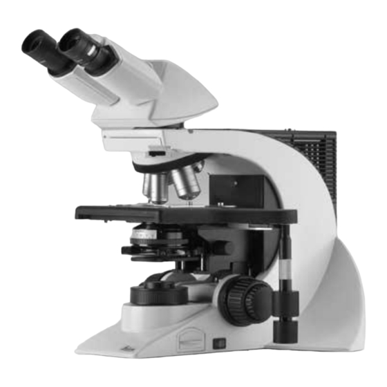
  • Seite 168 4. Geräteübersicht Abb. 1a Linke Stativseite Leica DM2000 Grob- und Feinfokussierung Kondensorhöhenverstellung Helligkeitseinstellung Leuchtfeldblende Aperturblende Kondensor Analysatoraufnahme...
  • Seite 169 4. Geräteübersicht Abb. 1b Rechte Stativseite Leica DM2000 Okulare Okularstutzen Tubus Aufnahme für Objektivprismenschieber Objektivrevolver mit Objektiven Objekttisch mit Präparatehalter Einbaubeleuchtung Ein-/Ausschalter Kondensorhöhenverstellung 10 Grob- und Feinfokussierung 11 Koaxialtrieb zur x-, y-Tischverschiebung...
  • Seite 170 4. Geräteübersicht Abb. 2 Linke Stativseite Leica DM2500 Lampenhaus 10 Kondensorscheibe Grob- und Feinfokussierung 11 Kondensor Helligkeitseinstellung 12 Objekttisch mit Präparatehalter Kondensorhöhenverstellung 13 Objektivrevolver mit Objektiven Einstellung Leuchtfeldblende 14 Objektivprismenschieber Ein-/Ausschalter 15 Tubus Leuchtfeldblende 16 Okularstutzen Koaxialtrieb zur x-, y-Tischverschiebung...
  • Seite 171 13 Seitliche Funktionstasten zum Wechsel zwischen zwei Aufnahme für Objektivprismenschieber Objektivvergrößerungen oder zum Durchschalten der Objektivrevolver mit Objektiven Vergrößerungen (größer/kleiner) Objekttisch mit Präparatehalter analog linke Stativseite Einbaubeleuchtung Ein-/Ausschalter Weitere Bedienelemente siehe Abb. 1b Leica DM2000. Kondensorhöhenverstellung 10 Grob- und Feinfokussierung 11 Koaxialtrieb zur x-, y-Tischverschiebung...
  • Seite 172: Auspacken

    5. Auspacken 5. Auspacken Aufstellungsort Entnehmen Sie zunächst vorsichtig alle Kompo- nenten dem Transport- und Verpackungsmaterial. Das Arbeiten mit dem Mikroskop sollte in einem staubfreien Raum erfolgen, der frei von Öl- und anderen chemischen Dämpfen und extremer Luftfeuchtigkeit ist. Am Arbeitsplatz sollen Hinweis: außerdem große Temperaturschwankungen, Das Berühren der Linsenoberfläche der Objekti-...
  • Seite 173 5. Auspacken Transport Für den Versand oder Transport des Mikroskops und seiner Zubehörkomponenten sollte die Originalverpackung verwendet werden. Um Beschädigungen durch Erschütterungen zu vermeiden, sollten vorsorglich folgende Kom- ponenten demontiert und gesondert verpackt werden: • Schrauben Sie die Objektive heraus. •...
  • Seite 174: Montage Des Mikroskops

    6. Montage 6. Montage des Mikroskops 6.1 Objekttisch Die Mikroskopkomponenten werden sinnvoller- weise in dieser Reihenfolge montiert: Achtung: • Zubehör Objekttisch • Kondensor Vor der Komplettierung des Objekttisches dür- • Fluoreszenz* fen noch keine Objektive eingeschraubt sein! • Zwischensysteme* • Tubus Präparatehalter •...
  • Seite 175 6. Montage • Stecken Sie zunächst den flachen Fokus- Feintriebknopf auf der Seite auf, an der Sie den Koaxialtrieb befestigen wollen. Der Knopf wird magnetisch gehalten (5.1). Achten Sie darauf, dass der Knopf einrastet. Der andere Fokusknopf wird entsprechend auf der gegen- überliegenden Seite befestigt.
  • Seite 176: Kondensor

    Kondensor an, so dass der Kondensor arre- tiert wird. • Nur für Leica DM3000: Abb. 10 Kondensorhalter Bei Verwendung des motorisierten Konden- Kondensorzentrierung sors Kondensorkabel anschließen. Klemmschraube für Kondensor Kondensorhöhenverstellung Abb. 8 Kondensorunterseite (Beispiel CL/PH) Orientierungsstift Zusatzlinse LS (für Leica DM2000/3000)
  • Seite 177: Tubus Und Okulare

    6. Montage 6.3 Tubus und Okulare 6.4 Objektive Grundsätzlich nur Leica Objektive der Tubus- länge × (unendlich) verwenden! Standard- Hinweis: gewindemaß ist M25. Es wird empfohlen, die Objektive so anzuordnen, dass die Vergrößerung Für Fluoreszenzanwendungen muss zuerst der ansteigt, wenn der Objektivrevolver im Uhrzei- Fluoreszenzilluminator montiert werden →...
  • Seite 178: Lichtquelle Für Die Durchlichtachse

    Anschlag gerade in den werden. Sockel. Achten Sie darauf, dass die Lampe gerade sitzt. Nur für Leica DM2000/3000: Lampenwechsel bei der Einbaubeleuchtung • Entfernen Sie die Schutzhülle der Lampe. Die Durchlichtbeleuchtung mit Niedervolt- Halogenglühlampe (Abb. 13) ist im Mikroskopfuß...
  • Seite 179 6. Montage Nur für Leica DM2500: • Stecken Sie die neue Lampe 12V 100W (14b.1) mit der Schutzhülle bis gegen den Anschlag Lampenwechsel beim Lampenhaus 107/2 gerade in den Sockel. Achten Sie darauf, dass Dieses Lampenhaus wird mit einer 12V 100W die Lampe gerade sitzt.
  • Seite 180: Komponenten Für Fluoreszenzanwendungen

    6. Montage 6.6 Komponenten für Fluoreszenzanwendungen Einsetzen der Gasentladungslampen (Hg und Xe) in das Lampenhaus 106z 6.6.1 Fluoreszenzilluminator Hg- und Xe-Lampen werden mit separaten Vor- Der Fluoreszenzilluminator wird vor dem Tubus schaltgeräten betrieben. montiert. Die Befestigung erfolgt über die seitli- Bitte unbedingt die gesonderte Anleitung dieser che Klemmschraube.
  • Seite 181 6. Montage Folgende Gasentladungslampen sind einsetzbar erfordern unterschiedliche Stromver- sorgungsgeräte und Lampenfassungen (Abb. 19): Typische Lebensdauer* Hg-Höchstdrucklampe 50 W (Wechselstrom) 100 h Hg-Höchstdrucklampe 100 W (Gleichstrom) 200 h Hg-Höchstdrucklampe 100 W (Gleichstrom Typ 103 W/2) 300 h Xe-Hochdrucklampe 75 W (Gleichstrom) 400 h * Bitte beachten Sie die Datenblätter der Lampenhersteller.
  • Seite 182 6. Montage • Setzen Sie die Lampenfassung wieder ein und Abb. 20 Anschluss Lampenhaus 106z Lampenhausaufnahme ziehen Sie die Befestigungsschrauben (18.8) wieder an. • Schließen Sie das Lampenhaus und ziehen Sie die Befestigungsschrauben wieder an. • Setzen Sie das Lampenhaus an die Auflicht- Lampenhausaufnahme (20.1) an und befesti- gen Sie es mit der seitlichen Klemmschraube.
  • Seite 183: Bestückung Der Fluoreszenz-Revolverscheibe

    6. Montage 6.6.3 Bestückung der Fluoreszenz-Revolverscheibe Zum Einsetzen der Filter- bzw. Reflektorwürfel gehen Sie folgendermaßen vor: • Entfernen Sie den Analysator (Abb. 23.1). • Ziehen Sie die Frontabdeckung (Abb. 23.2) nach vorne ab. Abb. 23 Fluoreszenzachse • Setzen Sie einen Filterwürfel bzw. Reflektor- Analysator würfel in die Ihnen frontal zugewandte Frontabdeckung...
  • Seite 184: Analysator Und Polarisator

    • Stecken Sie stattdessen den Polarisatorhalter (Abb. 27) auf. • Stecken Sie den Polarisator mit der beschrif- teten Seite nach oben in die untere Öffnung. Abb. 26 Montage des Polarisatorhalters Analysatoraufnahme Klemmschraube Abb. 27 Filterhalter mit 2 Positionen für Leica DM2000/3000...
  • Seite 185: Lambda-Plattenkompensator

    6. Montage 6.8 Lambda-Plattenkompensator* 6.10 Optionales Zubehör • Drehen Sie den Kondensator bis zum oberen Kamera Anschlag hoch. Über einen Adapter kann eine Kamera kann an- geschlossen werden. • Entfernen Sie gegebenenfalls das Filter- magazin DLF auf dem Stativfuß. • Setzen Sie den Adapter auf den oberen Ab- gang des Tubus auf und befestigen Sie ihn mit •...
  • Seite 186 Ergolift Für das Stativ steht ein Stativuntersatz zur Ver- fügung, der in der Höhe und Neigung über Stell- Abb. 29 Diskussionseinrichtung (hier mit Leica DM1000) räder verstellt werden kann, um eine optimale Bewegung des Leuchtzeigers in x- und y-Richtung und Umschaltung des Farbfilters Arbeitsposition zu erhalten.
  • Seite 187: Anschluss An Die Stromversorgung

    Der Anschluss eines PCs am Leica DM3000 (31b.3) ist nur notwendig, wenn neue Objektive eingelernt werden oder eine Umbelegung der seitlichen Funktionstasten durchgeführt werden soll. Dies ist nur über die Software Leica DMControl möglich. Abb. 31a Stativrückseite Leica DM2000/DM2500 Abb. 31b Stativrückseite Leica DM3000...
  • Seite 188: Inbetriebnahme

    Hinweis: Bedingt durch den Aus- und Wiedereinbau des Sofern nichts anderes angegeben ist, gelten für Kondensors kann jedoch in einigen Fällen eine das Mikroskop Leica DM3000 die gleichen Nachzentrierung des Kondensors nötig sein. Bedienungshinweise wie für das Mikroskop Überprüfen deshalb Kondensor- Leica DM2000.
  • Seite 189 Schlüssel ist magnetisch an der Unterseite halter des Tisches ein. des Tisches befestigt. • Fokussieren Sie auf das Präparat mit dem Fokushandrad (32.2). Abb. 33 Leica DM2500 Fokushandrad Helligkeitseinstellung Kondensorhöhenverstellung Abb. 34 Leica DM2000 Leuchtfeldblendeneinstellung Kondensorhöhenverstellung Ein-/Ausschalter Helligkeitseinstellung Kondensorzentrierung Leuchtfeldblende Tischpositionierung Kondensorzentrierung...
  • Seite 190: Phasenkontrastringe Überprüfen

    7. Inbetriebnahme • Öffnen Sie die Leuchtfeldblende so weit, dass 7.3 Phasenkontrastringe überprüfen sie gerade aus dem Sehfeld verschwindet Ist Ihr Mikroskop für die Verwendung von (35d). Phasenkontrast ausgerüstet, ist die Kondensor- scheibe bereits mit den zu den Objektiven pas- senden Lichtringen bestückt Die Lichtringe sind bereits werkseitig zentriert.
  • Seite 191: Justieren Der Kondensor-Prismen

    7. Inbetriebnahme • Setzen Sie anstelle eines Okulars das Einstell- • Drehen Sie die Zentrierschlüssel, bis der fernrohr (Abb. 36) in den Beobachtungstubus dunkle Ring (Phasenring im Objektiv) de- ein. ckungsgleich mit dem geringfügig schmaleren hellen Ring (Lichtring im Kondensor) ist (37c). •...
  • Seite 192 7. Inbetriebnahme • Schwenken Sie ein geeignetes Objektiv ein Bei richtiger Justierung muss der dunkle Strei- und stellen Sie das Präparat scharf. fen in der Mitte des aufgehellten kreisförmigen Feldes liegen. • Schwenken Sie gegebenenfalls den Kondensor- Ist eine Justierung notwendig, gehen Sie kopf ein.
  • Seite 193: Justieren Der Lichtquellen

    7. Inbetriebnahme 7.5 Justieren der Lichtquellen • Legen Sie ein Blatt Papier auf den Objekttisch und fokussieren Sie die Oberfläche mit einem Eine Zentrierung ist nur bei Verwendung des Trockenobjektiv schwacher bis mittlerer Ver- Lampenhauses 106z notwendig. größerung. • Bei Verwendung eines Vorschaltgerätes wird •...
  • Seite 194 7. Inbetriebnahme Zentrieren der Quecksilberlampe Hg 50 W Abb. 42 Direktes Bild des Lichtbogens fokussiert, aber dezentriert (in Wirklichkeit ist das Bild unschärfer) • Auf dem Papier sehen Sie das direkte Bild des Lichtbogens und das Spiegelbild, die in der Regel gegeneinander verschoben sind.
  • Seite 195 7. Inbetriebnahme Zentrieren der Quecksilberlampen Abb. 45 Direktes Bild des Lichtbogens fokussiert, aber dezentriert (in Wirklichkeit ist das Bild unschärfer) Hg 100 W und Xe 75 W • Auf dem Papier sehen Sie das direkte Bild des Lichtbogens und das Spiegelbild, die in der Regel gegeneinander verschoben sind.
  • Seite 196 7. Inbetriebnahme Achtung! Bei älteren Lampen ist die Struktur des Lichtbogens nicht mehr klar erkennbar. Das Bild ähnelt dann mehr dem einer HG 50-Lam- pe. Bild und Spiegelbild können daher nicht mehr exakt übereinander plaziert werden. Bringen Sie in diesem Fall beide Bilder zur Deckung.
  • Seite 197: Bedienung

    • Zum Verlängern ziehen Sie den unteren Griff (49b.1) nach unten. Dann führen Sie den obe- Schalten Sie das Mikroskop am Ein/Aus-Schal- ren Griff (49b.2) entsprechend nach. ter (48.1, bei Leica DM2500 auf der anderen Stativseite) ein. Einstellen der Gängigkeit (Drehmoment) Das Drehmoment kann individuell durch zwei Rändel (49b.2, 49b.4) für X und Y angepasst wer-...
  • Seite 198: Fokussierung

    8. Bedienung Rechts-/Linksbedienung 8.3 Fokussierung Der Koaxialtrieb lässt sich sowohl rechts wie Grob- und Feinfokussierung auch links am Tisch befestigen. (Siehe auch Auf beiden Stativseiten befinden sich Fokus- Montage S. 20). Zum Wechseln der Seite gehen handräder zur Grob- und Feinfokussierung Sie folgendermaßen vor: (Abb.
  • Seite 199 8. Bedienung • Umfassen Sie den rechten und linken Fokus- Fokusschwelle einstellen knopf gleichzeitig und und schieben Sie die Die aktuelle Position kann durch Feststellen des Knöpfe mit leichtem Druck nach oben bzw. Rändelrades (51.1) am rechten Fokusknopf als nach unten in die gewünschte Position. Fokusschwelle gesetzt werden.
  • Seite 200: Tuben

    8. Bedienung 8.4 Tuben Okularauszug an Armlänge anpassen • Am Tubus AET22 können die Okulare bis zu 30 mm ausgezogen werden (Abb. 53). Hinweis: Verschließen Sie nicht benutzte Tubusaus- Strahlenteilung bei Fototuben gänge, da sonst Streulicht die Beobachtung stören kann. Tubus EDT22: Die Lichtaufteilung zwischen Beobachtungs- und Dokumentationsausgang ist fest eingestellt...
  • Seite 201: Okulare

    8. Bedienung Tubus HC L 2TU: 8.5 Okulare Die Lichtaufteilung wird manuell durch Heraus- ziehen einer Schaltstange eingestellt. Hinweis: Schaltstange Beobachtung Foto Der Blendschutz der Okulare muss beim Mikro- 100 % skopieren mit Brille abgenommen bzw. zurück- PHOTO 110 % 100 % gestülpt werden.
  • Seite 202: Objektive

    • Verwenden Sie bei Immersionsobjektiven das entsprechende Immersionsmedium. Objektivwechsel OIL: nur optisches Immersionsöl nach DIN/ Die Objektive werden beim Leica DM2000 und ISO verwenden. DM2500 manuell in den Strahlengang einge- Reinigung → S. 70 schwenkt. Achten Sie darauf, dass der Revolver Wasserimmersion.
  • Seite 203: Die Funktionstasten Beim Leica Dm3000

    8. Bedienung 8.7 Die Funktionstasten beim Leica DM3000 Im Togglemodus wird beim Drücken einer der seitlichen Funktionstasten zwischen zwei zuvor Auf dem Frontbedienfeld befinden sich sechs eingelernten Vergrößerungen hin- und her- schwarze Tasten zur direkten Anwahl eines Ob- geschaltet. Die werkseitig vordefinierten Objek- jektivs.
  • Seite 204 8. Bedienung Standardmodus Togglemodus Die Toggle-Taste ist aus. Ausgehend vom Standardmodus wird durch Die Taste für das aktuelle Objektiv leuchtet grün. einen kurzen Druck auf die Toggle-Taste zum Mit den seitlichen Funktionstasten können Togglemodus umgeschaltet. Die Toggle-Taste nacheinander die Objektive eingeschwenkt wer- leuchtet nun grün.
  • Seite 205 Funktionstasten gelegt werden, so- leuchtet grün. Die Taste des zweiten Objektivs dass die Position des Kondensorkopfes vom Be- leuchtet weiterhin gelb. nutzer eingestellt werden kann. Umbelegung der Funktionstasten ist nur über Software Leica DMControl möglich und erfor- dert den Anschluss eines PCs.
  • Seite 206 • Schalten Sie die Lampe am Vorschaltgerät • Für jedes Objektiv ist bereits werkseitig die ein. Lichtintensität voreingestellt. Über das Stell- rad (analog zu 57.1 beim DM2000) kann dieser Wert verändert werden. Der neue Wert wird Achtung! für das jeweilige Objektiv gespeichert und au-...
  • Seite 207 8. Bedienung 8.9 Aperturblende für das Auge merkliche Verminderung des Auf- lösungsvermögens tritt bei Schließen der Die Aperturblende (59.3) im Kondensor bestimmt Aperturblende unter ca. 0.6x des Objektivs ein Auflösung, Tiefenschärfe und Kontrast des mi- und sollte möglichst vermieden werden. kroskopischen Bildes.
  • Seite 208 8. Bedienung 8.10 Leuchtfeldblende Die Leuchtfeldblende (58.2, 59.5) schützt das Präparat vor unnötiger Erwärmung und hält al- les nicht zur Abbildung benötigte Licht vom Ob- jekt fern, so dass der Kontrast gesteigert wer- den kann. Deshalb öffnet man sie immer nur so weit, dass das beobachtete oder fotographierte Objektfeld gerade ausgeleuchtet wird.
  • Seite 209: Kontrastverfahren

    Die Kondensoren UCL bzw. UCLP sind ohne Zu- satz ebenfalls ab einer Vergrößerung 4x ver- Die Kondensoren UCA/P und Achr.Apl.0.9 (P) wendbar. können ohne Zusatz ab einer Vergrößerung von Für das Leica DM2500 mit Objektiven < 10x ist die 1.25x eingesetzt werden. Anpassungslinse (Streuscheibe) notwendig. Kondensorkopf wird...
  • Seite 210: Hellfeld

    9. Kontrastverfahren Objektivvergrößerungen 1.6x und 2.5x* Abb. 60 Filteraufnahmen Mit den Kondensoren CL/PH bzw. CLP/PH, UCL Nur Leica DM2000/3000: Filtermagazin DLF zum bzw. UCLP sind Vergrößerungen 1.6x und 2.5x Aufsetzen ebenfalls möglich, wenn der Kondensor kom- Mikroskopfuß plett entfernt wird. Die Leuchtfeldblende wird dann funktionell zur Aperturblende.
  • Seite 211: Phasenkontrast

    9. Kontrastverfahren 9.1.2 Phasenkontrast 9.1.3 Dunkelfeld • Legen Sie ein Durchlichtpräparat auf. • Legen Sie ein Durchlichtpräparat auf. • Schwenken Sie ein geeignetes Objektiv ein. • Schwenken Sie ein geeignetes Objektiv ein. Objektive, die für Phasenkontrast geeignet sind, tragen die Gravur PH. •...
  • Seite 212: Schiefe Beleuchtung

    9. Kontrastverfahren Für das Leica DM2000, DM2500 und DM3000 ste- 9.1.5 Polarisation hen Spezial-Dunkelfeld-Kondensoren zur Verfü- • Schwenken Sie ggf. die Lambda-Platte des gung (Abb. 61). Lambda-Plattenkompensators aus. Die Verwendbarkeit der DF-Kondensoren hängt von der Apertur der benutzten Objektive ab. Bei •...
  • Seite 213: Differentieller Interferenzkontrast

    9. Kontrastverfahren 9.1.6 Differentieller Interferenzkontrast Achtung! • Legen Sie ein Präparat auf, schwenken Sie Polarisator unbedingt mit der beschrifteten ein geeignetes Objektiv ein und fokussieren Seite nach oben benutzen, da sonst das inte- Sie das Präparat. grierte Wärmeschutzfilter unwirksam ist und der Polarisator unbrauchbar wird (Verfär- •...
  • Seite 214 9. Kontrastverfahren Für Polarisator ICT/P*: Schwenken Sie den Polarisator an der Unter- seite des Kondensors in den Strahlengang ein. Stellen Sie sicher, dass der rote Index- punkt an der Frontseite des Polarisators auf 0 steht. • Stecken Sie den Objektiv-Prismenschieber in den Tubusschlitz (Abb.
  • Seite 215: Fluoreszenz

    9. Kontrastverfahren 9.2 Fluoreszenz • Legen Sie ein geeignetes Präparat auf und fahren Sie ein entsprechendes Objektiv an. • Fokussieren Sie das Bild eventuell zunächst im Durchlicht. • Schalten Sie die Auflichtquelle am externen Vorschaltgerät ein. • Öffnen Sie den Shutter. •...
  • Seite 216: Messungen Mit Dem Mikroskop

    10. Messungen mit dem Mikroskop 10. Messungen mit dem Mikroskop 10.1 Längenmessungen Für Längenmessungen sind erforderlich: Hinweise: - Strichplatte mit Teilung im Okular oder Tubus Verwendung eines Vergrößerungs- HC FSA 25 PE mit Diaeinspiegelung oder ein wechslers muss der Vergrößerungsfaktor be- digitales Längenmessokular.
  • Seite 217: Dickenmessungen

    10. Messungen mit dem Mikroskop 10.2 Dickenmessungen Objektmarkierer Dickenmessungen sind im Prinzip durchführbar, Er wird statt eines Objektivs eingeschraubt. wenn sowohl die Objektunterseite als auch die Durch Drehen eines absenkbaren Ritzdiamanten Objektoberseite eindeutig fokussierbar ist. Aus können zur Objektmarkierung Kreise von varia- Differenz Tischhöheneinstellung blem Radius ins Deckglas bzw.
  • Seite 218: Differenzierung Von Gicht/Pseudogicht

    10. Messungen mit dem Mikroskop 10.3 Differenzierung von Gicht/Pseudogicht Im folgenden Abschnitt wird das grundlegende Verfahren Differenzierung von Gicht/ Die Durchführung dieses Test setzt die Verwen- Pseudogicht erklärt. Dieser Test beruht auf der dung des Lambda-Plattenkompensators voraus. negativen Doppelbrechung von Uraten und der Montage →...
  • Seite 219 10. Messungen mit dem Mikroskop • Kippen Sie den Ausrichtungshebel (68.1) bis Verfahren zur Bestimmung von Pseudogicht: zum rechten Anschlag. Nun werden die paral- Der Pseudogicht-Test wird genauso durchge- lelen Kristalle blau und die senkrechten Kris- führt wie der Gicht-Test. Die Farbveränderung talle gelb dargestellt (Abb.
  • Seite 220: Trouble Shooting

    11. Trouble Shooting 11. Trouble Shooting Problem Ursache/Abhilfe Stativ Das Mikroskop reagiert nicht. Stellen Sie sicher, dass Spannung auf der Steckdose liegt. Stellen Sie sicher, dass das Stativ an das Netz angeschlossen ist. Überprüfen Sie die Kabelverbindungen. Überprüfen Sie, ob die Sicherung defekt ist und wechseln Sie sie ggf.
  • Seite 221 11. Trouble Shooting Problem Ursache/Abhilfe Fluoreszenz: Die Lampe zündet nicht sofort nach Schalten Sie das Vorschaltgerät mehrmals an dem Einschalten. und aus. Lassen Sie Hg-Lampen vor dem erneuten An- schalten erst abkühlen. Hellfeld Das Präparat ist nicht zu fokussieren. Verwenden Sie das korrekte Immersions- medium.
  • Seite 222 11. Trouble Shooting Problem Ursache/Abhilfe Phasenkontrast Es lässt sich kein Phasenkontrast einstellen. Das Präparat ist zu dick, zu dünn oder zu stark gefärbt. Brechzahl von Einschlussmittel und Objekt ist identisch, sodass kein Phasensprung ent- steht. Das Deckglas ist nicht gleichmäßig aufgelegt. Überprüfen Sie, ob der richtige Lichtring ein- gestellt ist (→...
  • Seite 223 11. Trouble Shooting Problem Ursache/Abhilfe Fluoreszenz Das Bild ist absolut dunkel (keine Fluoreszenz). Öffnen Sie den Shutter (→ S. 61). Überprüfen Sie die Antigen-Antikörper-Kombi- nation. Setzen Sie eine neue Lampe ein (→ S. 26ff). Die Fluoreszenz ist zu schwach. Zentrieren Sie die Lampe (→ S. 39ff) Setzen Sie eine neue Lampe ein (→...
  • Seite 224: Pflege Des Mikroskops

    12. Pflege des Mikroskops 12.Pflege des Mikroskops 12.2 Reinigung Achtung! Vor Reinigungs- und Wartungsarbeiten Netz- Achtung: stecker ziehen! Faser- Staubreste können Elektrische Komponenten vor Feuchtigkeit Fluoreszenzmikroskopie störende Untergrund- schützen! fluoreszenz erzeugen. Mikroskope in warmen und feucht-warmen Kli- Reinigen lackierter Teile maten brauchen besondere Pflege, um einer Staub und lose Schmutzpartikel können mit Fungusbildung vorzubeugen.
  • Seite 225: Umgang Mit Säuren Und Basen

    Vermeiden Sie unter allen Umständen die di- Schäden auf innenliegenden Flächen, so rekte Berührung von Optik und mechani- sind die Objektive zur Instandsetzung an Ihre schen Teilen mit diesen Chemikalien. Leica-Niederlassung zu schicken. Auch von einer Reinigung der Innenflächen der Okula- re wird abgeraten. 12.4 Sicherungswechsel Der Sicherungseinschub (Abb.
  • Seite 226: Verschleiß- Und Ersatzteile

    13. Wichtigste Verschleiß- und Ersatzteile 13.Wichtigste Verschleiß- und Ersatzteile Bestell-Nummer Sach-Nummer Bezeichnung Verwendung für Ersatzlampen 11 500 319 Halogenglühlampe 12 V 30 W Einbaubeleuchtung 11 500 974 Halogenglühlampe 12 V 100 W Lampenhaus 107/2 11 500 137 Hg-Höchstdrucklampe 50 W Lampenhaus 106 z 11 500 138 Hg-Höchstdrucklampe 100 W...
  • Seite 227: Nachrüstungen

    Linse* 2.5x einsetzen lassen. größte Bohrung für Hellfeld- beobachtung (= BF), die etwas kleineren für Lichtringe bzw. λ- und λ/4-Plättchen oder die Anpassungslinse 2.5x. Abb. 72 Kondensor UCL Befestigungsschraube für Kondensorscheibe Abb. 71 Durchlichtfiltermagazin für Leica DM2500...
  • Seite 228 14. Nachrüstungen Achtung: Hinweise: Vor dem Einbau der Scheibe in den Kondensor Bei Verwendung einer kleineren Bohrung für darauf achten, dass keine Zentrierschraube Hellfeld kann die maximale Beleuchtungs- seitlich übersteht. apertur nicht genutzt werden. • Befestigen Sie die Kondensorscheibe mittels Die Beschriftung ( z.B.
  • Seite 229 14. Nachrüstungen Einsetzen der DIC-Kondensor-Prismen: Achtung: Mit K usw. beschriftete Prismen in die gro- ßen Bohrungen wie folgt einsetzen: Vor dem Einbau der Scheibe in den Kondensor darauf achten, dass keine Zentrierschraube • Drehen Sie die Zentrierschrauben etwas zu- seitlich übersteht. rück.
  • Seite 230: Index

    Lampenwechsel Durchlicht 24 BG38 61 Gängigkeit 43, 45 Längenmessungen 62 Gasentladungslampen 26, 27, 28 LAS 13 DIC-Prismen 31 Geschwindigkeitsumschaltung 45 Leica Application Suite 13 Dickenmessungen 63 Gicht/Pseudogicht 64 Lernmodus 49, 51 Differentieller Interferenzkontrast 59 Grobfokussierung 44 Leuchtfeldblende 52, 53, 54 Diskussionseinrichtungen 32 Lichtintensität 52...
  • Seite 231 15. Index Polarisator 30, 58 Umgebungsbedingungen 18 Polarisator ICT/P 60 Polarisatorhalter 30 Vergrößerungswechsler 32 Präparatehalter 20 Verlängern des Koaxialtriebs 43 Vorschaltgerät 26, 43 Quecksilberlampe Hg 50 W 40 Quecksilberlampe Xe 75-Brenner 27 Hg 100 W/Xe 75 W 41 Zeicheneinrichtung 33 Rechts-/Linksbedienung 44 Zentrierung Lichtringe 37 Reinigung 70...
  • Seite 232: Eu-Konformitätserklärung

    16. EU-Konformitätserklärung 16. EU-Konformitätserklärung Download: DM2000: http://www.light-microscopy.com/down_ce-declaration_dm2000 DM2500: http://www.light-microscopy.com/down_ce-declaration_dm2500 DM3000: http://www.light-microscopy.com/down_ce-declaration_dm3000...
  • Seite 233 Leica DM2000 Leica DM2500 Leica DM3000 Mode d’emploi...
  • Seite 234 – même partielle – par impression, photocopie, microfilm ou autres procédures, dont celles impliquant des systèmes électroni- ques, n’est permise qu’avec l’autorisation ex- presse et écrite de Leica Microsystems Wetzlar GmbH. Les informations contenues dans le présent document représentent l’état actuel de la tech- nique et de la science.
  • Seite 235 8.5 Oculaires ............. 47 8.6 Objectifs ............48 Fonction des microscopes ...... 8.7 Le panneau de commandes du Leica DM3000 ........49 Consignes de sécurité ......8.8 Sources de lumière ........52 3.1 Consignes générales de sécurité ..8.9 Diaphragme d’ouverture ......53 3.2 Sécurité...
  • Seite 236: Remarques Importantes Concernant Ce Mode D'emploi

    1. Remarques importantes concernant ce mode d’emploi 1. Remarques importantes concernant ce mode d’emploi Attention ! Ce mode d’emploi contient des instructions et Ce mode d’emploi est un élément essentiel informations importantes pour la sécurité de du microscope. Il convient de le lire attenti- fonctionnement et le maintien en bon état de vement avant l’assemblage, la mise en ser- marche du microscope et des accessoires.
  • Seite 237: Fonction Des Microscopes

    2. Fonction des microscopes 2. Fonction des microscopes Les microscopes Leica DM2000, DM2500 et DM3000 dont ce mode d’emploi est un élément, Attention ! sont prévus pour les applications de routine et la recherche en biologie. Ces applications Le fabricant décline toute responsabilité...
  • Seite 238: Consignes De Sécurité

    Toute interruption du conducteur de protec- naison avec des composants d’un autre fa- tion à l’intérieur ou à l’extérieur de l’instru- bricant que Leica et sortant du cadre de ce ment, ou toute suppression de la connexion mode d’emploi, il est impératif de se rensei- au conducteur de protection peut rendre dan- gner auprès du représentant Leica local ou...
  • Seite 239 à celle du microscope. Pour une mise en réseau sans conducteur de protec- tion, demander conseil au SAV de Leica. Attention ! Avant de remplacer les fusibles ou les lam- Attention ! pes, il est impératif de mettre le commuta-...
  • Seite 240: Vue D'ensemble

    4. Vue d’ensemble 4. Vue d’ensemble Leica DM2000 Leica DM2500 Spécification • diascopie : fond clair, fond noir, contraste de phase, polarisation Méthode de contraste Contraste interférentiel • épiscopie : fluorescence Éclairage halogène intégré Module d’éclairage Entièrement automatisé Réglage manuel de : Réglage manuel de :...
  • Seite 241 4. Vue d’ensemble Spécification Leica DM2000 Leica DM2500 Condenseur • condenseur CL/PH 0.90/1.25 OIL avec repères en couleur (pour le DM2500 avec des objectifs < 10x, il faut utiliser le coulisseau pour lumière parasite) • condenseur CLP/PH 0.85 pour polarisation (pour le DM2500 avec des objectifs <...
  • Seite 242 4. Vue d’ensemble Leica DM3000 Spécification • diascopie : fond clair, fond noir, contraste de phase, polarisation Méthode de contraste Contraste interférentiel • épiscopie : fluorescence Éclairage halogène intégré Entièrement automatisé Réglage manuel de : • diaphragme d’ouverture • diaphragme de champ •...
  • Seite 243 • commutation de la vitesse (en option) • réglage du seuil de mise au point et de la direction du pas Interfaces USB2 Leica Application Suite (LAS) pour Windows 2000, XP pour Logiciel l’apprentissage des objectifs et la configuration des touches de...
  • Seite 244 4. Vue d’ensemble Fig. 1a Côté gauche du statif Leica DM2000 Mise au point grossière et fine Changement de hauteur du condenseur Réglage de la luminosité Diaphragme de champ lumineux Diaphragme d’ouverture Condenseur Logement de l’analyseur...
  • Seite 245 4. Vue d’ensemble Fig. 1b Côté droit du statif Leica DM2000 Oculaires Tube oculaire Tube Logement du coulisseau de prismes d’objectif Revolver à objectifs équipé Platine porte-objet avec guide-objet Éclairage intégré Interrupteur Changement de hauteur du condenseur 10 Mise au point grossière et fine...
  • Seite 246 4. Vue d’ensemble Fig. 2 Côté gauche du statif Leica DM2500 Module d’éclairage 10 Tourelle de condenseur Mise au point grossière et fine 11 Condenseur Réglage de la luminosité 12 Platine porte-objet avec guide-objet Changement de hauteur du condenseur 13 Revolver à objectifs équipé...
  • Seite 247 Platine porte-objet avec guide-objet grand/plus petit Éclairage intégré Côté gauche analogue du statif Interrupteur Changement de hauteur du condenseur Autres éléments de commande cf. fig. 1b Leica DM2000. 10 Mise au point grossière et fine...
  • Seite 248: Déballage

    5. Déballage 5. Déballage 5. Déballage Lieu d'installation Commencer par sortir avec précaution tous les composants du carton de transport et d’embal- L’utilisation du microscope doit se faire dans lage. une pièce exempte de poussière, d’huile et de vapeurs chimiques, et bénéficiant d’un taux d’hygrométrie modéré.
  • Seite 249 5. Déballage Transport Il convient d’utiliser l’emballage d’origine pour expédier ou transporter le microscope et ses accessoires. Pour éviter des dommages dus aux secousses, démonter les composants suivants et les embal- ler à part : • dévisser les objectifs ; •...
  • Seite 250: Assemblage Du Microscope

    6. Assemblage du microscope 6. Assemblage du microscope 6.1 Platine L’assemblage des composants du microscope doit s’effectuer logiquement dans l’ordre suivant : Attention : • platine porte-objet accessoire • condenseur Ne visser aucun objectif avant d’avoir fini de • fluorescence* monter la platine porte-objet ! •...
  • Seite 251 6. Assemblage du microscope • Installer d’abord le bouton plat de la mise au point fine du même côté que le levier de com- mande x-y de la platine . Le bouton est main- tenu en place par un aimant (5.1). Veiller à la bonne mise en place du bouton.
  • Seite 252: Condenseur

    Brancher le câble du condenseur lors de l’uti- Fig. 10 Support du condenseur lisation du condenseur motorisé. Centrage du condenseur Vis de serrage du condenseur Bouton de réglage en hauteur du condenseur Fig. 8 Bas du condenseur (exemple CL/PH) Broche d’orientation Lentille additionnelle LS (pour Leica DM2000/3000)
  • Seite 253: Tube Et Oculaires

    Il est recommandé de visser les objectifs après Fig. 11 Fixation du tube avoir effectué le raccordement à l’alimentation Vis de serrage → p. 33. Fig. 12 Panneau de commandes frontal du Leica DM3000 Choix de l’ objectif Toggle Plaques avec grossissement de l’objectif...
  • Seite 254: Source De Lumière Pour L'axe De Diascopie

    être placées dans des boîtiers fermés. • Placer la nouvelle lampe avec son enveloppe protectrice dans le culot jusqu’à la butée. Seulement pour le Leica DM2000/3000: Veiller à ce que la lampe soit bien en place. Changement de lampe de l'éclairage incorporé...
  • Seite 255 6. Assemblage du microscope Seulement pour le Leica DM2500: • Placer la nouvelle lampe 12 V 100 W (14b.1) et son enveloppe protectrice dans le culot jus- Changement de lampe avec le boîtier de lampe qu’à la butée. Veiller à ce que la lampe soit 107/2 bien en place.
  • Seite 256: Composants Des Applications En Fluorescence

    6. Assemblage du microscope 6.6 Composants des applications en fluorescence Installation des lampes à décharge (Hg et Xe) dans le boîtier de lampe 106z 6.6.1 Illuminateur à fluorescence Les lampes Hg et Xe fonctionnent avec des ré- L’illuminateur à fluorescence se monte avant le gulateurs de puissance séparés.
  • Seite 257 6. Assemblage du microscope Il est possible d'installer les lampes à décharge suivantes (ce qui impose des alimentations et des douilles de lampes différents) (fig. 19) : Type durée de vie moyenne* Lampe Hg 50 W, ultra-haute pression (courant alternatif) 100 h Lampe Hg 100 W, ultra-haute pression (courant continu) 200 h...
  • Seite 258 6. Assemblage du microscope • Remettre en place la douille de lampe et ser- Fig. 20 Connexion du boîtier de lampe 106z Logement du boîtier de lampe rer à nouveau les vis de fixation (18.8). • Fermer le boîtier de lampe et serrer à nouveau les vis de fixation.
  • Seite 259 6. Assemblage du microscope 6.6.3 Équipement de la roue de fluorescence Pour installer le bloc de filtre ou de réflecteur, procéder comme suit : • Tirer le couvercle frontal (fig. 23) vers l’avant. • Installer un bloc de filtre ou de réflecteur dans le support qui est de face .
  • Seite 260: Analyseur Et Polariseur

    • Monter le porte-polariseur (fig. 27). • Placer le polariseur à la position la plus basse du porte filtre, inscription vers le haut. Fig. 26 Montage du porte-polariseur Logement de l’analyseur Vis de serrage Fig. 27 Porte-filtre à 2 positions pour Leica DM2000/3000...
  • Seite 261: Compensateur À Lame Lambda

    6. Assemblage du microscope 6.8 Compensateur à lame Lambda* 6.10 Accessoires en option • Tourner le condenseur et l’orienter vers le Caméra haut jusqu’à la butée supérieure. Un adaptateur permet de connecter une caméra. • Enlever le cas échéant le magasin à filtres •...
  • Seite 262 (29.2). La fixation s’effectue avec la vis latérale. Dispositif de rehausse ergonomique Fig. 29 Dispositif de discussion (ici avec Leica DM1000) Déplacement du pointeur lumineux en direction x et y Une base est disponible pour le statif ; des mo- et commutation du filtre chromatique lettes permettent d’en régler la hauteur et l’incli-...
  • Seite 263: Connexion Au Bloc D'alimentation

    Fig. 30 Traceur Remarque : Capuchon Il n’est utile de raccorder un PC au Leica DM3000 (31b.3) que lorsque de nouveaux objec- tifs doivent être programmés ou lorsque un changement au niveau des commandes latéra- les de fonction doit être effectué. Cela n’est possible qu’à...
  • Seite 264: Mise En Service

    Dans certains cas, un centrage complémentaire Si rien n’est indiqué, la notice d’utilisation du du condenseur est nécessaire (après montages Leica DM3000 est la même que celle du Leica et démontages successifs du condenseur) . DM2000. C’est pourquoi il convient de vérifier le centrage du condenseur.
  • Seite 265 <10x.) • Le réglage en hauteur du condenseur (33.3, 34.1) permet de régler le condenseur jusqu’à Pour le Leica DM3000 : ce que le bord du diaphragme de champ soit Pour basculer l’objectif, appuyez sur la net.
  • Seite 266: Vérification Des Anneaux De Contraste De Phase

    7. Mise en service • Ouvrir le diaphragme de champ jusqu’à ce 7.3 Vérification des anneaux de contraste de qu’il disparaisse du champ de vision (35d). phase Si le microscope est équipé en contraste de phase, la tourelle de condenseur est déjà équipée des anneaux de lumière adaptés aux objectifs.
  • Seite 267: Condenseur

    7. Mise en service • Installer à la place d’un oculaire la lunette de • Tourner les clefs de centrage jusqu’à ce que mise au point (fig. 36) dans le tube d’observa- l’anneau sombre (anneau de phase dans l’ob- jectif) soit superposé à l’anneau clair légère- tion.
  • Seite 268 7. Mise en service • Placer dans le trajet optique l’ objectif appro- Si l’ajustement est correct, la ligne sombre doit prié et faire une mise au point sur la prépara- être au milieu du champ circulaire éclairé. tion. Si un ajustement est nécessaire, procéder comme suit : •...
  • Seite 269: Ajustement Des Sources De Lumière

    7. Mise en service 7.5 Ajustement des sources de lumière • Poser une feuille de papier sur la platine porte-objet et faire une mise au point de la Un centrage est nécessaire uniquement en cas surface avec un objectif à sec de gran- d’utilisation du boîtier de lampe 106z.
  • Seite 270 7. Mise en service Centrage de la lampe au mercure Hg 50 W Fig. 42 Image directe de l’arc électrique focalisée mais décentrée (en réalité, l’image est moins nette) • Sur le papier, on voit l’image directe de l’arc électrique et l’image miroir qui sont générale- ment décalées.
  • Seite 271 7. Mise en service Centrage des lampes au mercure Fig. 45 Image directe de l’arc électrique focalisée mais décentrée (en réalité, l’image est moins nette) Hg 100 W et Xe 75 W • Sur le papier, on voit l’image directe de l’arc électrique et l’image miroir qui sont générale- ment décalées.
  • Seite 272 7. Mise en service Attention ! Avec des lampes usagées , la structure de l’arc électrique est diffuse. L’image ressem- ble plus à celle d’une lampe HG 50. Dans ce cas, il n’est plus possible de superposer exactement image directe et image miroir. Dans ce cas, faire coïncider les deux ima- ges.
  • Seite 273: Utilisation

    (49b.1). Asservir ensuite la poignée du haut (49b.2). Mettre sous tension le microscope avec l’inter- rupteur (48.1, pour le Leica DM2500, de l’autre côté du statif). Réglage de la direction du pas (couple de rotation) Le couple de rotation peut être réglé...
  • Seite 274: Mise Au Point

    8. Utilisation Utilisation à droite/gauche 8.3 Mise au point Le levier de commande coaxiale peut se fixer à Mise au point grossière et fine droite ou à gauche de la platine. (Voir aussi la Des deux côtés du statif se trouvent les rubrigue : Assemblage p.
  • Seite 275 8. Utilisation • Saisir simultanément les boutons droit et gau- Réglage du seuil de mise au point che de la mise au point et amener les boutons Le réglage de la position actuelle s’effectue en à la position souhaitée en appuyant légère- bloquant la roue moletée (51.1) sur le bouton ment vers le haut ou le bas.
  • Seite 276 8. Utilisation 8.4 Tubes Adapter la longueur du tube porte-oculaire à la longueur de bras • Sur le tube AET22, il est possible d’allonger le Remarque : tube porte-oculaire de 30 mm (fig. 53). Obturer soigneusement les sorties libres du tube, pour éliminer toute lumière parasite .
  • Seite 277: Mise Au Point

    8. Utilisation Tube HC L 2TU : 8.5 Oculaires Le réglage de la répartition lumineuse s’effectue manuellement avec une tirette de commande. Remarque : Tirette de commande Observation Photo Les oeillères anti-éblouissement des oculaires 100 % doivent être enlevées et retournées pour les PHOTO 110 % 100 %...
  • Seite 278: Objectifs

    Changement d'objectif OIL : n’utiliser que l’huile à immersion Pour le Leica DM2000 et le DM2500, les objectifs optique selon DIN/ISO. Nettoyage → p. 70 doivent être basculés manuellement. Pour le Leica DM3000, la commande se fait par immersion d’eau.
  • Seite 279: Le Panneau De Commandes Du Leica Dm3000

    8. Utilisation 8.7 Le panneau de commandes du En mode Toggle, vous pouvez passer d’un gros- Leica DM3000 sissement à un autre, en appuyant sur une des commandes latérales de fonction. Les objectifs Sur le panneau de commandes frontal se trou- pré-définis par le constructeur peuvent être lé-...
  • Seite 280 8. Utilisation Mode Standard Mode Toggle La touche Toggle n’est pas en marche. En partant du mode Standard, vous pouvez pas- La touche de l’objectif actuel est éclairée en sez en mode Toggle en appuyant rapidement sur vert. Les objectifs peuvent être basculés les uns la touche Toggle.
  • Seite 281 éclairée en vert. La touche du deuxième objectif seur puisse être réglée par l’utilisateur. brille toujours en jaune. Le changement de fonction des touches n’est possible qu’à l’aide du logiciel Leica DMControl et demande que l’appareil soit relié à un PC.
  • Seite 282: Sources De Lumière

    Cette valeur peut Attention ! être changée à l’aide de la manette (cf. 57.1 du DM2000). La nouvelle valeur est enregis- La distance minimale entre le boîtier de trée pour l’objectif correspondant et sera lampe et le mur, les rideaux, les tapis, les li- automatiquement ajustée lorsque l’objectif...
  • Seite 283: Diaphragme D'ouverture

    8. Utilisation 8.9 Diaphragme d’ouverture l’œil nu lorsqu’on ferme le diaphragme d’ouver- ture à moins de 0.6x de la valeur d’ouverture de Le diaphragme d’ouverture (59.3) sur le conden- l’objectif ; ceci est donc déconseillé. seur détermine la résolution, la profondeur de En polarisation, le fait de fermer le diaphragme champ et le contraste de l’image microscopi- d’ouverture intensifie les couleurs.
  • Seite 284: Diaphragme De Champ

    8. Utilisation 8.10 Diaphragme de champ Le diaphragme de champ (58.2, 59.5) protège la préparation d’un échauffement éventuel et aussi des lumières parasites en vidéo, ce qui augmente le contraste de la préparation . L’on se borne donc à l’ouvrir suffisamment pour que le champ objet observé...
  • Seite 285: Méthode De Contraste

    Grossissements d'objectifs 1.25x* et 1.6x Remarque : pour le Leica DM2500 Pour le Leica DM2500 avec des objectifs < 10x, il faut utiliser le coulisseau pour lumière parasite. Les condenseurs UCA/P et Achr.Apl.0.9 (P) peu- vent s’utiliser à partir d’un grandissement de 1.25x.
  • Seite 286: Fond Clair

    Fig. 60 Logements de filtres Avec les condenseurs CL/PH ou CLP/PH, UCL ou Seulement pour le Leica DM2000/3000 : UCLP, des grandissements 1.6x et 2.5x sont égale- magasin à filtres DLF à ment utilisables quand le condenseur est complè- placer sur le pied du tement enlevé.
  • Seite 287: Contraste De Phase

    9. Méthode de contraste 9.1.2 Contraste de phase 9.1.3 Fond noir • Poser une préparation pour diascopie. • Poser une préparation pour diascopie. • Placer dans le trajet optique l’ objectif appro- • Placer dans le trajet optique l’ objectif appro- prié.
  • Seite 288: Éclairage Oblique

    9. Méthode de contraste Pour le Leica DM2000, DM2500 et DM3000, des 9.1.5 Polarisation condenseurs spéciaux pour le fond noir sont • Enlever du trajet optique la lame Lambda du disponibles (fig. 61). compensateur. L’ouverture des objectifs utilisés détermine la possibilité...
  • Seite 289: Contraste Interférentiel

    9. Méthode de contraste 9.1.6 Contraste interférentiel Attention ! • Poser une préparation, placer dans le trajet Placer impérativement le polariseur de telle optique l’objectif approprié et faire la mise au sorte que l’inscription soit vers le haut , sinon point de la préparation.
  • Seite 290 9. Méthode de contraste Pour le polariseur ICT/P* : Placer dans le trajet optique le polariseur si- tué en dessous du condenseur. Vérifier que le point indexé rouge sur le devant du polariseur est positionné sur 0. • Insérer le prisme en coulisseau d’objectif dans son logement (fig.
  • Seite 291: Fluorescence

    9. Méthode de contraste 9.2 Fluorescence • Poser une préparation appropriée et placer dans le trajet optique l’objectif correspon- dant. • Faire une mise au point de l’image, éventuel- lement en diascopie. • Mettre sous tension la source d’épiscopie sur le régulateur de puissance externe.
  • Seite 292: Mesures Avec Le Microscope

    10. Mesures avec le microscope 10. Mesures avec le microscope 10.1 Mesures de longueur Pour les mesures de longueur, il est nécessaire Remarques : d’avoir : En cas d’utilisation d’un changeur de grossisse- - réticule avec graduation dans l’oculaire ou ment, il faut tenir compte du facteur de grossis- tube HC FSA 25 PE avec réflexion de diapositi- sement ! Il est impératif de réaliser un calibrage...
  • Seite 293: Mesures D'épaisseur

    10. Mesures avec le microscope 10.2 Mesures d'épaisseur Marqueur d'objet Les mesures d’épaisseur sont en principe réali- Il est vissé à la place d’un objectif. En tournant sables à condition de pouvoir focaliser le des- le diamant, qui est réglable en hauteur, on peut sous et le dessus de l’objet.
  • Seite 294: Différenciation De La Goutte Et De La Pseudo-Goutte

    10. Mesures avec le microscope 10.3 Différenciation de la goutte et de la La chapitre suivant explique la procédure simple pseudo-goutte permettant de différencier la goutte et la pseudo-goutte. Ce test s’appuie sur la biréfrin- La réalisation de ce test présuppose l’utilisation gence négative des urates et la biréfringence du compensateur à...
  • Seite 295 10. Mesures avec le microscope • Basculer le levier d’orientation (68.1) jusqu’en Procédure d’identification de la pseudo-goutte : butée vers la droite. Les cristaux N/S parais- Le test de la pseudo-goutte s’effectue de ma- sent alors bleus et les cristaux E/O, jaunes nière identique à...
  • Seite 296: Dépannage

    11. Dépannage 11. Dépannage Problème Cause/Solution Statif Le microscope ne s’allume pas. Vérifier que la prise secteur fonctionne. Vérifier que le statif est connecté au secteur. Vérifier les connexions des câbles. Vérifier que le fusible n’est pas défectueux et le remplacer si besoin est (→ p. 71). Éclairage L’image est complètement sombre.
  • Seite 297 11. Dépannage Problème Cause/Solution Fluorescence : la lampe ne s’allume pas immé- Allumer et éteindre plusieurs fois le régu- diatement après la mise sous tension. lateur de puissance. Laisser refroidir les lampes au mercure avant la remise en marche. Fond clair La mise au point de la préparation n’est pas Utiliser le milieu d’immersion correct.
  • Seite 298 11. Dépannage Problème Cause/Solution Contraste de phase Il n’est pas possible de régler le contraste de La préparation est trop épaisse, trop mince ou phase. trop colorée. L’indice de réfraction du milieu d’inclusion et de l’objet sont identiques, de sorte qu’il n’y a aucune inversion de phase.
  • Seite 299 11. Dépannage Problème Cause/Solution Fluorescence L’image est complètement sombre (pas de Ouvrir l’obturateur (→ p. 61). fluorescence). Vérifier la combinaison antigène-anticorps. Installer une nouvelle lampe (→ p. 26 et suiv.). La fluorescence est trop faible. Centrer la lampe (→ p. 39 et suiv.) Installer une nouvelle lampe (→...
  • Seite 300: Entretien Du Microscope

    12. Entretien du microscope 12.Entretien du microscope 12.2 Nettoyage Attention ! Débrancher le microscope avant les travaux Attention : de nettoyage et de maintenance ! Les restes de fibres et de poussières peuvent al- Protéger les composants électriques de l’hu- térer l’observation en formant un arrière-plan midité...
  • Seite 301: Maniement Des Acides Et Bases

    à Il faut à tout prix éviter le contact direct de votre point de vente Leica où ils seront répa- ces produits chimiques avec l’optique ou les rés. Nous déconseillons également de pro- composants mécaniques.
  • Seite 302: Principales Pièces D'usure Et De Rechange

    13. Principales pièces d’usure et de rechange 13. Principales pièces d’usure et de rechange N° de commande N° d’article Désignation Utilisation Lampes de rechange 11 500 319 Lampe halogène 12 V 30 W Éclairage intégré 11 500 974 Lampe halogène 12 V 100 W Boîtier de lampe 107/2 11 500 137...
  • Seite 303: Adaptations Ultérieures

    λ et λ/4 ou la lentille de mise au point 2.5x. Fig. 72 Condenseur UCL Vis de fixation de la tourelle de condenseur Fig. 71 Magasin à filtres de diascopie pour Leica DM2500...
  • Seite 304 14. Adaptations ultérieures Attention : Remarques : Avant de monter la tourelle dans le condenseur, En cas d’utilisation d’un orifice plus petit pour le veiller à ce qu’aucune vis de centrage ne dé- fond-clair, il n’est pas possible d’obtenir l’ouver- passe sur le côté.
  • Seite 305 14. Adaptations ultérieures Mise en place des prismes de condenseur CIT : Attention : Monter comme suit les prismes marqués K etc. dans les grands orifices : Avant de monter la tourelle dans le condenseur, veiller à ce qu’aucune vis de centrage ne dé- •...
  • Seite 306: Index

    Lampes de rechange 72 lumière 39 Couple de rotation 43 l'éclairage de Koehler 34 Allongement du pignon coaxial 43 Leica Application Suite 13 Analyseur 30, 58 Déplacement d'objet 43 Lentille additionnelle LS 22 Angle d'observation 46 Diaphragme de champ 52, 53, 54 Lentille d'accomodation 55 Anneau de lumière 57...
  • Seite 307 15. Index Polariseur 30, 58 Polariseur ICT/P 60 Porte-condenseur 22 Porte-filtre 30, 53, 56 Porte-polariseur 30 Prise PC 33 Prismes de condenseur 31, 37 Prismes CIT 31 Programme de tube 47 Réglage en hauteur des boutons de mise au point 44 Régulateurs de puissance 26, 43 Remplacement de fusibles 71 Réticule 47...
  • Seite 308: Déclaration De Conformité Ue

    16. Déclaration de conformité UE 16. Déclaration de conformité UE Download : DM2000 : http://www.light-microscopy.com/down_ce-declaration_dm2000 DM2500 : http://www.light-microscopy.com/down_ce-declaration_dm2500 DM3000 : http://www.light-microscopy.com/down_ce-declaration_dm3000...
  • Seite 310 M I C R O S Y S T E M S...
  • Seite 311 版 权 归 属 : 2005 年 德 国 35578 Wetzlar , Er nst-Leitz-Str aße, Leica 微 系 统 Wetzlar 有 限 公 司 GmbH。 电 话 : (0 41) 29-0 · 传 真 : (0 41) 29-25 99。 LE 和...

Diese Anleitung auch für:

Dm2500Dm3000

Inhaltsverzeichnis