Werbung
Quicklinks
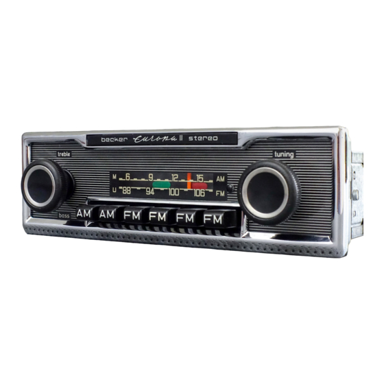
Technische Daten:
Sendereinstellung:
für alle Bereiche
a) Stationsdrucktasten 1 x LW, 1 x MW, 1 x KW,
2x UKW
b) Handabstimmung
mittels Drucktasten
Bereichsumschaltung:
Abstimmung:
Variometer
Klangblende:
kontinuierlich mit Mittelraste
Anschlußmöglichkeiten:
2 oder 4 Lautsprecher
Kurzwellen-Adapter „Reims"
Automatikantenne
Tonbandgerät (für Aufnahme und Wiedergabe)
oder Autoplattenspieler
und Verkehrsfunkadapter
Anschlußanweisung
1. Anschlußbuchse für Verkehrsfunkadapter
2. Antennenbuchse
3. Anschlußbuchse für Plattenspieler oder Tonbandgerät (Stereo)
4. Lautsprecherbuchsen
5. Buchse für KW-Adapter „Reims 10" und Automatikantenne
6. Stromversorgungskabel
Connection hints:
1. Connection socket for traffic radio adapter
2. Antenna socket
3. Connection socket for record player or tape recorder (Stereo)
4. Loudspeaker sockets
5. Socket for SW-Adapter "Reims 10" and automatic antenna
6. Cable for current supply
Änderungen vorbehalten / Modifications reserved
Technical Data:
Setting of transmitters:
for all ranges
a) Station push buttons 1 x LW, 1 x AM,
1 x SW, 2 x FM
b) manual tuning
Changing over of wave
ranges:
by push buttons
by Variometer
Tuning: Tone control:
continuous by intermediate lever
Possible connections:
2 or 4 loudspeakers
Short-wave adapter "Reims"
Automatic antenna
Tape recorder (for recording and reproduction)
or Car record player
and Traffic radio adapter
Werbung

Verwandte Anleitungen für Becker Europa II Stereo LMKU


Inhaltszusammenfassung für Becker Europa II Stereo LMKU
- Seite 1 Technische Daten: Technical Data: Sendereinstellung: für alle Bereiche Setting of transmitters: for all ranges a) Stationsdrucktasten 1 x LW, 1 x MW, 1 x KW, a) Station push buttons 1 x LW, 1 x AM, 2x UKW 1 x SW, 2 x FM b) Handabstimmung b) manual tuning Changing over of wave...
-
Seite 2: Mechanische Einstellungen
1. Mechanische Einstellungen 1. Mechanical Adjustment 1.1 Deckel abnehmen: 1.1 Removal of covers Die Deckel sind nicht verschraubt und lassen sich mit einem Schrau- The covers are not fastened by screws and can be opened by a bendreher öffnen. Dabei ist die Schraubendreherklinge zunächst in screw driver. - Seite 3 1.4 Einstellen der Kupplung 1.4 Adjustment of clutch Zwischen dem Ausrückbügel und dem Kupplungskamm muß ein Spiel Between the disengaging strap and the clutch comb a clearance of von 0,2 mm vorhanden sein. Ist dies nicht der Fall, so ist mit einem 0.2 mm is required.
- Seite 4 Blockschaltbild / Block circuit diagram 3. Abgleichanweisung 3. Alignment Hints 3.1 Abglelchvorbereitungen 3.1 Alignment Preparatlon Batteriespannung 14V, minus an Masse. NF-Teil mit P 501 und P 551 Apply battery voltage of 14 V minus to mass. Set AF-unit with P 501 and auf symmetrische Begrenzung des Ausgangssignals einstellen (Sicht- P 551 on Symmetrie limitation of Output Signal (lest with oscilloscope).
- Seite 5 ZF-Platte (340 E 0130) Leiterbahnseite UK-Platte (210 E 0120) Leiterbahnseite Rotdruck = Bestückungsseite FM IF board (340 E 0130) Printed side board (210 E 0120) Printed side Red print = Component side HF-ZF-Platte (340 E 0120) Leiterbahnseite RF-IF board (340 E 0120) Printed side...
- Seite 6 Poti-Platte (341 E 0140) Leiterbahnseite Decoder-Platte (340 E 0135) Leiterbahnseite Poti board (341 E 0140) Printed side Decoder board (340 E 0135) Printed side in rertkal posilion Widerstand steht senkrecht «-crm-o— Anschluß ist unten Entstör-Platte (341 E 0160) Leiterbahnseite NF-Platte (341 E 0150) Leiterbahnseite 7 l Suppression board (341 E 0160) Printed side 6 | AF board (341 E 0150) Printed side...
- Seite 8 3.7 Abgleichtabelle Alignment List...
- Seite 9 MKU 340...