3111018 EBC24 DE+SE+UK 20200406 Deutschland (DE) Symbole: Die folgenden Symbole werden in diesem Handbuch verwendet, um Aufmerksamkeit auf potentielle Gefahren oder auf wichtige Informationen des Produkts zu haben. Verbotszeichen: Bei Nichtbeachtung der mit einem Verbotszeichen gekennzeichneten Anweisung, ist mit schweren Verletzungen oder dem Tod zu rechnen.
EBC24 kann durch das Ändern des Setups auch: • Regulieren der Frischluftzufuhr zum Kesselraum (siehe Abschnitt 4). Handbuchstruktur: EBC24 kann entweder zur Steuerung von Schornsteinventilatoren oder zur Steuerung von Zuluftventilatoren eingesetzt werden. Der Leitfaden ist in sechs Abschnitte unterteilt: •...
PDSBOX Misst den Druck im Schornstein Rep. Schalter REP-AFB Trennschalter für Wartungsarbeiten Einbau Kabellänge Max. Kabellänge zwischen EBC24 und XTP: 100 m. Max. Kabellänge zwischen EBC24 und Schornsteinventilator / Ventilator: 100 m. Max. Kabellänge zwischen XTP und Messsonde 2 m.
• Wenn die Messsonde nach außen platziert wird, muss sie in eine • Weise installiert werden, die die Bildung von Kondenswasser oder • Eis verhindert. EBC24EU02 kommt mit einer geraden Messsonde. • EBC24 muss immer dort installiert werden, wo es vor Wind und Wetter geschützt ist (Regen, Schnee usw.) Zuluftventilator •...
3111018 EBC24 DE+SE+UK 20200406 10 • Product information 10 • Product information Achten Sie darauf, den Druckumformer (XTP) korrekt zu positionieren. Hinweis Blasen Sie nicht in die Anschlüsse des XTP !! Bei Außeninstallation ist der Drucktransmitter so anzubringen, dass er nicht dem Wetter ausgesetzt ist.
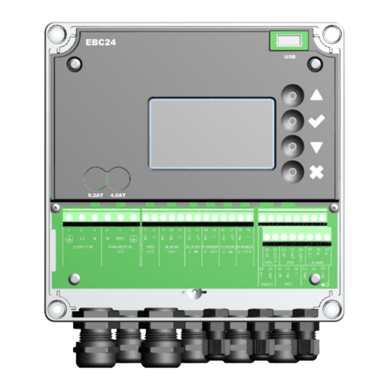
3111018 EBC24 DE+SE+UK 20200406 Product information • 11 Product information • 11 2.3.2 Klemmenbrett Im Folgenden werden die Anschlussmöglichkeiten für das Klemmenbrett erläutert Bezeichnung Kl . Verwendung Versorgung - PE Brenner 2 Relaisschalter - Normalerweise geöffnet (max. 230 VAC, 2 Verstärker)
3111018 EBC24 DE+SE+UK 20200406 12 • Product information 12 • Product information Mechanische Installation Die Steuerung und der Druckaufnehmer müssen innen installiert werden, vorzugsweise im Kesselraum. Die Steuerung muss nicht in einem Schrank installiert werden. EBC24 Control XTP-Sensor Messsonde 100 m Installieren Sie den Druckaufnehmer nicht in einem luftdichten Gehäuse.
3111018 EBC24 DE+SE+UK 20200406 Product information • 13 Product information • 13 Display Das folgende Diagramm zeigt das Layout der Anzeige auf dem EBC24. Alle möglichen Anzeigewerte sind angegeben: ZULUFT : 36 Pa : 15 % SOLLWERT : 55 Pa Der Zweck der Anzeige ist anzugeben •...
3111018 EBC24 DE+SE+UK 20200406 14 • Product information 14 • Product information 2.5.2 Einstellung der Sprache Es ist möglich die Sprache des Displays zu ändern. Die voreingestellte Sprache ist Englisch. Um die Sprache zu ändern gehen Sie wie folgt vor:...
3111018 EBC24 DE+SE+UK 20200406 Product information • 15 Product information • 15 2.5.3 Gesperrter Hauptbildschrim Der Zugriff auf das Servicemenü ist ständig möglich. Der Hauptbildschirm kann dazu gesperrt werden. Um den Code ein- oder auszuschalten gehen Sie wie folgt vor:...
3111018 EBC24 DE+SE+UK 20200406 16 • Product information 16 • Product information Einführung in die Benutzeroberfläche Menüstruktur Das Servicemenü darf nur von qualifiziertem Personal benutzt werden. Das Servicemenü besteht aus vier Hauptmenüs, die jeweils in Untermenüs unterteilt sind. HAUPTMENÜ 1 REGULERING •...
Folgen Sie bitte dem unten beschriebenen Verfahren, um den Druck im Schornstein einzustellen, : Schritt Aktion Display • Starten Sie das System SCHORNSTEINZUG : 149 Pa • EBC24 zeigt den tatsächlichen Unterdruck an (in die- : 48 % sem Beispiel 55 Pa) SOLLWERT : 55 Pa HAUPTMENU •...
Gehen Sie wie folgt vor, um die Vor- / Nachlaufzeit einzurichten: Schritt Aktion Display • Starten Sie das System SCHORNSTEINZUG : 149 Pa • EBC24 zeigt den tatsächlichen Unterdruck an (in diesem : 48 % Beispiel 55 Pa) SOLLWERT : 55 Pa HAUPTMENU •...
Um den Schornsteinzug im Schnellverfahren zu ändern folgen Sie der Anleitung unten: Schritt Aktion Display • Starten Sie die Steuerung SCHORNSTEINZUG : 149 Pa • EBC24 zeigt den tatsächlichen Unterdruck an (Bsp.: 55 Pa) : 48 % SOLLWERT : 55 Pa REGULIERUNG • Drücke SOLLWERT EINGEBEN •...
A6 Draft Input Fehlendes Signal von PDS-Funktion. Zeigt eine fehlerhafte Funktion an. A7 RS485 error Keine Kommunikation zwischen EBC24 und Modus Netzwerk A8 Priority Der Entwurf war unzureichend, und daher Kontrolle in die Priorität Zustand übergeben Überblick über das Service-Menü...
Seite 21
3111018 EBC24 DE+SE+UK 20200406 Product information • 21 Product information • 21 Menü Untermenü Funktion Display Beschreibung Klassifizierung Standard Temperaturfühler TEMP. FÜHLER Temperaturfühler Ein TEMP. FÜHLER EIN Aktiviert den Temperatursensor, die aktuelle Ein/Aus Temperatur wird angezeigt Autostart Ein AUTOSTART EIN Aktiviert das Starten des Rauchsaugers über...
3111018 EBC24 DE+SE+UK 20200406 22 • Product information 22 • Product information 3.2.1 Leuchtdioden und Klemmenbrett In der folgenden Tabelle sind die Klemmenreihen und die Leuchtdiodenanzeigen aufgelistet. Bezeichnung Max. Belastung Bedeutung, wenn die Diode geschalten ist: 1, 2 und 3...
Pressure control • 23 3111018 EBC24 DE+SE+UK 20200406 3.2.2 Umschalten zwischen den Grundfunktionen der Druckregelung und der Zuluft Standardeinstellungen EBC24 setzt auf eine ständige Druckregelung von Schornsteinventilatoren (Grundfunktion 1 Auslass / Einlass) Änderung der Grundfunktion Schritt Aktion Display SCHORNSTEINZUG : 149 Pa •...
• Wenn der EBC24 einen ausreichenden Schornsteinzug registriert, wird der Brenner freigegeben. • Der EBC24 hält den eingestellten Druck durch Regelung der Spannung. Der Druck wird im Display ange- zeigt. • Bei unzureichender Entlüftung wird der Brenner nach 15 Sekunden abgeschaltet. Eine unzureichende Entlüftung beträgt weniger als 64% des eingestellten Wertes, was weniger als 80% des Durchflusses...
1 - OUT 2 - IN 2 - OUT RS485 Dieses Beispiel zeigt, wie ein Spannungssignal (18-230 V AC / DC) an EBC24 angeschlossen wird, um den Rauchsauger zu starten/zu stoppen: • Verbinden Sie die Versorgung mit den Klemmen 1-3.
3111018 EBC24 DE+SE+UK 20200406 26 • Pressure control 4.4.2 K ontinuierlicher Betrieb FAN MOTOR SUPPLY IN VFD Out ALARM OUT BOILER BURNER BOILER BURNER 24 VDC Pt1000 1 - IN 1 - OUT 2 - IN 2 - OUT RS485 Dieses Beispiel zeigt, wie ein Spannungssignal (24 V DC) an EBC10v2 angeschlossen wird, um den Rauchsauger zu starten / zu stoppen.
1 - OUT 2 - IN 2 - OUT RS485 Dieses Beispiel zeigt, wie man einen potentialfreien Kontakt mit dem EBC24 verbindet, um den Lüfter zu starten / zu stoppen: • Verbinden Sie die Versorgungsspannung mit den Klemmen 1-3. •...
1 - OUT 2 - IN 2 - OUT RS485 Dieses Beispiel zeigt, wie man eine PDS mit EBC24 verbindet. Die PDS liefert zusätzliche Überwachung. • PDS anschließen: • Entfernen Sie die werkseitig installierte Verdrahtung zwischen den Klemmen 30 und 32.
3111018 EBC24 DE+SE+UK 20200406 Pressure-controlled regulation • 29 4.4.5 Ein Kessel mit einem potentialfreiem Kontakt und Temperaturfühlereingang FAN MOTOR SUPPLY IN VFD Out ALARM OUT BOILER BURNER BOILER BURNER 24 VDC Pt1000 1 - IN 1 - OUT 2 - IN...
1 - IN 1 - OUT 2 - IN 2 - OUT RS485 Dieses Beispiel zeigt, wie Sie den Regler EBC24 anschließen, wenn Sie den Dauerbetrieb des Schornsteinventilators benötigen: • Verbinden Sie die Versorgung mit den Klemmen 1-3. • Schleifenklemmen 13 & 17 & 28.
2 - IN 2 - OUT RS485 Dieses Beispiel zeigt, welche Eingänge / Ausgänge am EBC24 an den Frequenzumrichter angeschlossen werden müssen, wenn man zur Steuerung des Schornsteingebläses verwendet wird: Verbinden Sie die Versorgung mit den Klemmen 1-3. Frequenzumformer: ...
Die EBC24 überwacht den Druck im Kesselraum und trennt den Brenner im Fehlerfall (die Alarmdiode am EBC24 wird eingeschaltet). • Wenn sich der Druck im Kesselraum ändert, ändert die EBC24 die Lüfterdrehzahl, um den Sollwert für den Kesselraum zu erfüllen. •...
1 - IN 1 - OUT 2 - IN 2 - OUT RS485 Dieses Beispiel zeigt, welche Ein- / Ausgänge am EBC24 an den Frequenzumrichter / MPR-Relais angeschlossen werden müssen • Verbinden Sie die Versorgung mit den Klemmen 1-3. •...
Seite 34
3111018 EBC24 DE+SE+UK 20200406 Sverige (SE) Symboler: Följande symboler används genomgående i denna handbok för att uppmärksamma förekomst av potentiella faror eller viktig information om produkten. Förbudssymbol: Underlåtenhet att följa anvisningar markerade med förbudssymbol är förenat med livsfara. Farosymbol: Underlåtenhet att följa anvisningar markerade med farosymbol är förenat med risk för person- eller sakskada.
EBC24 kan genom modifierad uppsättning även: • Styra tillförseln av frisk luft till pannrummet (se avsnitt 4). Anvisningarnas uppbyggnad EBC24 kan antingen användas för att styra exodraft rökgasfläkt eller för att styra tilluftsfläktar. Anvisningarna har delats in i sex avsnitt: • Läs avsnitt 2. ”Produktinformation”.
Om fler än 2 pannor är anslutna Extern PDS PDSBOX Mäter lufttrycket i skorstenen Arbetsbrytare REP-AFB Arbetsbrytare Montering Kabellängd Max. kabellängd mellan EBC24 och XTP: 100 m Max. kabellängd mellan EBC24 och rökgasfläkt/fläkt: 100 m Max. kabellängd mellan XTP och mätgivare 2 m...
• När mätgivaren placeras utomhus måste den monteras på ett sätt som förhindrar att Obs! kondens eller is bildas. EBC24EU02 levereras med en rak mätgivare. • EBC24 ska alltid monteras så att den är skyddad från väder och vind (regn, snö osv.). Tilluftsfläkt • Montera styrningen och tryckgivaren (XTP) i pannrummet.
3111018 EBC24 DE+SE+UK 20200406 Product information • 39 Product information • 39 Se till att tryckgivaren (XTP) placeras med rätt sida upp. Obs! Blås inte i ventilerna på XTP. Vid montering utomhus ska tryckgivaren placeras så att den inte påverkas av väder och vind. Vid montering utomhus bör tryckgivaren placeras i en låda med ett hål (Ø...
3111018 EBC24 DE+SE+UK 20200406 Product information • 41 Product information • 41 Mekanisk installation Styrningen och givaren ska installeras inne, helst i pannrummet. Styrningen behöver inte installeras i ett skåp eftersom komponenterna är sammankopplade EBC24 Control 100 m Givaren kan inte monteras inuti ett lufttätt inneslutet utrymme. Pannrummets tryck/det atmosfäriska trycket används som referenstryck...
3111018 EBC24 DE+SE+UK 20200406 42 • Product information 42 • Product information Display Bilden nedan visar displayens utseende på EBC24. Alla möjliga visningsvärden anges: INTAKE : 36 Pa : 15 % SETPOINT : 55 Pa Displayen är avsedd att visa: •...
3111018 EBC24 DE+SE+UK 20200406 Product information • 43 Product information • 43 2.5.2 Ställa in språk Det är möjligt att byta språkinställningar. Standard är i Engelska. För att ändra språk på displayen, följ stegen nedan: Steg Hantering Display HUVUDMENYN • Gå till huvudmenyn 1 REGLERING •...
3111018 EBC24 DE+SE+UK 20200406 44 • Product information 44 • Product information 2.5.3 Låst startskärm Tillgång till servicemenyn är öppen som standard. Det är möjligt att låsa hemskärmen med en kod. För att stänga av/på koden, för stegen nedan: Steg...
3111018 EBC24 DE+SE+UK 20200406 Product information • 45 Product information • 45 Introduktion till användargränssnittet Menystruktur Servicemenyn ska bara användas av utbildad personal Servicemenyn är indelad i 4 huvudmenyer som alla har undermenyer. HUVUDMENYN 1 REGLERING • 1. Reglering 2 LARM •...
Följ metoden nedan för att ställa in trycket i skorstenen: Steg Hantering Display • Starta systemet SKORSTENSDRAG : 149 Pa • EBC24 visar det aktuella trycket (i detta exempel 55 Pa) : 48 % BÖRVÄRDET : 55 Pa HUVUDMENYN • Håll in i 5 sekunder för att öppna servicemenyn...
Använd följande metod för att ställa in Pre/post-purge:: Steg Hantering Display • Starta systemet SKORSTENSDRAG : 149 Pa • EBC24 visar det aktuella trycket (i detta exempel 55 Pa) : 48 % BÖRVÄRDET : 55 Pa HUVUDMENYN • Håll in i 5 sekunder för att öppna huvudmenyn...
För att snabbt komma åt menyn för tryck, följ stegen nedan: Steg Hantering Display • Starta systemet SKORSTENSDRAG : 149 Pa • EBC24 visar det aktuella negativa trycket (i detta exempel, : 48 % 55 Pa BÖRVÄRDET : 55 Pa REGLERING •...
3111018 EBC24 DE+SE+UK 20200406 Product information • 49 Product information • 49 Inställningar och felsökning Felkoder De flesta terminalanslutningar övervakas för korrekt drift. Lysdioder indikerar driftstatus. Om en lysdiod tänds indikerar det att allt fungerar som det ska, medan en släckt lysdiod visar på ett problem i den krets som den övervakar. Dessutom visas felkoder på...
Seite 50
3111018 EBC24 DE+SE+UK 20200406 50 • Product information 50 • Product information Meny Undermeny Funktion Display Beskrivning Klassificering Standard Temperature sensor TEMP. SENSOR Aktivera Sensor AKTIVERA TEMP Aktiverar temperatursensorn och displayerna AV/PÅ den aktuella temperaturen på huvudskärmen Aktivera autostart AKTIV. AUTOSTART Aktiverar temperaturen som startsignal för...
3111018 EBC24 DE+SE+UK 20200406 Product information • 51 Product information • 51 3.2.1 Lysdioder och kopplingsplint I nedanstående schema förklaras anslutningsalternativen för kopplingsplintar och lysdiodernas olika färger. Betegnelse Max. belastning Lysdiode angiver ved: 1, 2 og 3 SUPPLY IN 230-240 V AC +/- 10 % grön: EBC20 är ansluten till nätström...
3111018 EBC24 DE+SE+UK 20200406 52 • Pressure control 3.2.2 Växla mellan grundfunktionerna tryckstyrning och tilluft Fabriksinställning EBC24 är fabriksinställd för konstanttrycksreglering av exodraft rökgasfläktar (grundfunktion 1 Exhaust / Intake) Byte av grundfunktion Steg Hantering Display SKORSTENDRAG : 149 Pa •...
Anslutning av tryckgivare (XTP) och frekvensomformare måste utföras med en skärmad kabel Arbetsbrytare exodraft a/s betonar att det i enlighet med EU:s maskindirektiv måste finnas en arbetsbrytare i den fasta installationen . Arbetsbrytaren levereras inte av exodraft, men kan köpas som tillbehör .
SUPPLY IN 1 - IN 1 - OUT 2 - IN 2 - OUT RS485 Detta exempel visar hur du ansluter en spänningssignal (10–230 V AC/DC) för EBC24 för att starta/stoppa rökgasfläkten. • Anslut strömförsörjningen till plintarna 1–3. • Ansluta pannan: •...
Pressure control • 55 3111018 EBC24 DE+SE+UK 20200406 4.4.2 Kontinuerlig drift FAN MOTOR VFD Out ALARM OUT BOILER BURNER BOILER BURNER 24 VDC Pt1000 SUPPLY IN 1 - IN 1 - OUT 2 - IN 2 - OUT RS485 Detta exempel visar hur du ansluter en spänningssignal (24 V DC) för EBC10v2 för att starta rökgasfläkten.
1 - IN 1 - OUT 2 - IN 2 - OUT RS485 Detta exempel visar hur du ansluter en PDS till EBC24. PDS är en extra övervakning. • Ansluta PDS: • Ta bort den fabriksmonterade kopplingen mellan plint 30 och 32.
1 - IN 1 - OUT 2 - IN 2 - OUT RS485 Eksemplet viser hvorledes en potentialfri kontakt forbindes til EBC24 for at starte/stoppe røgsugeren: • Forsyningen tilsluttes klemme 1-3. • Tilslutning til kedel: Den potentialfri kontakt fra kedlen tilsluttes klemme 12 & 29.
2 - IN 2 - OUT RS485 Detta exempel visar hur man kopplar en potentiell fri kontakt till EBC24 för att starta/stoppa fläkten: • Anslut matningsspänningen till anslutningarna 1-3. • Anslutning till pannan: • Anslut den potentiella fria kontakten till terminalerna 12 och 29.
1 - OUT 2 - IN 2 - OUT RS485 Detta exempel visar vilka ingångar/utgångar på EBC24 som ska anslutas till frekvensomformaren när rökgasfläkten ska regleras via en frekvensomformare: Anslut strömförsörjningen till plintarna 1–3. Frekvensomformare: Anslut plint 7 och 8 till start-/stoppingången på frekvensomformaren.
1 - OUT 2 - IN 2 - OUT RS485 Detta exempel visar hur du ansluter EBC24 om du vill ha kontinuerlig drift av rökgasfläkten: • Anslut strömförsörjningen till plintarna 1–3. • Koppla ihop plint 13 och 17 och 28.
• EBC24 kan reglera en tilluftsfläkt direkt eller indirekt via en frekvensomformare Placering Montera EBC24 och tryckgivaren (XTP) i pannrummet såsom beskrivs i avsnittet 2.2 Montering, sidan 6 och 7 Driftsmetod Allmänt • EBC24 övervakar trycket i pannrummet och stänger av brännaren i händelse av fel (larmdioden på EBC24 tänds).
1 - IN 1 - OUT 2 - IN 2 - OUT RS485 Detta exempel visar vilka ingångar/utgångar på EBC24 som måste vara anslutna till frekvensomformaren/MPR-reläet. • Anslut strömförsörjningen till plintarna 1–3. • Koppla ihop plint 13 och 28. •...
Seite 63
3111018 EBC24 DE+SE+UK 20200406 English (UK) Symbols: The following symbols are used throughout this manual to bring attention to potential danger or to important information about the product. Prohibition symbol: Failure to observe instructions marked with a prohibition symbol is associated with serious injury or death.
Product information • 65 Product information • 65 Product information Description EBC24 (exodraft Boiler Control) is a specially developed control component for constant pressure regulation of chimney draft. Available in two variants: • EBC24EU01 is suitable for indoor installation •...
Measures pressure in the chimney Rep. switch REP-AFB Isolation switch Fitting Cable length Max. cable length between EBC24 and XTP: 100 m. Max. cable length between EBC24 and chimney fan / fan: 100 m. Max. cable length between XTP and measuring probe 2 m.
• When the measuring probe is placed outside, it must be installed in a manner that pre- vents the formation of condensation or ice. EBC24EU02 comes with a straight measuring probe. • EBC24 must always be installed where it is protected from wind and weather (rain, snow, etc.) Supply air fan •...
3111018 EBC24 DE+SE+UK 20200406 68 • Product information 68 • Product information Make sure to position the pressure transducer (XTP) correctly. Note Do not blow into the valves of the XTP. For outdoor installation, place the pressure transducer where it is not exposed to the weather. For outdoor installation, the pressure transducer should be placed in a box fitted with a hole (Ø2mm) in the bottom.
3111018 EBC24 DE+SE+UK 20200406 Product information • 69 Product information • 69 2.3.2 Terminal board The following explains connection options for the terminal board Terminal Betegnelse Terminal PE Ground Burner 2 relay switch-Nor- mally open (max. 230 VAC, 2 amps.)
3111018 EBC24 DE+SE+UK 20200406 70 • Product information 70 • Product information Mechanical installation The control and the transducer must be installed inside, preferably in the boiler room. The control does not need to be installed in a cabinet. EBC24 Control 100 m Do not install the transducer in an airtight enclosure.
3111018 EBC24 DE+SE+UK 20200406 Product information • 71 Product information • 71 Display The diagram below shows the layout of the display on the EBC24. All possible display values are indicated: INTAKE : 36 Pa : 15 % SETPOINT : 55 Pa The purpose of the display is to indicate: •...
3111018 EBC24 DE+SE+UK 20200406 72 • Product information 72 • Product information 2.5.2 Setting the language It is possible to change the language on the display. The default setting is in English. To set the language on the screen, follow these steps:...
3111018 EBC24 DE+SE+UK 20200406 Product information • 73 Product information • 73 2.5.3 Locked home screen Access to the service menu is open as a default. It is possible to lock the home screen with a code. To turn the code on/off, follow these steps:...
3111018 EBC24 DE+SE+UK 20200406 74 • Product information 74 • Product information Introduction to the user interface Menu Only qualified personnel should use the service menu The service menu consists of four main menus, each divided into submenus. HOVEDMENY •...
To set the pressure in the chimney, follow the procedure detailed below: Step Action Display • Start the system EXHAUST : 149 Pa • EBC24 displays the actual negative pressure (in this : 48 % example, 55 Pa) SETPOINT : 55 Pa MAIN MENU • Press and hold...
To set up pre-/post-purge period, follow procedure below: Step Action Display • Start the system INTAKE : 149 Pa • EBC24 displays the actual negative pressure (in this exam- : 100 % ple, 55 Pa) SETPOINT : 55 Pa MAIN MENU • Press and hold...
To access the set point menu quickly, follow the procedure below: Step Action Display • Start the system INTAKE : 149 Pa • EBC24 displays the actual negative pressure (in this exam- : 100 % ple, 55 Pa) SETPOINT : 55 Pa REGULATION • Press SET PRESSURE •...
A6 Draft Input Missing signal from PDS function. Indicates a defective function. A7 RS485 error No communication between EBC24 and modbus network A8 Priority The draft has been insufficient and therefore the control has been in priority Overview of the service menu The service menu is built in 4 levels and associated submenus.
Seite 79
3111018 EBC24 DE+SE+UK 20200406 Product information • 79 Product information • 79 Menu Sub-menu Function Display Description Classification Standard Temperature Sensor TEMP. SENSOR Enable Sensor ENABLE SENSOR Enables the temperature sensor and displays On/Off the current temperature on the main screen...
3111018 EBC24 DE+SE+UK 20200406 80 • Pressure control 3.2.1 Light-emitting diodes and terminal board The chart below lists the terminal board connection options and light-emitting diode displays. Designation Max. load Meaning when the light-emitting diode is: 1, 2 og 3...
Pressure control • 81 3111018 EBC24 DE+SE+UK 20200406 3.2.2 Switch between the basic functions of pressure control and supply air Default settings EBC24 defaults to constant pressure regulation of exodraft chimney fans (basic function 1 Exhaust/Intake) Change of basic function Step Action Display •...
. Wiring examples As a constant pressure regulator for exodraft chimney fans, the EBC24 can be connected to a range of different signals. The following pages are wiring examples and illustrate the following: 4 .4 .1 One boiler 4 .4 .2 Continuous operation...
1 - OUT 2 - IN 2 - OUT RS485 This example shows how to connect a voltage signal (18-230 V AC/DC) to EBC24 to start/stop the chimney fan. • Connect the supply to terminals 1-3. • Connecting the boiler: •...
1 - OUT 2 - IN 2 - OUT RS485 The example shows how a voltage signal (24 V DC) is connected to EBC24 for the chimney fan to run continuously. • Connect the supply to terminals 1-3. • Loop terminals 12 and 29.
1 - IN 1 - OUT 2 - IN 2 - OUT RS485 This example shows how to connect a PDS to EBC24. The PDS supplies extra monitoring • Connecting PDS: • Remove the factory installed wiring between terminals 30 and 32.
1 - OUT 2 - IN 2 - OUT RS485 This example shows how to connect a potential free contact to the EBC24 to start/stop the fan: • Connect the supply voltage to terminals 1-3. • Connection to the boiler: •...
1 - OUT 2 - IN 2 - OUT RS485 This example shows which inputs/outputs on the EBC24 need to be connected to the frequency converter, when one is used to control the chimney fan: • Connect the supply to terminals 1-3.
1 - OUT 2 - IN 2 - OUT RS485 This example shows how to connect the EBC24 if you require continuous operation of the chimney fan: • Connect the supply to terminals 1-3. • Loop terminals 13 & 17 & 28.
EBC an control a supply air fan directly or indirectly via a frequency converter. Positioning 24 cInstall the EBC24 and the pressure transducer (XTP) in the boiler room as described in section 2.2 Fitting, pages 6+7 Mode of operation General function •...
1 - IN 1 - OUT 2 - IN 2 - OUT RS485 This example shows which inputs/outputs on the EBC24 need to be connected to the frequency converter/MPR-relay: • Connect the supply to terminals 1-3. • Loop terminals 13 & 28.
92 • EU declaration of conformity 3111018 EBC24 DE+SE+UK 20200406 EU Declaration Of Conformity Declaration of Conformity DK: EU-Overensstemmelseserklæring NL: EU-Conformiteits verklaring GB: Declaration of Conformity SE: EU-Överensstämmelsedeklaration DE: EU-Konformitätserklärung EU-Vaatimustenmukaisuusvakuutus FR: Déclaration de conformité de l’Union Européenne ESS-Samræmisstaðfesting NO: EU-Samsvarserklæring Dichiarazione di Conformità...