Inhaltsverzeichnis
Werbung
Verfügbare Sprachen
Verfügbare Sprachen
Quicklinks
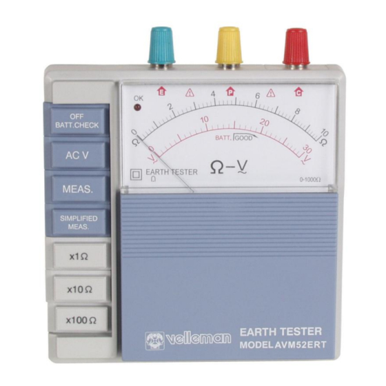
AVM52ERT – Analogue Earth Resistance Tester
1. Introduction & Features
Thank you for buying the AVM52ERT ! Please read the manual carefully before bringing this
device into service.
•
The modern design limits the influence of the earth voltage and the earth resistance of
auxiliary earth bars to a minimum.
•
Press the BATT.CHECK button to test the auxiliary earth resistance and the connection
cable. The OK lamp lights up when the device is ready to perform accurate earth resistance
measurements.
•
Low power consumption : max. 12V/100mA.
•
Push buttons allow smooth operation of the device.
•
The earth resistance value can be read directly from the scale.
•
You only need to press the SIMPLIFIED MEAS. button for simplified measurements. No
shorting wire is required since terminals P and C can be shorted internally simply by
pressing this button.
•
Battery replacement is easy.
•
The carrying case in hard plastic is water-resistant and accommodates all accessories.
2. Specifications
Measuring Ranges
Earth Resistance
Earth Voltage
Accuracy
Earth Resistance
Earth Voltage
Measurement System
Measure earth resistance with a CC inverter, 800Hz, ± 2mA
Measure earth voltage through a rectifier, type 5KΩ/V, ± 40~500Hz
Withstand Voltage
Self-Check Facility
Batteries
Dimensions
Weight
Accessories
• test leads (red15m / yellow 10m / green 5m)
• auxiliary earth bars
• carrying case
AVM52ERT
10/100/1000Ω
30V AC (5KΩ/V approx.)
±5% of full scale
±5% of full scale
1500V AC for 60 seconds between electrical circuit and the housing.
Press the BATT.CHECK button to test the earth resistance and the
connection with terminals P and C. The OK lamp comes on.
8 x 1.5V AA-battery
140 (L) x 140 (W) x 90 (D) mm
±800g
1
VELLEMAN
Werbung
Inhaltsverzeichnis

Verwandte Anleitungen für Velleman AVM52ERT


Inhaltszusammenfassung für Velleman AVM52ERT
- Seite 1 AVM52ERT – Analogue Earth Resistance Tester 1. Introduction & Features Thank you for buying the AVM52ERT ! Please read the manual carefully before bringing this device into service. • The modern design limits the influence of the earth voltage and the earth resistance of auxiliary earth bars to a minimum.
- Seite 2 Where it is not possible to drive the auxiliary earth bars into the ground (e.g. concrete) you should just put the earth bars down, cover them with a cloth and pour (preferably salt) water over them. This may allow earth resistance measurements. Note that this does not work with an asphalt surface. AVM52ERT VELLEMAN...
- Seite 3 OK lamp to stay off and for the needle to exceed the upper limit value. This can be due to several things : the tested device may not be functioning properly, its cables may be damaged or the green connection cable may be damaged. AVM52ERT VELLEMAN...
- Seite 4 Let us also assume that RE is 100Ω and that the earth resistance to be measured is e.g. 100Ω. Consequently, the true earth resistance is expressed as : REX = (100Ω) – re Since re is greater than 0, a true earth resistance may be expressed as follows : REX ≤ 100Ω AVM52ERT VELLEMAN...
-
Seite 5: Battery Replacement
This instrument must be used by a competent, trained person and operated in strict accordance with the instructions. Velleman does not accept liability for damage or injuries caused by misuse or non-compliance with the instructions or safety procedures. It is essential that you read, understand and respect the safety rules contained in this manual. -
Seite 6: Metingen Uitvoeren
Open het batterijvak en stel de nulregelschroef bij met een schroevendraaier indien de naald niet op de 0 staat. U kunt het deksel van het batterijvak onder een hoek van max. 90° plaatsen met de rest van de behuizing. AVM52ERT VELLEMAN... - Seite 7 Opmerking : De meting van aardspanning wordt niet beïnvloed indien de x1Ω, x10Ω of de x100Ω knop is ingedrukt. 3) Batterijspanning & kabelaansluiting controleren U kunt tezelfder tijd volgende zaken controleren wanneer de BATT.CHECK knop zich in de ingedrukte stand bevindt : AVM52ERT VELLEMAN...
- Seite 8 2V. Druk op de “x10Ω” knop en dan op de MEAS. knop. Lees de spreidingsweerstand af. Druk de “x100Ω” knop in indien de naald volledig naar rechts overhelt. AVM52ERT VELLEMAN...
-
Seite 9: Batterijen Vervangen
Indien we een spreidingsweerstand meten van een paar tientallen ohms, dan mogen we ervan uitgaan dat de uitgelezen spreidingsweerstand een werkelijke waarde is. 5. Batterijen vervangen 1. Klap het batterijdeksel 90° open. 2. Hef het lipje op dat zich centraal aan de bovenkant van het batterijvak bevindt. AVM52ERT VELLEMAN... -
Seite 10: Spécifications
Dit toestel moet worden bediend door een geschoold persoon en in overeenstemming met de instructies in deze handleiding. Velleman is niet aansprakelijk voor schade of kwetsuren die werden veroorzaakt door ongeoorloofd gebruik of het niet naleven van de veiligheidsrichtlijnen. Het is van groot belang dat u de veiligheidsrichtlijnen leest en ook begrijpt. U moet deze richtlijnen strikt volgen wanneer u het toestel gebruikt. - Seite 11 Vérifiez si la position de départ de l’aiguille correspond avec la position du 0 sur l’échelle Ω ou V. Ouvrez le compartiment des piles et ajustez le zéro mécanique si l’aiguille n’est pas sur le "0". Le couvercle du compartiment des piles se laisse ouvrir 90°. AVM52ERT VELLEMAN...
- Seite 12 00Ω se trouve dans la position enfoncée. 3) Contrôler la tension des piles & la connexion des câbles Quand le bouton BATT.CHECK ("contrôle des piles") est enfoncé, il est possible de contrôler les données suivantes : AVM52ERT VELLEMAN...
- Seite 13 “x100Ω” si l’aiguille bascule à l’extrême droite. Le résultat indiqué (RE) est une valeur représentant la résistance de terre approximative. Il ne faut créer de court-circuit externe comme les bornes de connexion P et C sont court-circuitées de façon interne. AVM52ERT VELLEMAN...
-
Seite 14: Remplacement Des Piles
3. Tirez le support des piles du compartiment. 4. Enlevez les piles et insérez 8 nouvelles piles du type LR6 (AA). Respectez les indications de polarité. 5. Insérez le support dans le boîtier et refermez le compartiment des piles. AVM52ERT VELLEMAN... -
Seite 15: Especificaciones
Seules les personnes qualifiées peuvent opérer cet appareil. Respectez les instructions de la notice. Velleman ne sera pas responsable de dommages ou de blessures causées par le non respect des instructions de la notice ou par une utilisation défendue. Il est très important de lire, de comprendre et de respecter les instructions de la notice. -
Seite 16: Realizar Mediciones
“0”. Se puede abrir la tapa del compartimiento de pilas 90°. b) Conectar los cables Clave las picas auxiliares P y C en la tierra tal como se muestra en la siguiente figura. Fig. 2 AVM52ERT VELLEMAN... - Seite 17 Cortocircuite las pinzas cocodrilos al extremo del cable amarillo y rojo para verificar si no han sido dañados. Note que no necesita cables a fin de controlar el estado de carga de pilas. Sólo apriete el botón BATT.CHECK una vez. La lámpara no se iluminará. AVM52ERT VELLEMAN...
- Seite 18 El método simplificado sólo usa dos bornes de conexión. Añada la resistencia de tierra “re” de un electrodo de tierra conectado al borne de conexión P a la verdadera resistencia de tierra REX. Para la resistencia de tierra se usa la siguiente fórmula : RE = REX + re Fig. 3 AVM52ERT VELLEMAN...
-
Seite 19: Avm52Ert - Analoges Prüfgerät Für Erdungswiderstand
Se pueden modificar las especificaciones y el contenido de este manual sin previo aviso. AVM52ERT – Analoges Prüfgerät für Erdungswiderstand 1. Einführung und Eigenschaften Wir bedanken uns für den Kauf des AVM52ERT! Lesen Sie diese Bedienungsanleitung vor Inbetriebnahme sorgfältig durch. • Dank des modernen Entwurfs bleibt der Einfluss der Erdungsspannung und der Erdungswiderstand von zusätzlichen Erdspießen beschränkt. -
Seite 20: Technische Daten
140 (L) x 140 (B) x 90 (D) mm Gewicht ±800g Zubehör • Messleitungen (rot15m / gelb/ 10m, grün 5m) • zusätzliche Erdspieße • Tragekoffer Abb. 1 3. Beschreibung 1. OK-Lampe 4. Anschlussklemmen 2. Funktionsknöpfe 5. Skale 3. Knöpfe für Ω-Bereich 6. Batteriefachdeckel AVM52ERT VELLEMAN... -
Seite 21: Messungen Durchführen
Wenn der Widerstand der zusätzlichen Erdspieße höher ist als 2KΩ, könnte dies zu Messfehlern führen. Seien Sie also vorsichtig wenn Sie zusätzliche Erdspieße P1 und C1 in der feuchten Erde stecken. Überprüfen Sie auch ob die Kabel richtig an die Anschlussklemmen angeschlossen sind. AVM52ERT VELLEMAN... - Seite 22 überprüfen” (siehe vorige Seite). Es könnte passieren, dass die OK-Lampe nicht brennt und dass die Nadel den Maximumwert der Skale trotz aller vorhergehenden Überprüfungen überschreitet. Es sind verschiedene Ursachen möglich : fehlerhaftes Funktionieren des geprüften Gerätes, beschädigte Anschlusskabel des Gerätes oder Beschädigung des grünen Anschlusskabel. AVM52ERT VELLEMAN...
- Seite 23 Lassen wir annehmen, dass “re” ein bekannter Wert ist : Lassen wir auch annehmen, dass RE = 100Ω und, dass der Ausbreitungswiderstand, der Sie messen möchten, z.B. 100Ω ist. Der wirkliche Ausbreitungswiderstand kann dann wie folgt ausgedrückt werden : AVM52ERT VELLEMAN...
- Seite 24 Übereinstimmung mit der Anweisungen in dieser Anleitung erfolgen. Bei Schäden, die durch Nichtbeachtung der Bedienungsanleitung verursacht werden, erlischt der Garantieanspruch. Für daraus resultierende Folgeschäden übernimmt Velleman keine Haftung. Es ist von äußerster Wichtigkeit, dass Sie die Sicherheitshinweise lesen und auch begreifen.