WIKA DI32-1 Betriebsanleitung

Verwandte Anleitungen für WIKA DI32-1


Inhaltszusammenfassung für WIKA DI32-1
- Seite 1 Operating instructions Betriebsanleitung Digital indicator, model DI32-1 Digitalanzeige, Typ DI32-1 Digital indicator, model DI32-1...
- Seite 69 7.9 Menübaum ..........93 WIKA Betriebsanleitung Digitalanzeige, Typ DI32-1...
- Seite 70 12.6 Menübaum ..........118 WIKA Betriebsanleitung Digitalanzeige, Typ DI32-1...
- Seite 71 19. Technische Daten ......... . 132 Konformitätserklärungen finden Sie online unter www.wika.de...
-
Seite 72: Allgemeines
Es gelten die allgemeinen Geschäftsbedingungen in den Verkaufsunterlagen. ■ Technische Änderungen vorbehalten. ■ Weitere Informationen: ■ - Internet-Adresse: www.wika.de / www.wika.com - Zugehöriges Datenblatt: AC 80.13 - Anwendungsberater: Tel.: +49 9372 132-0 Fax: +49 9372 132-406 info@wika.de WIKA Betriebsanleitung Digitalanzeige, Typ DI32-1... -
Seite 73: Aufbau Und Funktion
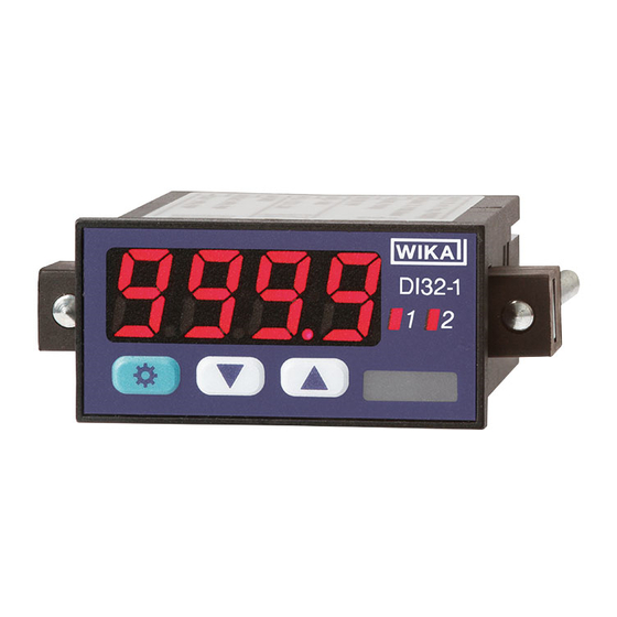
Ruft MAX-Speicher auf Verändert untere Grenzwerte Wechselst zwichen Paremetern Ändert Paremeterwerte Schaltpunktanzeige Zeigt Status der Schaltausgänge Befestigungselement mit Dient der Befestigung Spannschrauben 7-Segmentanzeige Zeigt Messwerte, Programmnummern oder Parameter an Typenschild Enthält Produktinformationen WIKA Betriebsanleitung Digitalanzeige, Typ DI32-1... -
Seite 74: Beschreibung
2. Aufbau und Funktion 2.2 Beschreibung Die DI32-1 ist eine 4-stellige Digitalanzeige zur Messung verschiedener Messsig- nale (Spannung, Strom, Temperatur und Frequenz). Die Konfiguration erfolgt über drei Fronttaster. Eine Passwortschutz verhindert unerwünschte Veränderungen von Parametern. Mit den zwei Halbleiter-Schaltausgängen können Grenzwerte überwacht und an eine Leitwarte gemeldet werden. -
Seite 75: Sicherheit
... hebt nützliche Tipps und Empfehlungen sowie Informationen für einen effizienten und störungsfreien Betrieb hervor. 3.2 Bestimmungsgemäße Verwendung Die Digitalanzeige DI32-1 ist für die Auswertung und Anzeige von Sensorsignalen bestimmt. Mit den Schaltausgängen ist es möglich einfache Steuerungsaufgaben zu realisieren. -
Seite 76: Fehlgebrauch
Gefahren selbstständig zu erkennen und zu vermeiden. Das Elektrofachpersonal ist speziell für das Arbeitsumfeld, in dem es tätig ist, ausgebildet und kennt die relevanten Normen und Bestimmungen. Das Elektro- fachpersonal muss die Bestimmungen der geltenden gesetzlichen Vorschriften zur Unfallverhütung erfüllen. WIKA Betriebsanleitung Digitalanzeige, Typ DI32-1... -
Seite 77: Beschilderung, Sicherheitskennzeichnungen
3. Sicherheit 3.5 Beschilderung, Sicherheitskennzeichnungen Typenschild Das Typenschild befindet sich auf der Oberseite der Digitalanzeige. WIKA Alexander Wiegand SE & Co. KG 63911 Klingenberg • Germany • www.wika.com Digitalanzeige / Digital Indicator DI32-1 Bestell-Nr. / Order No. 14110042 Eingang / Input... -
Seite 78: Transport, Verpackung Und Lagerung
Die Digitalanzeige in der Originalverpackung an einem Ort lagern, der die oben gelisteten Bedingungen erfüllt. Wenn die Originalverpackung nicht vorhanden ist, dann das Gerät wie folgt verpacken und lagern: 1. Das Gerät in eine Plastikfolie einhüllen. 2. Das Gerät mit Dämmmaterial in der Verpackung platzieren. WIKA Betriebsanleitung Digitalanzeige, Typ DI32-1... -
Seite 79: Inbetriebnahme
In der Nähe dürfen sich keine starken Wärmequelle befinden. Die zulässige ■ Betriebstemperatur darf nicht überschritten werden (max. 50 °C). 5.2 Montage Befestigungselement Spannschraube Dichtung Schalttafel ausschneiden Schalttafelstärke max. 3 mm ■ Schalttafelausschnitt 45,0 x 22,2 +0,6 +0,3 ■ WIKA Betriebsanleitung Digitalanzeige, Typ DI32-1... -
Seite 80: Elektrischer Anschluss
Reset Pt100 Pt1000 → Weitere Informationen siehe Kapitel 19 „Technische Daten“ 5.4 Digitalanzeige einschalten Hilfsenergie anlegen. ▶ » Segmenttest wird durchgeführt. Funktionsfähigkeit aller LEDs prüfen » Softwaretyp und Softwareversion werden angezeigt. » Digitalanzeige ist betriebsbereit. WIKA Betriebsanleitung Digitalanzeige, Typ DI32-1... -
Seite 81: Anschlussbeispiele
9-28 VDC Schaltpunkte 1/2 V 10 V 50 mV Transmitter- Schaltpunkte GND S2 versorgung GND S2 WIKA Betriebsanleitung Digitalanzeige, Typ DI32-1 0-1/2...10 V, 9-28 VDC 0-1/2...10 V 9-28 VDC 1/2 V 50 mV 10 V 50 mV Transmitter- 1/2 V... -
Seite 82: Temperaturmessung
GND S2 1/2 V 50 mV 10 V 9-28 VDC 9-28 VDC 9-28 VDC 9-28 VDC Geber Versorgung Geber Versorgung Geber Versorgung Geber Versorgung Geber- Geber- WIKA Betriebsanleitung Digitalanzeige, Typ DI32-1 versorgung versorgung Schaltpunkte Schaltpunkte Schaltpunkte Schaltpunkte 0-1/2...10 V, 9-28 VDC... -
Seite 83: Frequenz- Und Drehzahlmessung
9-28 VDC 9-28 VDC Versorgung Versorgung Versorgung Versorgung Geber Geber Geber Geber Geber- Geber- versorgung versorgung 9-28 VDC 9-28 VDC 9-28 VDC 9-28 VDC Versorgung Versorgung Versorgung Versorgung Geber Geber Geber Geber Geber- Geber- versorgung versorgung WIKA Betriebsanleitung Digitalanzeige, Typ DI32-1... -
Seite 84: Geber Mit Npn-Ausgang Und Externem Widerstand
9-28 VDC Rücksetzen mit externem Taster Reset Reset Reset Reset 9-28 VDC 9-28 VDC Schaltpunkte Schaltpunkte Schaltpunkte Schaltpunkte GND S2 GND S2 GND S2 GND S2 Reset Reset Reset Reset 9-28 VDC 9-28 VDC WIKA Betriebsanleitung Digitalanzeige, Typ DI32-1... -
Seite 85: Schaltpunkte
5. Inbetriebnahme 5.5.5 Schaltpunkte NPN-Ausgang, Low-side Relais Relais Relais 9-28 VDC 9-28 VDC 9-28 VDC PNP-Ausgang, High-side 9-28 VDC 9-28 VDC 9-28 VDC Push-Pull-Ausgang, Low-side und High-side 9-28 VDC 9-28 VDC 9-28 VDC WIKA Betriebsanleitung Digitalanzeige, Typ DI32-1... -
Seite 86: Bedienung
[▲] [▼] sanfang OFFS [☼] -1999 … 9999 igebereich * [▲] [▼] stelle dot.A 0000 … 0.000 [☼] [▲] [▼] sende EndA [☼] -19.99 … 99.99 [▲] [▼] sanfang OFFA [☼] -19.99 … 99.99 WIKA Betriebsanleitung Digitalanzeige, Typ DI32-1 [▲] [▼]... -
Seite 87: Zahlenwerte Einstellen
[▲] [▼] [☼] 6.4 Programmiermodus aufrufen und beenden Aufrufen [☼] drücken. ▶ » Im Display wird „TYPE“ angezeigt. Beenden Die Digitalanzeige wechselt nach 10 Sekunden Inaktivität automatisch in den Betriebsmodus. Die vorgenommenen Einstellungen werden gespeichert. WIKA Betriebsanleitung Digitalanzeige, Typ DI32-1... -
Seite 88: Spannungs- Oder Strommessung
DC 0 ... 2 V 0 - 1 DC 0 ... 1 V 0 - 50 DC 0 ... 50 mV 0 - 20 0 ... 20 mA 4 - 20 4 ... 20 mA WIKA Betriebsanleitung Digitalanzeige, Typ DI32-1... -
Seite 89: Display-Anzeigebereich Einstellen
7.3 Nachkommastellen auswählen Legt die Nachkommastellen fest, welche auf dem Display dargestellt werden. Dieser Parameter hat keinen Einfluss auf die Skalierung des Display-Anzeigewertes. [☼] TYPE [▲] [▼] dot.A [☼] 0000 [▲] [▼] 000.0 00.00 0.000 WIKA Betriebsanleitung Digitalanzeige, Typ DI32-1... -
Seite 90: Eingangssignal Skalieren
Ein definierter Display-Anzeigebereich wird mit 0000 dargestellt. Mit dieser Funktion wird eine schwankende Nullpunktdarstellung vermieden. Beispiel: Parameter 10 = Display-Anzeigebereich -10 ... +10 wird mit 0000 dargestellt. [☼] TYPE [▲] [▼] 00 … 99 ZErO [☼] WIKA Betriebsanleitung Digitalanzeige, Typ DI32-1... -
Seite 91: Über- Und Unterlaufverhalten Auswählen
Unterlauf angezeigt. Der Display-Anzeigebereich und Wandlerbereich wird zusätzlich überwacht. Das Eingangssignal wird auf ±5 % vom Messbereich überwacht. Der Display- Anzeigebereich wird zusätzlich überwacht. 10Pr Das Eingangssignal wird auf ±10 % vom Messbereich überwacht. Der Display- Anzeigebereich wird zusätzlich überwacht. WIKA Betriebsanleitung Digitalanzeige, Typ DI32-1... -
Seite 92: Sensorwerte Linearisieren
-1999 ... 9999 [☼] TYPE [▲] [▼] SPC.A [☼] 0 … 5 [▲] [▼] dIS.1 [☼] -1999 … 9999 [▲] [▼] InP.1 [☼] -1999 … 9999 [☼] -1999 … 9999 dIS.5 InP.5 -1999 … 9999 [☼] WIKA Betriebsanleitung Digitalanzeige, Typ DI32-1... -
Seite 93: Menübaum
[▲] [▼] tArA -1999 … 9999 Offsetverschiebung [☼] [▲] [▼] Nullpunktunterdrückung ZErO [☼] 00 … 99 [▲] [▼] Über- und OUEr [☼] [▲] Unterlaufverhalten [▼] rAnG [▲] [▼] 10Pr WIKA Betriebsanleitung Digitalanzeige, Typ DI32-1 SPC.A 0 … 5 Anzahl Stützpunkte [☼]... - Seite 94 -1999 … 9999 Stützpunkt 1 [▲] [▼] Analogwert InP.1 -1999 … 9999 [☼] Stützpunkt 1 [▲] [▼] Display-Anzeigewert dIS.5 [☼] -1999 … 999 Stützpunkt 5 [▲] [▼] Analogwert InP.5 [☼] -1999 … 9999 Stützpunkt 5 Allgemeine Einstellungen WIKA Betriebsanleitung Digitalanzeige, Typ DI32-1...
-
Seite 95: Temperaturmessung
Pt.tH Pt1000 2-Leiter -200 ... +850 °C tYP.N Thermoelement Typ N tYP.L Thermoelement Typ L tYP.E Thermoelement Typ E tYP.J Thermoelement Typ J tYP.T Thermoelement Typ T tYP.K Thermoelement Typ K tYP.R Thermoelement Typ R WIKA Betriebsanleitung Digitalanzeige, Typ DI32-1... -
Seite 96: Einheit Auswählen
Messung in °F: -36 ... +36 ■ Wird die Einheit unter „UnIt“ gewechselt, wird der Wert unter „OFFS“ umgerechnet und gerundet. [☼] TYPE [▲] [▼] -19,9 … 19,9 °C OFFS [☼] -35,9 … 35,9 °F WIKA Betriebsanleitung Digitalanzeige, Typ DI32-1... -
Seite 97: Menübaum
[▲] [▼] tYP.K tYP.B tYP.S tYP.N tYP.E tYP.T tYP.T Einheit * UnIt [☼] °C [▲] [▼] °F [▲] [▼] OFFS [☼] -19.9 … 19.9 ( °C) Leitungsanpassung [▲] [▼] Allgemeine -35.9 … 35.9 (°F) Einstellungen WIKA Betriebsanleitung Digitalanzeige, Typ DI32-1... -
Seite 98: Frequenzmessung
[☼] FrEQ 9.2 Ansteuerung des Impulseingangs auswählen [☼] TYPE [▲] [▼] I.tYP [☼] [▲] [▼] Parameter Beschreibung Aktive TTL-Signale 0,8 ... 2 V Passiver Schaltkontakt. Internen Pull-up wird geschaltet. Aktiver Sensorausgang. Interner Pull-down wird geschaltet. WIKA Betriebsanleitung Digitalanzeige, Typ DI32-1... -
Seite 99: Frequenzbereich Auswählen
20 Hz bei Tastverhältnis 1:1 (minimale Impulslänge 25 ms) 50 Hz bei Tastverhältnis 1:1 (minimale Impulslänge 10 ms) 100 Hz bei Tastverhältnis 1:1 (minimale Impulslänge 5 ms) 500 Hz bei Tastverhältnis 1:1 (minimale Impulslänge 1 ms) WIKA Betriebsanleitung Digitalanzeige, Typ DI32-1... -
Seite 100: Display-Anzeigebereich Einstellen
9.6 Nachkommastellen auswählen Legt die Nachkommastellen fest, welche auf dem Display dargestellt werden. Dieser Parameter hat keinen Einfluss auf die Skalierung des Display-Anzeigew- ertes. [☼] TYPE [▲] [▼] [☼] 0000 dot.F [▲] [▼] 000.0 00.00 0.000 WIKA Betriebsanleitung Digitalanzeige, Typ DI32-1... -
Seite 101: Impulssignale Skalieren
Beschreibung Einstellbereich End.F Messbereichsende 00.00 ... 99.99 OFF.F Messbereichsanfang 00.00 ... 99.99 9.8 Offsetverschiebung einstellen (TARA) Die Kennlinie des Eingangssignals wird um den Offsetwert parallel verschoben. [☼] TYPE [▲] [▼] -1999 … 9999 tArA [☼] WIKA Betriebsanleitung Digitalanzeige, Typ DI32-1... -
Seite 102: Sensorwerte Linearisieren
-1999 ... 9999 [☼] TYPE [▲] [▼] SPC.F 0 … 5 [☼] [▲] [▼] dIS.1 [☼] -1999 … 9999 [▲] [▼] InP.1 [☼] -1999 … 9999 dIS.5 [☼] -1999 … 9999 InP.5 -1999 … 9999 [☼] WIKA Betriebsanleitung Digitalanzeige, Typ DI32-1... -
Seite 103: Menübaum
[☼] 9.999 [▲] [▼] 99.99 999.9 [▲] [▼] 9999 Impulslängenbegrenzung FILt [☼] [▲] [▼] [▲] [▼] Messbereichsende [☼] -1999 … 9999 Display-Anzeigebereich * [▲] [▼] Messbereichsanfang OFFS -1999 … 9999 [☼] Display-Anzeigebereich * WIKA Betriebsanleitung Digitalanzeige, Typ DI32-1 [▲] [▼]... - Seite 104 [☼] Stützpunkt 1 [▲] [▼] Analogwert InP.1 [☼] -1999 … 9999 Stützpunkt 1 [▲] [▼] Display-Anzeigewert dIS.5 [☼] -1999 … 999 Stützpunkt 5 [▲] [▼] Analogwert InP.5 [☼] -1999 … 9999 Stützpunkt 5 Allgemeine Einstellungen WIKA Betriebsanleitung Digitalanzeige, Typ DI32-1...
-
Seite 105: Drehzahlmessung
10.2 Ansteuerung des Impulseingangs auswählen [☼] TYPE [▲] [▼] I.tYP [☼] [▲] [▼] Parameter Beschreibung Aktive TTL-Signale 0,8 ... 2 V Passiver Schaltkontakt, der den internen Pull-up nach Masse schaltet. Aktiver Sensorausgang. In der Anzeige wird ein Pull-down geschaltet. WIKA Betriebsanleitung Digitalanzeige, Typ DI32-1... -
Seite 106: Impulslängenbegrenzung Auswählen
50 Hz bei Tastverhältnis 1:1(minimale Impulslänge 10 ms) 100 Hz bei Tastverhältnis 1:1(minimale Impulslänge 5 ms) 500 Hz bei Tastverhältnis 1:1(minimale Impulslänge 1 ms) 10.4 Impulse pro Umdrehung einstellen [☼] TYPE [▲] [▼] 0001 … 9999 [☼] WIKA Betriebsanleitung Digitalanzeige, Typ DI32-1... -
Seite 107: Zeitbasis Auswählen
Stunde 10.6 Nachkommastellen auswählen Legt die Nachkommastellen fest, welche auf dem Display dargestellt werden. Dieser Parameter hat keinen Einfluss auf die Skalierung des Anzeigewertes. [☼] TYPE [▲] [▼] [☼] 0000 [▲] [▼] 000.0 00.00 0.000 WIKA Betriebsanleitung Digitalanzeige, Typ DI32-1... -
Seite 108: Menübaum
FILt [☼] [▲] [▼] [▲] [▼] Impulse pro Umdrehung * [☼] 0001 … 9999 [▲] [▼] tIME Zeitbasis * [☼] [▲] [▼] [▲] [▼] hour Nachkommastellen [☼] 0000 [▲] [▼] Allgemeine 000.0 Einstellungen 00.00 0.000 WIKA Betriebsanleitung Digitalanzeige, Typ DI32-1... -
Seite 109: Auf-/Abwärtszähler
[☼] TYPE [▲] [▼] In.tY [☼] [▲] [▼] Parameter Beschreibung Aktive TTL-Signale 0,8 ... 2 V Passiver Schaltkontakt, der den internen Pull-up nach Masse schaltet Aktiver Sensorausgang. In der Anzeige wird ein der Pull-down geschaltet WIKA Betriebsanleitung Digitalanzeige, Typ DI32-1... -
Seite 110: Zählerbasis Auswählen
Die Flankensteuerung gibt an, wann gezählt wird. [☼] TYPE [▲] [▼] EdGE [☼] PoSI [▲] [▼] nEGA Parameter Beschreibung PoSI Positive Flanke High-Signal = Zähler läuft Low-Signal = Zähler stoppt nEGA Negative Flanke High-Signal = Zähler stoppt Low-Signal = Zähler läuft WIKA Betriebsanleitung Digitalanzeige, Typ DI32-1... -
Seite 111: Vorteiler Einstellen (Prescaler)
10 Hz bei Tastverhältnis 1:1(minimale Impulslänge 50 ms) 20 Hz bei Tastverhältnis 1:1 (minimale Impulslänge 25 ms) 50 Hz bei Tastverhältnis 1:1(minimale Impulslänge 10 ms) 100 Hz bei Tastverhältnis 1:1(minimale Impulslänge 5 ms) 500 Hz bei Tastverhältnis 1:1(minimale Impulslänge 1 ms) WIKA Betriebsanleitung Digitalanzeige, Typ DI32-1... -
Seite 112: Display-Anzeigeendwert Und Impulszahl-Endwert Einstellen
Abwärtszähler: Impulszahl-Startwert 11.8 Nachkommastellen auswählen Legt die Nachkommastellen fest, welche auf der Anzeige dargestellt werden. Dieser Parameter hat keinen Einfluss auf die Skalierung des Anzeigewertes. [☼] TYPE [▲] [▼] [☼] 0000 [▲] [▼] 000.0 00.00 0.000 WIKA Betriebsanleitung Digitalanzeige, Typ DI32-1... -
Seite 113: Menübaum
[▲] [▼] Zählerbasis* Co.bA [☼] PuLS [▲] [▼] [▲] [▼] Flankensteuerung * EdGE [☼] PoSI [▲] [▼] nEGA [▲] [▼] Vorteiler PrES [☼] 0001 … 9999 [▲] [▼] Impulslängenbegrenzung FILt [☼] [▲] [▼] [▲] [▼] WIKA Betriebsanleitung Digitalanzeige, Typ DI32-1... - Seite 114 [▲] [▼] FILt Impulslängenbegrenzung [☼] [▲] [▼] [▲] [▼] Display-Anzeigeendwert * [☼] -1999 … 9999 [▲] [▼] Impulszahl-Endwert * End.C [☼] 0001 … 9999 [▲] [▼] Nachkommastellen 0000 [☼] [▲] [▼] Allgemeine 000.0 Einstellungen 00.00 0.000 WIKA Betriebsanleitung Digitalanzeige, Typ DI32-1...
-
Seite 115: Allgemeine Einstellungen
Das Display zeigt den gleitenden Mittelwert der letzen 2 ... 20 Messwerte. Es findet keine Gewichtung der Messwerte statt. [☼] TYPE [▲] [▼] 1 … 20 [☼] Parameter Beschreibung 1 ... 20 (1 = gleitende Mittelwertbildung ist deaktiviert) WIKA Betriebsanleitung Digitalanzeige, Typ DI32-1... -
Seite 116: Display-Anzeigebereich Begrenzen
-1999 ... 9999 12.4 Tastenfunktionen zuweisen Hier kann den Tasten [▲] [▼] eine Tastenfunktion zugewiesen werden. [☼] TYPE [▲] [▼] tASt [☼] [▲] [▼] EHtr AL.LI Parameter Beschreibung Keine Funktion EHtr Abfrage der MIN-/MAX-Werte AL.Li Grenzwertkorrektur WIKA Betriebsanleitung Digitalanzeige, Typ DI32-1... -
Seite 117: Anzeigenblinken Auswählen
Ein Anzeigenblinken kann als zusätzliche Alarmfunktion eingestellt werden. Sobald die Schaltschwelle erreicht wird, beginnt das Display zu blinken. [☼] TYPE [▲] [▼] FLAS [☼] [▲] [▼] AL-1 AL-2 AL.12 Parameter Beschreibung Kein Anzeigeblinken AL-1 Erster Grenzwert AL-2 Zweiter Grenzwert AL.12 Beide Grenzwerte WIKA Betriebsanleitung Digitalanzeige, Typ DI32-1... -
Seite 118: Menübaum
[▲] [▼] Endwertdarstellung dI.HI [☼] -1999 … 9999 [▲] [▼] Anfangwertdarstellung di.Lo [☼] -1999 … 9999 [▲] [▼] Tastenfunktionen tASt [☼] [▲] [▼] EHtr [▲] [▼] AL.LI FLAS Anzeigeblinken [☼] [▲] [▼] AL-1 Schaltausgänge AL-2 AL.12 WIKA Betriebsanleitung Digitalanzeige, Typ DI32-1... -
Seite 119: Schaltausgänge
Schaltausgang ist im Messbetrieb dauerhaft geschaltet Es sind nur die Parameter „Ax.Er“ und „Ax.tY“ einstellbar HI.LI Schaltet bei überschreiten der Schaltschwelle Lo.LI Schaltet bei unterschreiten der Schaltschwelle rAnG Schaltet innerhalb des Schaltfensters (Fensterfunktion) Out.r Schaltet außerhalb des Schaltfensters (Fensterfunktion) WIKA Betriebsanleitung Digitalanzeige, Typ DI32-1... -
Seite 120: Schaltfenster Einstellen (Fensterfunktion)
Das ausgewählte Schaltverhalten ist aktiviert. Im Push-Pull-Betrieb wird HIGH/U+ geschaltet. Die Schaltausgänge verhalten sich umgekehrt. Das Fehlverhalten überschreibt bei aufgetretenem Fehler die eigentliche Grenzwertfunktion. Ein Anzeigenüberlauf (> 9999) und Anzeigenunterlauf (< -1999) löst keinen Alarm aus. WIKA Betriebsanleitung Digitalanzeige, Typ DI32-1... -
Seite 121: Schaltverhalten Auswählen
Ac.HI HIGH bzw. U+ wird durchgeschaltet (Push-Pull) Ac.Lo LOW bzw. GND wird durchgeschaltet (Push-Pull) 13.5 Schaltschwelle einstellen Bei der Fensterfunktion wird dieser Parameter nicht abgefragt. [☼] TYPE [▲] [▼] A1.L1 -1999 … 9999 [☼] A2.L1 WIKA Betriebsanleitung Digitalanzeige, Typ DI32-1... -
Seite 122: Hysterese Einstellen
A2.oF 13.8 Einschaltverzögerung einstellen Der Zeitwert wird bei einem Geräteneustart zurückgesetzt. Beim Gerätestart wird der Alarmzustand direkt ermittelt, ohne die eingestellte Verzögerung zu berücksi- chtigen. [☼] TYPE [▲] [▼] A1.on [☼] 0000 … 5999 A2.on WIKA Betriebsanleitung Digitalanzeige, Typ DI32-1... -
Seite 123: Menübaum
[▲] [▼] Meldung bei Grenzwertfehler [☼] A1.Er [▲] Schaltausgang 1 [▼] [▲] [▼] Schaltverhalten A1.tY [☼] [▲] Schaltausgang 1 [▼] Ac.HI [▲] [▼] Ac.HI Schaltschwelle [☼] -1999 … 9999 A1.L1 Schaltausgang 1 [▲] [▼] WIKA Betriebsanleitung Digitalanzeige, Typ DI32-1 Hysterese... - Seite 124 -1999 … 9999 [☼] Schaltausgang 2 [▲] [▼] Unterer Grenzwert A2.Lo [☼] -1999 … 9999 Schaltausgang 2 [▲] [▼] Meldung bei [☼] A2.Er [▲] Grenzwertfehler [▼] Schaltausgang 2 [▲] [▼] Schaltverhalten A2.tY [☼] [▲] Schaltausgang 2 [▼] WIKA Betriebsanleitung Digitalanzeige, Typ DI32-1...
- Seite 125 -1999 … 9999 Schaltausgang 2 [▲] [▼] Hysterese A2.HY [☼] 0000 … 9999 Schaltausgang 2 [▲] [▼] Ausschaltverzögerung A2.oF [☼] 0000 … 5999 Schaltausgang 2 [▲] [▼] Einschaltverzögerung 0000 … 5999 A2.on [☼] Schaltausgang 2 Passwortschutz WIKA Betriebsanleitung Digitalanzeige, Typ DI32-1...
-
Seite 126: Passwortschutz
ULoC Passwortschutz deaktiviert Tastatur entsperren 1. Taste [☼] 3 Sekunden drücken. » Passworteingabe erscheint 2. Passwort über [▲] [▼] eingeben und mit [☼] bestätigen. » Fehlerhafte Eingabe wir mit „FAIL“ angezeigt. » Tastatur ist entsperrt. WIKA Betriebsanleitung Digitalanzeige, Typ DI32-1... -
Seite 127: Menübaum
14. Passwortschutz 14.3 Menübaum [☼] TYPE [▲] [▼] CodE [☼] 0000 … 9999 Passwort [▲] [▼] Passwortschutz [☼] [▲] aktivieren/deaktivieren [▼] [▲] [▼] ULoC WIKA Betriebsanleitung Digitalanzeige, Typ DI32-1... -
Seite 128: Werkseinstellungen
A1.LI A1.Lo dot.A A1.oF dot.F A1.on EdGE PoSI A1.tY 1000 A2.Er End.C 1001 A2.Fu EndA A2.HI End.F 1000 A2.HY FILt A2.LI FLAS A2.Lo I.tYP A2.oF In.tY A2.on OFFA A2.tY OFF.F AMPE 0 ... 20 OFFS WIKA Betriebsanleitung Digitalanzeige, Typ DI32-1... -
Seite 129: Störungen
Anschluss der Verdrahtung kontrollieren Fühler (keine Verbindung zur Klemme) help wird angezeigt Fehler im Konfigurations- Werkseinstellungen wieder- speicher herstellen Einstellungen für Messeingang Passwortschutz aktiv Passwortschutz deaktivieren nicht verfügbar Err1 wird angezeigt Digitalanzeige an Hersteller zurücksenden. WIKA Betriebsanleitung Digitalanzeige, Typ DI32-1... -
Seite 130: Maßnahmen
Schutzklasse der Rückseite ist IP 00 (kein Schutz). ■ Digitalanzeige spannungsfrei schalten. ■ Feuchtes Tuch verwenden. Digitalanzeige vor Wiederinbetriebnahme trocknen ■ lassen. Keine aggressiven Reinigungmittel verwenden. ■ Keine harten und spitzen Gegenstände zur Reinigung verwenden. ■ WIKA Betriebsanleitung Digitalanzeige, Typ DI32-1... -
Seite 131: Demontage, Rücksendung Und Entsorgung
4. Digitalanzeige und Dichtung aus Schalttafelausschnitt ziehen. 5. Befestigungselemente einrasten. 18.2 Rücksendung Beim Versand des Gerätes unbedingt beachten: Alle an WIKA gelieferten Geräte müssen frei von Gefahrstoffen (Säuren, Laugen, Lösungen, etc.) sein. Zur Rücksendung des Gerätes die Originalverpackung oder eine geeignete Trans- portverpackung verwenden. -
Seite 132: Technische Daten
■ 60529) Rückseite: IP 00 Gewicht ca. 100 g ■ Tafelausschnitt 45,0 x 22,2 ■ +0,6 +0,3 Befestigung Schraubbügel für Wandstärken bis 5 mm ■ Abmessungen 48 x 24 x 67 mm (inkl. Steckklemme) ■ WIKA Betriebsanleitung Digitalanzeige, Typ DI32-1... - Seite 133 100/s bei Normsignalen Speicher EEPROM, Datenerhalt ≥ 100 Jahre (bei 25 °C) Elektrischer Anschluss Abziehbare Steckklemme, 9-polig Leitungsquerschnitt bis 1,5 mm² CE-Konformität EMV-Richtlinie 2004/108/EG, EN 61326-1, Emission (Gruppe 1, Klasse B) ■ und Störfestigkeit (industrieller Bereich) WIKA Betriebsanleitung Digitalanzeige, Typ DI32-1...
- Seite 134 0 ... 3 kHz 0,001 Hz Frequenz, PNP 0 ... 1 kHz 0,001 Hz Drehzahl 0 ... 9.999 1/min 0,001 1/min Zähler 0 ... 9.999 ( Vorteiler bis 1.000) 1) Messfehler gilt für Messzeit von 1 Sekunde WIKA Betriebsanleitung Digitalanzeige, Typ DI32-1...
- Seite 136 WIKA subsidiaries worldwide can be found online at www.wika.com. WIKA Niederlassungen weltweit finden Sie online unter www.wika.de. WIKA Alexander Wiegand SE & Co. KG Alexander-Wiegand-Strasse 30 63911 Klingenberg • Germany Tel. +49 9372 132-0 +49 9372 132-406 info@wika.de www.wika.de WIKA operating instructions digital indicator, model DI32-1...