
Verwandte Anleitungen für WIKA A-IAI-1


Inhaltszusammenfassung für WIKA A-IAI-1
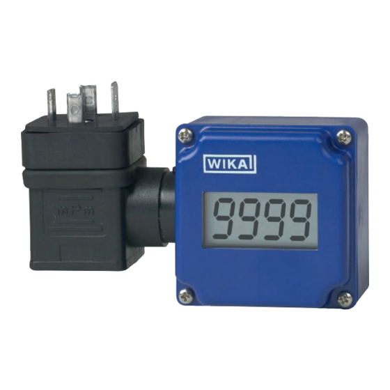
- Seite 1 Operating instructions Betriebsanleitung Attachable indicator model A-IAI-1 Aufsteckanzeige Typ A-IAI-1 Attachable indicator model A-IAI-1...
- Seite 2 3 - 24 Operating instructions model A-IAI-1 Seite 25 - 47 Betriebsanleitung Typ A-IAI-1 © 2012 WIKA Alexander Wiegand SE & Co. KG All rights reserved. / Alle Rechte vorbehalten. ® WIKA is a registered trademark in various countries. ®...
-
Seite 3: Inhaltsverzeichnis
5.3 Configuration of the display 6. Faults 7. Maintenance and cleaning 7.1 Maintenance 7.2 Cleaning 8. Dismounting, return and disposal 8.1 Dismounting 8.2 Return 8.3 Disposal 9. Specifications Annex 1: EU declaration of conformity WIKA operating instructions attachable indicator model A-IAI-1... -
Seite 4: General Information
1. General information 1. General information The model A-IAI-1 attachable indicator described in the operating ■ instructions has been manufactured using state-of-the-art technology. All components are subject to stringent quality and environmental criteria during production. Our management systems are certified to ISO 9001 and ISO 14001. -
Seite 5: Design And Function
The display of the measured value is made on a 4-digit LC display with a maximum indication range of -1999 ... 9999 digits. The model A-IAI-1 attachable indicator is suitable for use in hazardous areas in accordance with: II 2G Ex ia IIC/IIB T4 Gb or II 2G Ex ib IIC/IIB T4 Gb The A-IAI-1 has been designed for the connection of any intrinsically safe transmitter (with 4 ... -
Seite 6: Safety
WARNING! ... indicates a potentially dangerous situation in the hazardous area that can result in serious injury or death, if not avoided. WIKA operating instructions attachable indicator model A-IAI-1... -
Seite 7: Intended Use
3. Safety 3.2 Intended use The model A-IAI-1 attachable indicator is suitable for insertion between an intrinsically safe transmitter and the corresponding output connector (angular connector). The instrument has been designed and built solely for the intended use described here, and may only be used accordingly. The technical specifica- tions contained in these operating instructions must be observed. -
Seite 8: Additional Safety Instructions For Instruments Per Atex
1. No repairs or alterations may be carried out on the instru- ment by the customer. For maintenance or repair, the instru- ment must be returned to the manufacturer. 2. Opening the instrument is only permitted outside of the Ex area. WIKA operating instructions attachable indicator model A-IAI-1... -
Seite 9: Special Hazards
The trouble-free function and operational safety of the instru- ment can only be guaranteed if the general safety measures and the instrument-specific safety instructions given in this manual are followed. WIKA operating instructions attachable indicator model A-IAI-1... - Seite 10 ■ has been stored under unsuitable conditions for an extended period of time. ■ If there is any doubt, please return the instrument to the manufacturer for repair or maintenance. WIKA operating instructions attachable indicator model A-IAI-1...
-
Seite 11: Labelling, Safety Marks
3.7 Ex marking ATEX IECEx II 2 G Ex ia IIC/IIB T4 Gb II 2 G Ex ib IIC/IIB T4 Gb EC-type examination certificate EPS 21 ATEX 1 036 X WIKA operating instructions attachable indicator model A-IAI-1... -
Seite 12: Transport, Packaging And Storage
2. Place the instrument, along with shock-absorbent material, in the packaging. 3. If stored for a prolonged period of time (more than 30 days), place a bag containing a desiccant inside the packaging. WIKA operating instructions attachable indicator model A-IAI-1... -
Seite 13: Commissioning, Operation
Since this assignment is not standardised, it can happen that the assignment for the connected trans- mitter does not match the assignment of the attachable indicator. Standard assignment for the model A-IAI-1 angular connector Contact number Wiring colour Pin Female con-... -
Seite 14: Configuration Of The Display
In the angular connector, pin contact 2 is directly connected (1:1) with the Pin contacts female contact. Between pin contact 1 (+) and female contact 1 (-) is the A-IAI-1. Pin contact 3 and 4 are also connected 1:1 with the female connec- tor. Female connector... - Seite 15 Operating keys Key 1: Calling menu options and saving settings Key 2: Increasing the parameter values Key 3: Decreasing the parameter values Key 3 Key 1 Key 2 WIKA operating instructions attachable indicator model A-IAI-1...
- Seite 16 This value will be displayed when the input signal = 4 mA di.Hi Upper indication range limit (display high) -1999 ... 9999 This value will be displayed when the input signal = 20 mA WIKA operating instructions attachable indicator model A-IAI-1...
- Seite 17 Filter deactivated 0.1 ... 2.0 Activate the filter in order to prevent the display from “jumping” with every small fluctuation and to suppress single spikes. The larger the number, the stronger the filtering. WIKA operating instructions attachable indicator model A-IAI-1...
- Seite 18 0 bar = 0.08, at 20 bar = 20.02 From this is calculated: Zero point: 0.08 Slope: 20.02 – 0.08 = 19.94 Deviation: 0.06 = set slope - actual slope = 20.00 – 19.94 WIKA operating instructions attachable indicator model A-IAI-1...
-
Seite 19: Faults
The error message will reset Faulty connection itself as soon as the input Measuring range exceeded signal is once more within the permissible limits. Check the transmitter and the instrument configuration (e.g. input signal). WIKA operating instructions attachable indicator model A-IAI-1... - Seite 20 Ensure that pressure or signal is no longer present and protect against accidental commissioning. ▶ Contact the manufacturer. ▶ If a return is needed, please follow the instructions given in chapter 8.2 “Return”. WIKA operating instructions attachable indicator model A-IAI-1...
-
Seite 21: Maintenance And Cleaning
Remove the plug and the attachable indicator. Then replace the angular connector onto the transmitter and secure it. For this, use the screw originally supplied with the transmitter, it is shorter. WIKA operating instructions attachable indicator model A-IAI-1... -
Seite 22: Return
8. Dismounting, return and disposal 8.2 Return Strictly observe the following when shipping the instrument: All instruments delivered to WIKA must be free from any kind of hazardous substances (acids, bases, solutions, etc.) and must therefore be cleaned before being returned. -
Seite 23: Specifications
90 x 50.5 x 39.5 mm (without angular connector) Weight approx. 80 g Permissible ambient conditions Operating temperature -20 ... +50 °C Storage temperature -20 ... +50 °C Relative humidity < 80 % r. h. non-condensing WIKA operating instructions attachable indicator model A-IAI-1... - Seite 24 = 1,200 mW < 13 nF Maximum effective internal capacitance Maximum effective internal negligibly small inductance For further specifications see WIKA data sheet AC 80.07 and the order documentation. Dimensions in mm WIKA operating instructions attachable indicator model A-IAI-1...
- Seite 25 5.1 Elektrischer Anschluss 5.2 Anschlussbelegung 5.3 Konfiguration der Anzeige 6. Störungen 7. Wartung und Reinigung 7.1 Wartung 7.2 Reinigung 8. Demontage, Rücksendung und Entsorgung 8.1 Demontage 8.2 Rücksendung 8.3 Entsorgung 9. Technische Daten Anlage 1: EU-Konformitätserklärung WIKA Betriebsanleitung Aufsteckanzeige Typ A-IAI-1...
-
Seite 26: Allgemeines
1. Allgemeines 1. Allgemeines Die in der Betriebsanleitung beschriebene Aufsteckanzeige Typ A-IAI-1 wird ■ nach den neuesten Erkenntnissen gefertigt. Alle Komponenten unterliegen während der Fertigung strengen Qualitäts- und Umweltkriterien. Unsere Managementsysteme sind nach ISO 9001 und ISO 14001 zertifiziert. Diese Betriebsanleitung gibt wichtige Hinweise zum Umgang mit dem ■... -
Seite 27: Aufbau Und Funktion
Anzeige des Messwertes erfolgt auf einem 4-stelligen LC-Display mit einem maximalen Display-Anzeigebereich von -1999 ... 9999 Digit. Die Aufsteckanzeige Typ A-IAI-1 ist geeignet für den Einsatz in explosionsge- fährdeten Bereichen gemäß: II 2G Ex ia IIC/IIB T4 Gb bzw. II 2G Ex ib IIC/IIB T4 Gb Die A-IAI-1 ist für den Anschluss beliebiger eigensicherer Messumformer... -
Seite 28: Sicherheit
Nichtbeachtung der Sicherheitshinweise besteht die Gefahr schwerer oder tödlicher Verletzungen. WARNUNG! … weist auf eine möglicherweise gefährliche Situation im explo- sionsgefährdeten Bereich hin, die zum Tod oder zu schweren Verletzungen führen kann, wenn sie nicht gemieden wird. WIKA Betriebsanleitung Aufsteckanzeige Typ A-IAI-1... -
Seite 29: Bestimmungsgemäße Verwendung
3. Sicherheit 3.2 Bestimmungsgemäße Verwendung Die Aufsteckanzeige Typ A-IAI-1 ist zum Zwischenstecken zwischen einem eigensicheren Transmitter und dem dazugehörigen Ausgangsstecker (Winkelstecker) geeignet. Das Gerät ist ausschließlich für den hier beschriebenen bestimmungsge- mäßen Verwendungszweck konzipiert und konstruiert und darf nur dement- sprechend verwendet werden. -
Seite 30: Zusätzliche Sicherheitshinweise Für Geräte Nach Atex
1. Es dürfen am Gerät keine Veränderungen oder Repara- turen vom Kunden vorgenommen werden. Zur Wartung oder Reparatur muss das Gerät zum Hersteller eingesandt werden. 2. Das Öffnen des Gerätes ist nur außerhalb des Ex-Raumes zulässig. WIKA Betriebsanleitung Aufsteckanzeige Typ A-IAI-1... -
Seite 31: Besondere Gefahren
Lebensgefahr. Einbau und Montage des Gerätes dürfen nur durch Fachperso- nal erfolgen. WARNUNG! Dieses Gerät nicht in Sicherheits- oder in Not-Aus-Einrich- tungen benutzen. Fehlerhafte Anwendungen des Gerätes können zu Verletzungen oder materiellen Schäden führen. WIKA Betriebsanleitung Aufsteckanzeige Typ A-IAI-1... - Seite 32 Anlage kann durch das Gerät beeinträchtigt sein, wenn es z. B.: sichtbare Schäden aufweist. ■ nicht mehr wie vorgeschrieben arbeitet. ■ längere Zeit unter ungeeigneten Bedingungen gelagert wurde. ■ In Zweifelsfällen das Gerät grundsätzlich an den Hersteller zur Reparatur bzw. Wartung einschicken. WIKA Betriebsanleitung Aufsteckanzeige Typ A-IAI-1...
-
Seite 33: Beschilderung, Sicherheitskennzeichnungen
Vor Montage und Inbetriebnahme des Gerätes unbedingt die Betriebsanleitung lesen! 3.7 Ex-Kennzeichnung ATEX IECEx II 2 G Ex ia IIC/IIB T4 Gb II 2 G Ex ib IIC/IIB T4 Gb EG-Baumusterprüfbescheinigung EPS 21 ATEX 1 036 X WIKA Betriebsanleitung Aufsteckanzeige Typ A-IAI-1... -
Seite 34: Transport, Verpackung Und Lagerung
Gerät wie folgt verpacken und lagern: 1. Das Gerät in eine antistatische Plastikfolie einhüllen. 2. Das Gerät mit dem Dämmmaterial in der Verpackung platzieren. 3. Bei längerer Einlagerung (mehr als 30 Tage) einen Beutel mit Trocknungs- mittel der Verpackung beilegen. WIKA Betriebsanleitung Aufsteckanzeige Typ A-IAI-1... -
Seite 35: Inbetriebnahme, Betrieb
Die Winkelsteckerbelegung ist auf die gebräuchlichste Belegung des jewei- ligen Eingangssignals ausgelegt. Da diese Belegung jedoch nicht genormt ist, kann es vorkommen, dass die Belegung des anzuschließenden Transmit- ters nicht mit der Belegung der Aufsteckanzeige übereinstimmt. Standard-Belegung des Winkelsteckers Typ A-IAI-1 Kontaktnummer Adernfarbe Stift Buchse... - Seite 36 5. Inbetriebnahme, Betrieb Stiftkontakte Im Winkelstecker ist der Stiftkontakt 2 direkt 1:1 mit der Buchse verbunden. Zwischen Stiftkontakt 1 (+) und Buchsenkontakt 1 (-) befindet sich die A-IAI-1. Die Stiftkontakte 3 und 4 werden ebenfalls 1:1 mit der Buchse verbunden. Buchse Hat der anzuschließende Transmitter den negativen Versorgungsanschluss...
-
Seite 37: Konfiguration Der Anzeige
Die Konfiguration erfolgt mittels dieser Tasten, sodass das Gehäuse nicht geöffnet werden muss. Bedientasten: Taste 1: Aufrufen von Menüpunkten und Speichern von Einstellungen Taste 2: Erhöhen der Parameterwerte Taste 3: Erniedrigen der Parameterwerte Taste 3 Taste 1 Taste 2 WIKA Betriebsanleitung Aufsteckanzeige Typ A-IAI-1... -
Seite 38: Bedeutung
■ des Parameters erscheint im Display. Wird bei der Eingabe länger als 60 Sekunden keine Taste gedrückt, so wird die Konfiguration des Gerätes abgebrochen. Bereits gespeicherte Werte gehen nicht verloren. Parameter der Aufsteckanzeige Typ A-IAI-1 Parameter Werte Bedeutung Taste 1... - Seite 39 Die Messgrenzen liegen bei ca. 3,7 und 20,8 mA. FiLt Filter (filter) Filter deaktiviert 0.1 ... 2.0 Filter aktiviert, um das „Springen“ der Anzeige bei kleinsten Änderungen zu vermeiden und um einzelne Störimpulse zu unterdrücken. Größere Zahlen bedeuten stärkere Filterung. WIKA Betriebsanleitung Aufsteckanzeige Typ A-IAI-1...
- Seite 40 Die Geräteanzeige ohne Offset und Steigungskorrektur ist wie folgt: bei 0 bar = 0,08, bei 20 bar = 20,02 Hieraus errechnet sich: Nullpunkt: 0,08 Steigung: 20,02 – 0,08 = 19,94 Abweichung: 0,06 = Soll-Steigung - Ist-Steigung = 20,00 – 19,94 WIKA Betriebsanleitung Aufsteckanzeige Typ A-IAI-1...
-
Seite 41: Störungen
Folgende Fehlercodes sind definiert: Fehler Ursachen Maßnahmen Err.1 Eingangssignal zu groß Die Fehlermeldung wird Messbereich Fehlanschluss zurückgesetzt, sobald das überschritten Eingangssignal wieder innerhalb der zugelassenen Grenzen liegt. Messumformer und Geräte- konfiguration überprüfen (z. B. Eingangssignal). WIKA Betriebsanleitung Aufsteckanzeige Typ A-IAI-1... - Seite 42 Aufsteckanzeige unverzüglich außer Betrieb setzen. ▶ Sicherstellen, dass kein Druck bzw. Signal mehr anliegt und gegen versehentliche Inbetriebnahme schützen. ▶ Kontakt mit dem Hersteller aufnehmen. ▶ Bei notwendiger Rücksendung die Hinweise unter Kapitel 8.2 „Rücksendung“ beachten. WIKA Betriebsanleitung Aufsteckanzeige Typ A-IAI-1...
-
Seite 43: Wartung Und Reinigung
Zunächst die Stromversorgung trennen, anschließend die Winkelschraube, mit der Winkelstecker, Aufsteckanzeige und Transmitter verbunden sind, lösen. Stecker und Aufsteckanzeige entfernen. Danach Winkelstecker wieder auf den Transmitter aufstecken und festschrauben. Hierzu die Schaube aus dem Originalzubehör des Transmitters verwenden, diese ist kürzer. WIKA Betriebsanleitung Aufsteckanzeige Typ A-IAI-1... -
Seite 44: Rücksendung
8. Demontage, Rücksendung und Entsorgung 8.2 Rücksendung Beim Versand des Gerätes unbedingt beachten: Alle an WIKA gelieferten Geräte müssen frei von Gefahrstoffen (Säuren, Laugen, Lösungen, etc.) sein und sind daher vor der Rücksendung zu reinigen. Zur Rücksendung des Gerätes die Originalverpackung oder eine geeignete Transportverpackung verwenden. -
Seite 45: Technische Daten
90 x 50,5 x 39,5 mm (ohne Winkelstecker) Gewicht ca. 80 g Zulässige Umgebungsbedingungen Betriebstemperatur -20 ... +50 °C Lagertemperatur -20 ... +50 °C Relative Luftfeuchte < 80 % r. F. nicht kondensierend Temperatureinfluss auf die 0,1 % / 10 K Anzeige WIKA Betriebsanleitung Aufsteckanzeige Typ A-IAI-1... - Seite 46 = 100 mA Leistungsbeschränkung i = 1.200 mW < 13 nF Maximale wirksame innere Kapazität Maximale wirksame innere vernachlässigbar klein Induktivität Weitere technische Daten siehe WIKA Datenblatt AC 80.07 und Bestellunterlagen. Abmessungen in mm WIKA Betriebsanleitung Aufsteckanzeige Typ A-IAI-1...
-
Seite 47: Annex 1: Eu Declaration Of Conformity
Annex 1: EU declaration of conformity Anlage 1: EU-Konformitätserklärung WIKA Betriebsanleitung Aufsteckanzeige Typ A-IAI-1... - Seite 48 WIKA subsidiaries worldwide can be found online at www.wika.com. WIKA Niederlassungen weltweit finden Sie online unter www.wika.de. WIKA Alexander Wiegand SE & Co. KG Alexander-Wiegand-Strasse 30 63911 Klingenberg • Germany Tel. +49 9372 132-0 Fax +49 9372 132-406 info@wika.de www.wika.de...