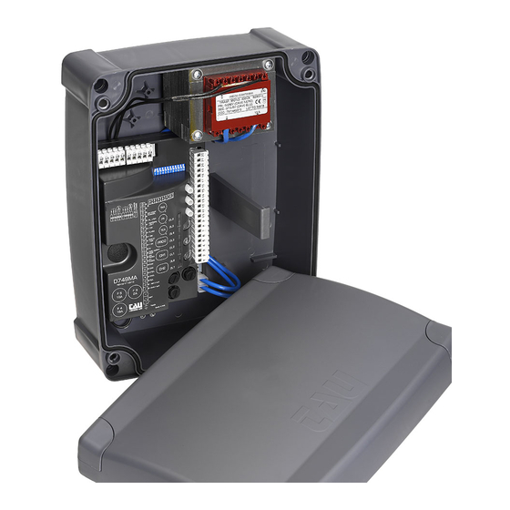
Herunterladen Inhalt Inhalt Diese Seite drucken
tau D749MA-R Installationsanleitung
Vorschau ausblenden Andere Handbücher für D749MA-R:

Werbung

Verfügbare Sprachen
  • DE

Verfügbare Sprachen

  • DEUTSCH, seite 25
GUIDA ALL'INSTALLAZIONE
INSTALLATION GUIDE
INSTALLATIONSANLEITUNG
NOTICE D'INSTALLATION
GUÍA PARA LA INSTALACIÓN
GUIA DE INSTALAÇÃO
D749MA-R
IT - Istruzioni originali

Werbung

Inhaltsverzeichnis
loading

Inhaltszusammenfassung für tau D749MA-R

  • Seite 1 GUIDA ALL’INSTALLAZIONE INSTALLATION GUIDE INSTALLATIONSANLEITUNG NOTICE D’INSTALLATION GUÍA PARA LA INSTALACIÓN GUIA DE INSTALAÇÃO D749MA-R IT - Istruzioni originali...
  • Seite 2 SCHEMA D749MA-R SCHALTPLAN SCHÉMA ESQUEMA DEL ESQUEMA CABLAGGIO WIRING CÂBLAGE CABLEADO DE LIGAÇÕES D749MA-R DIAGRAM D749MA-R D749MA-R D749MA-R D749MA-R Dip-switches 9 10 11 12 9 10 11 12 D749MA-R FIXED SAFETY EDGE PROG EXT. PHOTO INT. PHOTO STOP OPEN/CLOSE PEDESTRIAN 3.15A...
  • Seite 3 - Morsetti 1 - 2: Attenzione a NON invertire la polarità. - Se il jumper 6 non è inserito, verrà attivata la modalità basso consumo e, al termine di ogni manovra, le uscite 11-12, 12-13, 14-15, 16-17 e 16-18 verranno spente. - Terminals 1 –...
  • Seite 4: Installazione

    Il presente manuale è destinato solamente al personale tecnico qualificato per l’installazione. Nessuna informazione contenuta nel presente fascicolo può essere considerata d’interesse per l’utilizzatore finale. Questo manuale è allegato alla centralina D749MA-R; non deve pertanto essere utilizzato per prodotti diversi! Avvertenze importanti: Togliere l’alimentazione di rete alla scheda prima di accedervi.
  • Seite 5: Caratteristiche Tecniche

    TAU cod. M-03000010CO per il collegamento dei motori alla centrale di comando. In caso di lunghi tratti di cavi ( > 20 m) per i comandi N.A. / N.C. (es: APRE/CHIUDE, STOP, PEDONALE, ecc), al fine di evitare malfunzionamenti del cancello si renderà...
  • Seite 6 ingresso N.A. pulsante PEDONALE - Comanda l’apertura e la chiusura 3 - 6 PEDONALE totale del motore 1 (M1) ed è regolato nel funzionamento dai dip- switches 2 e 4. (3= PED - 6= COM) ingresso N.A. pulsante APRE/CHIUDE - Comanda l’apertura e la chiusura 4 - 6 APRE/CHIUDE dell’automazione ed è...
  • Seite 7 ingresso antenna radioricevente ad innesto solo per ricevitori 433,92 21 - 22 ANTENNA MHz. (21= MASSA - 22= SEGNALE) uscita alimentazione motore (M2) 24V DC max 50 W. 23 - 24 MOTORE (M2) (23= POSITIVO - 24= NEGATIVO) alimentazione e ingresso encoder (25= BIANCO segnale - 26= BLU 25 - 26 - 27 ENCODER (M2) negativo - 27= MARRONE positivo)
  • Seite 8: Procedura Di Memorizzazione

    l’automazione ignora i comandi di chiusura durante l’apertura e il tempo di pausa. NO REVERSE l’automazione si comporta come stabilito dal dip switch nr. 2. la funzione prelampeggio è inserita. PRE- LAMPEGGIO la funzione prelampeggio è disinserita. la funzione “verifica delle fotocellule” è inserita. FOTOTEST la funzione “verifica delle fotocellule”...
  • Seite 9 Accertarsi pertanto di non sostare nelle vicinanze dell’automazione durante la procedura di memorizzazione. 7. CARATTERISTICHE DELLA D749MA-R APERTURA E CHIUSURA COMANDATA DA OROLOGIO É possibile comandare l’apertura e la chiusura dell’automazione mediante un orologio digitale che in uscita disponga di un contatto pulito N.A.
  • Seite 10 DL6 - Verde led di segnalazione BORDO SENSIBILE LED - DL7 Il led DL7, oltre ad indicare la presenza della batteria, segnala eventuali errori con una serie di lampeggi predefiniti di diversi colori: Legenda: led acceso fisso; led lampeggiante; batteria carica, tensione di rete presente; sempre acceso (Verde): batteria in carica;...
  • Seite 11 superamento limite max. di corrente motore 1; 5 lampeggi (Rosso): Picco di eccessivo assorbimento del motoriduttore, controllare l’assenza di ostacoli lungo la corsa dell’automazione, verificare l’assorbimento di corrente del motore a vuoto e applicato alla chiusura; superamento limite max. di corrente motore 2; 5 lampeggi (Giallo): Picco di eccessivo assorbimento del motoriduttore, controllare l’as- senza di ostacoli lungo la corsa dell’automazione, verificare l’assor-...
  • Seite 12 • se il ripristino avviene dopo un intervento manuale (senza interruzioni all’alimentazione della scheda), saranno necessarie 4 o 5 manovre complete per fare riallineare l’automazione, durante le quali non verranno osservati i normali rallentamenti e le conseguenti battute d’arresto. 10. RADIO RICEVITORE 433,92 MHz INTEGRATO Il radio ricevitore può...
  • Seite 13 24 per M2). 12. GARANZIA: CONDIZIONI GENERALI La garanzia della TAU ha durata di 24 mesi dalla data di acquisto dei prodotti (fa fede il documento fiscale di vendita, scontrino o fattura). La garanzia comprende la riparazione con sostituzione gratuita (franco sede TAU: spese di imballo e di...
  • Seite 14 Qualora il guasto sia determinato da un impianto non eseguito secondo le istruzioni fornite dall’azienda all’interno di ogni confezione. • Qualora non siano stati impiegati tutti componenti originali TAU per l’installazione dell’automa- tismo. • Qualora i danni siano causati da calamità naturali, manomissioni, sovraccarico di tensione, alimentazione non corretta, riparazioni improprie, errata installazione, o altre cause non impu- tabili alla TAU.
  • Seite 15: Installation

    This manual is designed to assist qualified installation personnel only. It contains no information that may be of interest to final users. This manual is attached to the D749MA-R control unit, therefore it may not be used for different products! Important warnings: Disconnect the mains power supply to the board before accessing it.
  • Seite 16: Technical Characteristics

    TAU cable code M-03000010C0 to connect the motors to the control board. In case of long sections of cables (> 20 m) for N.O./N.C. controls (e.g. OPEN / CLOSE, STOP, PEDESTRIAN, etc.), in order to avoid gate malfunctions, it will be necessary to uncouple the...
  • Seite 17 STOP button N.C. input – Stops the automation in any position, temporarily 5 - 6 STOP preventing the automatic closure, if programmed. Bridge the connectors if not used. (5= STOP - 6= COM ) PHOTOCELL OR SAFETY DEVICE input INSIDE the automation (Normally Closed contact).
  • Seite 18 If Jumper J6 is not plugged in, energy saving mode will be activated and, at the end of each manouvre, outputs 11-12, 12-13, 14-15, 16-17 and 16-18 will be switched off. IMPORTANT: • Do not connect auxiliary relays or other devices tot he 18 V DC output (terminals 11 – 12) to avoid malfunctions of the control unit.
  • Seite 19: Memorization Procedure

    Please remember that an obstacle during saving is interpreted as a mechanical limit stop (the system does not start any safety operation, it just stops the motors). Make sure you don’t stand near the automation during saving. 7. D749MA-R CHARACTERISTICS...
  • Seite 20: Diagnostics Led

    TIMER-OPERATED OPENING AND CLOSING CYCLES The opening/closing of the automation can be controlled by means of a timer that has a free N.O. output contact (relay). The timer must be connected to terminals 4 - 6 (OPEN/CLOSE button) and can be programmed so that, at the desired opening time, the relay contact closes until the desired closing time (when the timer’s relay contact opens, enabling the automatic closing of the gate).
  • Seite 21 saving in progress; fast flashing (yellow): phototest error 1 flash (red): Disable phototest (dip-switch 6 OFF), check the operation of the photocells and their connection; unknown status, next operation REALIGNMENT; 1 flash (yellow): obstacle for motor 1; 2 flashes (red): Make sure there are no obstacles across the path of the automation and that it slides smoothly;...
  • Seite 22 When LEDs DL7 and DL8 flash at the same time they indicate: factory reset procedure waiting for confirmation; flashing (red + red): waiting for total cancellation of the radio channels; flashing (yellow + yellow): Multiple errors are signalled by a 2-second pause between signals. Should the encoder (obstacle detection) activates while closing, the controller will reverse the direction and slowly open until the laef reaches its fully opened position.
  • Seite 23 7_ to exit the learning mode without memorising a code, press button CH1 or CH2 briefly. MEMORY CAPACITY The code memory capacity* of the D749MA-R can be expanded from 86 to 126, 254 or 1022 codes (trans- mitters) by replacing the memory cards as follows (plug them onto J3 connector, see wiring diagram): codes Art.
  • Seite 24 This guarantee covers the repair or replacement at TAU’s expense (ex-works TAU: packing and trans- port at the customer’s expense) of parts that TAU recognises as being faulty as regards workmanship or materials. For visits to the customer’s facilities, also during the guarantee period, a “Call-out fee” will be charged for travelling expenses and labour costs.
  • Seite 25: Steuerplatine Für Einen (Zwei) 24V Motor(En) Mit Encoder

    Das vorliegende Handbuch ist nur für technisches, zur Installation qualifiziertes Personal bestimmt. Die im vorliegenden Heft enthaltenen Informationen sind für den Endbenutzer nicht interessant. Diese An- leitung liegt der Steuerung D749MA-R bei und darf daher nicht für andere Produkte verwendet werden! Wichtige Hinweise: Vor Eingriffen an der Steuerkarte die Netzstromversorgung abtrennen.
  • Seite 26: Technische Merkmale

    Steuerungen über die RELAIS zu trennen oder unsere Vorrichtung 750T RELE zu nutzen. 2. EINFÜHRUNG Die Karte D749MA-R kann mit zwei verschiedenen Betriebsweisen arbeiten, wählbar mit dem Jumper J6 (siehe Verkabelungsplan). J6 Gebrückt: Modalität Standard, das heißt, das Steuergerät ist immer gespeist;...
  • Seite 27 (siehe Hinweis am Ende des Absatzes). 2. FUNKKANAL ACHTUNG: Der Default-Ausgang ist monostabil an für 2 Sek. Zur Um- schaltung auf bistabil aktiv oder zur Änderung der Aktivierungszeit muss die Programmierung mit dem Handprogrammiergerät TAU- PROG vorgenommen werden (siehe entsprechende Anweisungen).
  • Seite 28: Einstellung Der Logik

    Eingang für steckbare Funkempfängerantenne, nur für 433,92 MHz Emp- 21 - 22 ANTENNE fänger. (21= MASSE - 22= SIGNAL) Ausgang Motorversorgung 24V DC max. 50 W. 23 - 24 MOTOR (M2) (23= PLUS - 24= MINUS) Versorgung und Encodereingang (25= WEIß Signal - 26= BLAU minus - 27= 25 - 26 - 27 ENCODER (M2) BRAUN plus) Ausgang Motorversorgung 24V DC max.
  • Seite 29: Speicherverfahren

    die Vorwarnfunktion ist eingeschaltet. VORWARN- FUNKTION die Vorwarnfunktion ist abgeschaltet. die Funktion „Fotozellentest“ ist eingeschaltet. die Funktion „Fotozellentest“ ist abgeschaltet. FOTOTEST Hinweis. Auf OFF lassen, wenn die Lichtschranken nicht verwendet werden. die Funktion “Druckstoß” ist eingeschaltet. Sie ermöglicht das Ausspan- nen des Elektroschlosses (nur verwenden, falls das Elektroschloss vor- DRUCKSTOSS handen ist);...
  • Seite 30: Diagnose-Leds

    Halten Sie sich daher während des Abspeicherungsverfahrens nicht in der Nähe der Automatisierung auf. 7. MERKMALE DER SCHALT- UND STEUERTAFEL D749MA-R ÖFFNUNG UND SCHLIEßUNG MIT ZEITUHR Die Öffnung und Schließung der Automatisierung kann über eine digitale Uhr gesteuert werden, die im Ausgang über einen potentialfreien NO-Kontakt (Relais) verfügt.
  • Seite 31 1 Aufblinken alle 4 Sekunden: Batterie geladen, keine Netzspannung vorhanden; (grün) Kontrollieren Sie die Netzstromversorgung; Stromversorgung mit Photovoltaik-Modul (Klemmen 1-2), 1 Aufblinken alle 4 Sekunden: Ladegerät deaktiviert (gelb) 1 Aufblinken alle 2 Sekunden: Batterie leer; (rot) Batterie laden, Batterie ersetzen; Batterie defekt; Schnelles Aufblinken (rot): Batterie ersetzen; LED - DL8 Die LED DL8 zeigt eventuelle Störungen der Logik der Karte durch Aufblinken in verschiedenen Farben an: Zeichenerklärung:...
  • Seite 32: Rückstellung Automatischer Betrieb

    Zu hohe Stromaufnahme des Getriebemotors, stellen Sie sicher, dass keine Hindernisse auf dem Weg der Automatisierung vor- handen sind, überprüfen Sie die Stromaufnahme der Motors im Leerlauf und angebracht an die Tor; automatische Schließung deaktiviert nach 5 fehlgeschla- 6 Aufblinken (rot): genen Eingriffen in Folge;...
  • Seite 33: Eingebauter 433,92 Mhz Funkempfänger

    bei denen die normalen Verlangsamungen und folglich die Stopp-Anschläge nicht beachtet werden. 10. EINGEBAUTER 433,92 MHz FUNKEMPFÄNGER Der Funkempfänger kann bis zu max. 86 Rolling Codes (BUG2R, BUG4R, K-SLIM-RP, T-4RP) erlernen, die beliebig an den beiden Kanälen einzustellen sind. Der erste Kanal steuert die Steuerkarte zur Öffnung der Automatisierung direkt, der zweite Kanal steuert ein Relais für einen im Ausgang potentialfreien NO-Kontakt (Klemmen Nr.
  • Seite 34 Auf der Steuerplatine D749MA-R kann der Speicher* von 86 bis zu 126, 254 oder 1022 Codes (Hand- sender) erweitert werden, indem die Speicherkarten wie angegeben ersetzt wird (Speicherkarte in den dafür vorgesehenen Slot J3 einstecken – siehe Kabelplan): Codes Art.
  • Seite 35 Defekt durch eine Installation verursacht ist, die nicht nach den in jeder Packung enthalte- nen Herstelleranweisungen erfolgte. • wenn für die Installation der Vorrichtung auch andere Teile als Original-TAU-Komponenten verwen- det wurden. • wenn die Schäden durch Naturkatastrophen, Handhabungen, Spannungsüberlasten, unkorrekte Versorgung, unsachgemäße Reparaturen, falsche Installation oder sonstiges, für das die Firma TAU...
  • Seite 36 Le présent manuel est destiné exclusivement au personnel technique qualifié pour l’installation. Au- cune information contenue dans ce fascicule ne peut être considérée comme intéressante pour l’uti- lisateur final. Ce manuel est joint à la logique de commande D749MA-R, il ne doit donc pas être utilisé pour des produits différents ! Recommandations importantes : Couper l’alimentation électrique de la carte avant d’y accéder.
  • Seite 37: Caractéristiques Techniques

    OUVRE/FERME, STOP, PIETON etc.) et pour éviter un mauvais fonctionnement du portail, nous conseillons d’utiliser un relais pour découpler les commandes (modèle relais TAU 750T-RELE). 2. INTRODUCTION La fiche D749MA-R peut fonctionner en deux modalités différents, sélectionnables par pontet J6 (voir schéma de câblage). J6 pontés: modalité...
  • Seite 38 entrée N.F. touche STOP – Arrête l’automatisme quelle que soit sa position, 5 - 6 en inhibant momentanément la fermeture automatique, si elle est pro- STOP grammée. Mettre en pont les bornes si non utilisées. (5 = STOP - 6 = COM) entrée PHOTOCELLULES ou DISPOSITIFS DE SÉCURITÉ...
  • Seite 39 alimentation et entrée encodeur (30= BLANC signal - 31= BLEU négatif 30 - 31 - 32 ENCODEUR (M1) - 32= MARRON positif) * Les sorties sont configurables avec TAUPROG (voir instructions relatives). Le tableau indique les configurations standards. Si le cavalier J6 n’est pas inséré, la fonction modalité consommation réduite sera activée et, à la fin de chaque manœuvre, les sorties 11-12, 12-13, 14-15, 16-17 e 16-18 seront désactivées.
  • Seite 40: Procédure De Mémorisation

    “RÉGLAGES DE FABRIQUE“ (voir page 46). BORD SENSIBLE RESISTIF (étau n ° 10). BORD CÔTE FIXE (contact NC - étau n ° 10). SENSIBLE Remarque: s’il n’est pas utilisé, maintenir le dip sur OFF. 6. PROCÉDURE DE MÉMORISATION ATTENTION : Après avoir alimenté...
  • Seite 41 Par conséquent, assu- rez-vous de ne pas rester au prés de l’automatisme pendant la procédure de stockage. 7. CARACTÉRISTIQUES DE LA D749MA-R OUVERTURE ET FERMETURE COMMANDÉE PAR UNE HORLOGE Il est possible de commander l’ouverture et la fermeture de l’automatisme avec une horloge numé- rique disposant en sortie d’un contact N.O.
  • Seite 42 1 clignotement toutes les 4 sec: alimentation par panneau photovoltaïque (bornes 1-2), chargeur de batterie désactivé (jaune) 1 clignotement toutes les 2 sec: batterie déchargé; (rouge) Charger la batterie, remplacez la batterie batterie défectueuse; clignotement rapide (rouge): Remplacez la batterie; LED - DL8 Le led DL8 signale des avertissements/erreurs de la logique de la fiche avec une série prédéfinie de clignotements de différents couleurs:...
  • Seite 43 fermeture automatique désactivée après 5 interven- 6 clignotement (rouge): tions consécutives infructueuses; Pour effectuer la fermeture est nécessaire de donner une impulsion de commande; intervention de sécurité de la barre palpeuse 7 clignotement (rouge): Une impulsion de commande est nécessaire pour la fermeture. erreur de mémoire EEPROM externe 8 clignotement (rouge): Substituer le module de mémoire externe;...
  • Seite 44 CH1 ou la touche CH2. MÉMOIRE DES CODES Pour les logiques de commande D749MA-R, il est possible d’augmenter la mémoire des codes* (émetteurs) de 86 à 126, 254 ou 1022 en remplaçant les cartes de mémoire de la manière indiquée (il faut les brancher dans le connecteur J3, consulter le schéma de câblage):...
  • Seite 45 24 pour le moteur 2). 12. GARANTIE: CONDITIONS GÉNÉRALES La garantie TAU a une durée de 24 mois à compter de la date d’achat des produits (le document fiscal de vente, ticket de caisse ou facture). La garantie comprend la réparation avec remplacement gratuit (départ usine TAU: frais d’emballage et de transport à...
  • Seite 46 à l’intérieur de chaque emballage. • Si l’on n’a pas utilisé que des pièces originales TAU pour l’installation de l’automatisme. • Si les dommages sont causés par des calamités naturelles, des actes de malveillance, une sur- charge de tension, une alimentation électrique incorrecte, des réparations impropres, une ins-...
  • Seite 47: Instalación

    El presente manual está destinado sólo al personal técnico cualificado para la instalación. Las infor- maciones que contiene este fascículo no pueden considerarse de interés para el usuario final. Este manual se adjunta a la centralina D749MA-R, por lo tanto, no debe utilizarse para productos diversos. Advertencias importantes: Antes de acceder a la tarjeta es necesario desconectarla de la alimentación de red.
  • Seite 48: Características Técnicas

    CIERRA, STOP, PEATONAL, etc.), para evitar un mal funcionamiento de la puerta será necesario desacoplar los diferentes mandos con RELÉS o utilizando nuestro dispositivo 750T-RELE. 2. INTRODUCCIÓN La tarjeta D749MA-R puede funcionar en dos modos diferentes que se seleccionan con el puente J6 (véase el diagrama de cableado). J6 Puenteado: modalidad estándar, es decir la central siempre está...
  • Seite 49 ATENCIÓN: la salida por defecto es monoestable activa 2 seg. Para cambiar a biestable activa o para modificar el tiempo de activa- ción es necesario operar a través del programador portátil TAU- PROG (véanse las instrucciones correspondientes). entrada antena radiorreceptor de enchufe sólo para receptores 433,92...
  • Seite 50 alimentación y entrada codificador. (25= BLANCO señal - 26= AZUL 25 - 26 - 27 ENCODER (M2) negativo - 27= MARRÓN positivo) salida alimentación motor M1 24V DC máx. 50 W. 28 - 29 MOTOR (M1) (28= POSITIVO - 29= NEGATIVO) alimentación y entrada codificador.
  • Seite 51 la función “verificación de las fotocélulas” está activada. FOTOTEST la función “verificación de las fotocélulas” está desactivada. Nota: dejar en OFF cuando no se usan las fotocélulas. la función “golpe a la apertura” está activada. Permite desenganchar la cerradura GOLPE A LA eléctrica (se puede utilizar sólo si se dispone de cerradura eléctrica);...
  • Seite 52: Led De Diagnóstico

    Por lo tanto, asegúrese de no estar cerca del automatismo durante el proceso de me- morización. 7. CARACTERÍSTICAS DE LA D749MA-R APERTURA Y CIERRE CONTROLADA A TRAVÉS DEL RELOJ Es posible accionar la apertura y el cierre del automatismo con un reloj digital que disponga en la sali- da de un contacto sin tensión N.A.
  • Seite 53 batería descargada; 1 destello (Rojo) cada 2 s: Cargue la batería, sustituya la batería; batería averiada; destello rápido (Rojo): Sustituya la batería; LED - DL8 El LED DL8 señala los avisos/errores de la lógica de la tarjeta con una serie de destellos predetermina- dos de diferentes colores: Leyenda: siempre...
  • Seite 54 Se requiere un impulso de comando para llevar a cabo el cierre; error memoria Eeprom externa; 8 destellos (Rojo): Sustituya el módulo de memoria externa; error datos en Eeprom (interna/externa); 8 destellos (Amarillo): Realice el proceso de RESET DE LA MEMORIA RADIO; Además de los avisos/errores de la parte lógica, el LED DL8 también indica el estado de la central du- rante la memorización de los emisores.
  • Seite 55 CH1 o la tecla CH2. CAPACIDAD MEMORIA Para los panels de mando D749MA-R es posible expandir la memoria de los códigos* de 86 a 126, 254 o 1022 utilizando las tarjetas de memoria como se indica (insertándolas en el conector J3, ver diagra-...
  • Seite 56 1; bornes 23 y 24 por el motor 12. GARANTÍA: CONDICIONES GENERALES La garantía de TAU tiene una cobertura de 24 meses a partir de la fecha de compra de los productos (la fecha válida es la que figura en el comprobante de venta, recibo o factura).
  • Seite 57 Si los daños han sido causados por catástrofes naturales, modificaciones, sobrecargas de ten- sión, alimentación incorrecta, reparaciones inadecuadas, instalación incorrecta u otras causas no imputables a TAU. • Si no se han efectuado los trabajos de mantenimiento periódico por parte de un técnico es- pecializado, según las instrucciones dadas por la empresa que se encuentran en el interior de...
  • Seite 58 Este producto pode unicamente ser instalado e mantido por pessoal qualificado em conformidade com as actuais leis, normas e directivas. Ao conceber os seus produtos a TAU cumpre todos as normas aplicáveis ( por favor consulte a decla- ração de conformidade anexa). É de suprema importância que os instaladores observem escrupulosa- mente as mesmas normas quando instalam o producto.
  • Seite 59 RELAYS ou utilizando o nosso dispositivo 750T-RELE. 2. INTRODUÇÃO A placa D749MA-R possui dois modos de operar, seleccionável através do jumper J6 (ver esquema eléctrico). J6 Ligado modo padrão, i.e. a unidade de controlo está sempre alimentada;...
  • Seite 60 Entrada botão STOP N.F. – para a automação em qualquer posição, 5 - 6 STOP temporariamente impedindo o fecho automático, se programado. Ligar em ponte os bornes que não forem utilizados. (5= STOP - 6= COMUM). Entrada para FOTOCÉLULAS ou DISPOSITIVOS de SEGURANÇA situados na parte interior da automação.
  • Seite 61 Se o jumper J6 não está conectado, ele irá alternar para o modo de baixo consumo de energia e, ao final de cada manobra, as saídas 11-12, 12-13, 14-15, 16-17 e 16-18 serão desligados. IMPORTANTE: Não ligar os relés auxiliares ou outros dispositivos à saída dos 24V DC (terminais 11 – 12) de •...
  • Seite 62 Certifique-se que não está próximo da automação durante a memorização. 7. CARACTERÍSTICAS DA D749MA-R ABERTURA E FECHO CONTROLADOS ATRAVÉS DE TEMPORIZADOR É possível controlar a abertura e o fecho do automatismo com um relógio digital que possua um con-...
  • Seite 63 Será apenas necessário ligá-lo aos bornes (4 – 6 botão abertura / fecho) e programá-lo de modo, a que à hora de abertura desejada, o contacto do relógio se feche até à hora pretendida de fecho (momento no qual o relógio do relé se abre de novo permitindo deste modo de novo o fecho automático). Nota: O novo fecho automático que estar activado (dip-switch nº...
  • Seite 64 estado desconhecido, próxima operação REALINHA- 1 piscar (amarelo): MENTO; obstáculo no motor 1; 2 piscar (vermelho): Controle que não haja obstáculos no percurso da automa- ção e a fluidez do mesmo; obstáculo no motor 2; 2 piscar (amarelo); Controle que não haja obstáculos no percurso da automa- ção e a fluidez do mesmo;...
  • Seite 65 Procedimento de reset de fábrica aguardando por piscando (vermelho + vermelho): confirmação; Aguardando pela anulação total dos canais rádio; piscando (amarelo + amarelo): Múltiplos erros são assinalados por um intervalo de 2 segundos entre um lampejo e o seguinte. Se durante a manobra de fecho o encoder intervém (detecção de obstáculo), o quadro reverte o movimento e passa ao modo lento até...
  • Seite 66 24 para o motor 2). 12. GARANTIA: CONDIÇÕES GERAIS A garantia TAU tem uma duração de 24 meses a contar da data de compra dos produtos (o documento fiscal de venda, recibo ou factura). Esta garantia cobre a reparação ou substituição a espensas TAU (à saída da fábrica: embalagem e trans- porte por conta do cliente) das peças que que apresentem defeitos de fabrico ou material defeituoso...
  • Seite 67 Se a avaria for motivada por uma instalação que não respeita as instruções fornecidas pelo fa- bricante que se encontram dentro de cada embalagem. • Se não foram utilizados sómente peças originais TAU para a instalação do automatismo. • Se os danos forem causados por calamidades naturais, modificações, sobrecargas de tensão, alimentação incorrecta, reparações inadequadas, instalação incorrecta ou outros casos não im-...
  • Seite 68 ITALIANO - VIDEO TUTORIAL ENGLISH - VIDEO TUTORIAL - Come memorizzare un - How to learn a Rolling radiocomando Code trasmitter on Rolling Code su centrali Diamond control boards. Diamond. - Come effettuare l' HARD - How to HARD RESET RESET sulla centrale del the control board of your cancello automatico...

Inhaltsverzeichnis