WAGO EPSITRON Bedienungsanleitung
Vorschau ausblenden
Andere Handbücher für EPSITRON:
- Bedienungsanleitung (4 Seiten) ,
- Bedienungsanleitung (4 Seiten) ,
- Handbuch (48 Seiten)
deutsch /
english
Bedienungsanleitung /
EPSITRON
-PRO-Power
®
Stabilisierte Stromversorgung mit integrierter Kontrolleinheit
Stabilised power supply with integrated control module
Anschluss
T
Um Verwechslungen mit anderen An-
schlüssen zu vermeiden, verwenden Sie
ausschließlich die mitgelieferten Stecker.
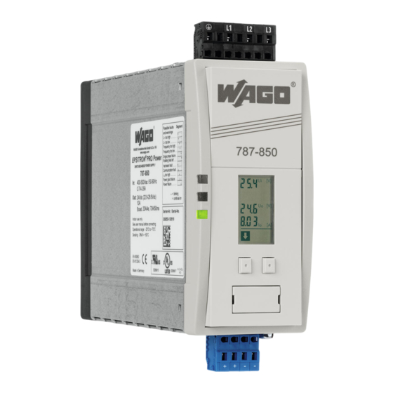
Abbildung zeigt den 787-852
This figure shows the 787-852
Eingang
line
4
PE L1 L2 L3
1
c
b
a
2
3
8
+ + – –
5
Ausgang
load
U
out
S1
S2
S3
8
1 2 3 4 5 6 7 8
S1: geschlossen, wenn Betriebsstundensignalgeber erreicht
closed, if min. one channel tripped
S2: offen, wenn Fehler auftritt
S3: geschlossen, wenn Warnung auftritt
S4: geschlossen, wenn Uout < Power Good
Instruction Manual
787-850
787-852
787-854
Connection
T
To reduce the risk of mistaking the
terminals, the supplied terminals must
be used.
6
7
S4
RxPC TxPC
U
out
Pin 2 = RxPC
Pin 3 = TxPC
Pin 5 = GND
open, if a fault has occurred
closed, if a warning occurrs
closed, if Uout < Power Good
Installation
Installation
Sicherheitsmaßnahmen vor der
Installation
Das Betriebsmittel ist vor unzulässiger
Beanspruchung zu schützen. Insbesonde-
re dürfen bei Transport und Handhabung
keine Bauelemente verbogen und/oder
Isolationsabstände verändert werden.
Die Berührung elektrischer Bauele-
mente und Kontakte ist zu vermeiden.
Das Betriebsmittel immer im span-
nungsfreien Zustand montieren und
verdrahten. Die Produktbeschreibung
und die technischen Hinweise in unserem
Hauptkatalog sowie die Aufschriften am
Betriebsmittel und auf dem Typenschild
sind zu beachten.
Installation
Die Installation ist entsprechend den
örtlichen Gegebenheiten, einschlägigen
Vorschriften (z. B. VDE 0100), nationalen
Unfallverhütungsvorschriften (z. B. UVV-
VBG4 bzw. BGV A3) und den anerkannten
Regeln der Technik durchzuführen. Dieses
elektrische Betriebsmittel ist eine Kom-
ponente, die zum Einbau in elektrische
Anlagen oder Maschinen bestimmt ist
und erfüllt die Anforderungen der Nieder-
spannungsrichtlinie (2006/98/EG). Um
eine ausreichende Konvektion zu gewähr-
leisten, sind folgende Mindestabstände
zu benachbarten Modulen empfohlen:
40mm oben und unten, 10mm auf der
linken und rechten Seite.
Bei Einbau in Maschinen ist die Aufnahme
des bestimmungsgemäßen Betriebes
solange untersagt, bis festgestellt wurde,
dass die Maschine den Bestimmungen
der Maschinenrichtlinie (2006/42/EG)
entspricht.
EN 60204 ist zu beachten. Die Aufnahme
des bestimmungsgemäßen Betriebes
ist nur bei Einhaltung der EMV-Richtlinie
(2004/108/EG) erlaubt. Die Einhaltung
der durch die EMV-Gesetzgebung gefor-
derten Grenzwerte liegt in der Verant-
wortung des Herstellers der Anlage oder
Maschine.
1
LED: Die grüne LED (a) leuchtet,
sofern die Ausgangsspannung größer
als ca. 20,4 Vdc (veränderbarer, werk-
seitiger Power Good Grenzwert) ist.
Die gelbe LED (b) zeigt Warnungen an.
Die rote LED (c) zeigt Fehler an.
2
Display der Kontrolleinheit: Das
Einstellen und Parametrisieren des
Gerätes über das Display wird auf der
Rückseite erklärt.
3
Tasten:Linke Taste = vorwärts im
Menü, rechte Taste = zum Parame-
trisieren.
DIN 35 mm
4
Eingang (schwarzer Stecker) line
rail
5
Ausgang (blauer Stecker) load
6
Montage: Setzen Sie das Gerät mit
der Tragschienenführung an die Ober-
kante der Tragschiene an und rasten
Sie es nach unten ein.
7
Demontage: Ziehen Sie den
Schnappriegel mit Hilfe eines
Schraubendrehers auf und hängen
Sie das Gerät an der Unterkante der
Tragschiene aus.
8
Schnittstelle und Signalausgänge:
Die Schutzkappe ist zur Vermeidung
statischer Entladungen nur unter
Anwendung von ESD-Schutzmaßnah-
men abzunehmen.
Ausgänge, konfigurierbar per PC,
1
Betriebsstundensignalgeber (werk-
seitige Belegung),
3
Warnung,
4
tige Belegung),
onsein- und Ausgänge,
spannung.
Die Schnittstelle ist nicht galvanisch
getrennt. Ein geeignetes Adapter-
kabel (787-890) können Sie optional
über WAGO beziehen. Die optionale
Konfigurationssoftware (759-850)
und die Visualisierungssoftware
(759-851) können Sie kostenlos
unter www.wago.com herunterladen.
Bei Anschluss eines Relais an einen
Signalausgang muss zwingend eine
Freilaufdiode vorhanden sein.
Safety measures before installation
This equipment is to be protected against
improper use. Components are not to
be bent or isolation spacing changed, es-
pecially through handling and transport.
The contact with electrical components
and terminals is to be avoided. Always
disconnect the equipment from the mains
supply, before commencing installation or
wiring. The product description, technical
information in our main catalogue and the
marking on the equipment ratings plate
are to be observed.
Installation
Installation must be carried out accor-
ding to the prevailing local conditions
and safety regulations (e.g. VDE 0100)
national accident prevention regulations
(e.g. UVV-VBG4 or BGV A3) and the ge-
nerally accepted rules of technology. This
equipment is a component designed for
installation into electrical systems and
machines, and fulfils the requirements of
the low voltage guidelines (2006/98/EG).
In order to ensure sufficient convection,
follow installation clearances is recom-
mend: 40mm on top and bottom, 10mm
on the left and right side. When installed
into machinery, the normal operation is
forbidden until it is determined that the
machine fulfils the requirements of the
machinery guidelines (2006/42/EG). EN
60204 must be observed. The EMC re-
quirements (2004/108/EG) must be ful-
filled before operation is commenced. The
observance of the required limitations for
the EMC legislation is the responsibility
of the manufacturer of the installation or
machinery.
1
LED: The green LED (a) lights as soon
as the output voltage is larger than
approx. 20.4 Vdc (changeable, factory
set Power Good level). The yellow LED
(b) shows a warning condition. The red
LED (c) shows a fault condition.
2
The control unit display: The
parameter adjustments are
described on the back of this leaflet.
3
Buttons: Left button = forward in
the menu, right button = to alter
parameter settings.
4
Input (black plug) line
5
Output (blue plug) load
6
Mounting: Place the unit with the DIN
rail guide on the upper edge of the DIN
rail, and snap it in with a
downward motion.
7
Removing: Pull the snap lever open
with the aid of a screwdriver and slide
the unit out at the lower edge of the
DIN rail.
8
Interface and output signal port:
The protective cap is to reduce the
risk of static discharge and should
only be removed with the use of ESD
protective measures.
connections that can be configured
14
Frei belegbare
per PC,
(factory set),
4
Power Good (factory set),
2
Fehler,
568
Power Good (werksei-
output,
568
Kommunikati-
The interface has no galvanic
7
Ausgangs-
separation and should be only
connected with a suitable adapter
cable (787-890) that are optionally
available from WAGO. The optionally
software required for configuration
(759-850) and the software for
visualization (759-851) can be
downloaded free of charge from
www.wago.com. If a relay is to be
connected to a signal output then it is
imperative that a free running diode
be used.
14
Free output
1
operational time elapse
2
fault,
3
warning,
communication input and
7
output voltage.

Verwandte Anleitungen für WAGO EPSITRON


Inhaltszusammenfassung für WAGO EPSITRON
- Seite 1 Visualisierungssoftware downloaded free of charge from Pin 5 = GND (759-851) können Sie kostenlos www.wago.com. If a relay is to be unter www.wago.com herunterladen. connected to a signal output then it is S1: geschlossen, wenn Betriebsstundensignalgeber erreicht closed, if min. one channel tripped...
- Seite 2 Einstellen und Parametrisieren über das Display Setting the parameters using the display = mit diesem Befehl (linke Taste) kommen Sie zum nächsten Menüpunkt = pressing the left button means move to next menu point Standardanzeige A = Zeit für den Konstantstrom Modus in Standard display B = save constant current setting Sekunden (ca.
- Seite 3 Varistor im Primärstromkreis Segment blinkt Segment blinks Over voltage protection through varistor in primary circuit Ausgangsspannung Anschlüsse: WAGO Multisteckersystem WAGO Serie 231, max 2,5 mm² output voltage Terminals: WAGO multi plug system WAGO series 231, max. 2.5 mm² Einstellungen gespeichert Ausgangsdaten Output...
- Seite 4 *** WAGO Serie 831: Mit Aderendhülse max. 6 mm². Bei feindrähtigen Leitern bitte geeigneten Spleißschutz verwenden. *** WAGO Series 831: With ferrule max. 6 mm². Please use suitable anti-splaying method for fine-stranded conductors. **** Maße ohne Anschlussstecker, Tiefe T ab Oberkante Tragschiene.