Cardin Elettronica CDR serie Installationsanleitung
Infrarotlichtschranke
Vorschau ausblenden
Andere Handbücher für CDR serie:
- Bedienungsanleitung (6 Seiten) ,
- Handbuch (6 Seiten) ,
- Kurzanleitung (6 Seiten)
Werbung
Quicklinks
CARDIN ELETTRONICA spa
Via del lavoro, 73 – Z.I. Cimavilla 31013 Codognè (TV) Italy
Tel:
Fax:
email (Italy):
email (Europe):
Http:
ITALIANO
BARRIERA ALL'INFRAROSSO MODULATO "MINI CDR892C3"
Il presente manuale si rivolge a persone abilitate all'installazione di "APPARECCHI UTILIZZATORI DI ENERGIA
ELETTRICA" e richiede una buona conoscenza della tecnica, esercitata in forma professionale. Prima di dar inizio
all'installazione prendere visione dei dispositivi di sicurezza previsti dal prodotto per utilizzarli con la massima efficacia.
• Dispositivo classe 3 a doppio relé con scambi in serie, il contatto NC è conferme alle norme della categoria 3 della
UNI EN ISO 13849-1 (aggiornamento della EN954-1).
Attenzione! Solo per clienti dell'EU - Marcatura WEEE.
Il simbolo indica che il prodotto alla fine della propria vita utile deve essere raccolto
separatamente dagli altri rifiuti. L'utente dovrà pertanto conferire l'apparecchiatura agli
idonei centri di raccolta differenziata dei rifiuti elettronici ed elettrici, oppure riconsegnarla
al rivenditore al momento dell'acquisto di una nuova apparecchiatura di tipo equivalente,
in ragione di uno a uno. L'adeguata raccolta differenziata per l'avvio al riciclaggio, al
trattamento e allo smaltimento ambientalmente compatibile contribuisce ad evitare possibili effetti
negativi sull'ambiente e sulla salute e favorisce il riciclo dei materiali. Lo smaltimento abusivo del
prodotto da parte del detentore comporta l'applicazione delle sanzioni amministrative previste dalla
normativa vigente nello Stato Comunitario di appartenenza.
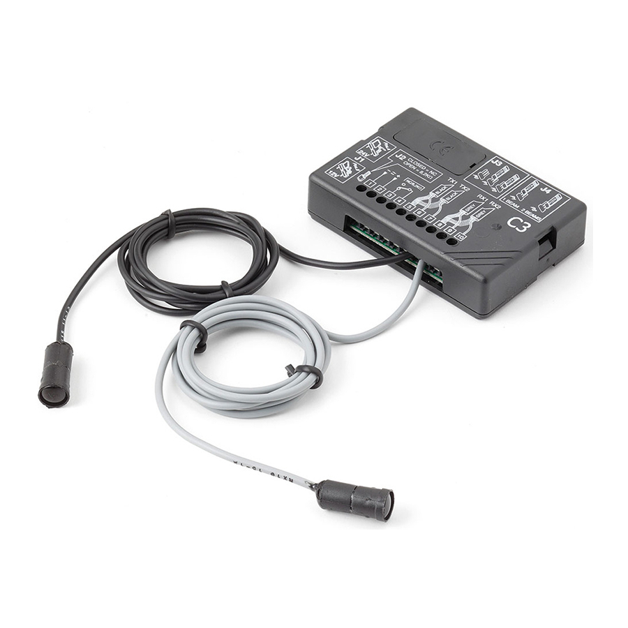
La barriera all'infrarosso modulato "CDR892C3" è composta da:
1) Una centralina di controllo CDR892C3
2) Due ottiche TX con cavi schermati NERO e supporto per fissaggio a pannello.
3) Due ottiche RX con cavi schermati GRIGIO e supporto per fissaggio a pannello.
La lunghezza dei cavi delle ottiche è diversa a seconda delle versioni:
Versione
Lunghezza cavo TX (Nero)
CDR892C3 standard
CDR892C3-1 (a richiesta)
CDR892C3-2 (a richiesta)
INSTALLAZIONE (fig.1-4)
La barriera a raggio infrarosso modulato "CDR892C3" rappresenta un efficiente sistema di sicurezza per la pro-
tezione di passaggi o spazi soggetti ad installazioni automatizzate di ascensori, porte o dove si debba rilevare il
passaggio o conteggio di persone o cose. Il sistema è adatto per l'applicazione su passaggi di luce compresi fra
1 e 15 metri all'interno e fra 1 e 10 metri all'esterno di edifici. L'uso e l'installazione di questa apparecchiatura
deve rispettare rigorosamente le indicazioni fornite dal costruttore e le normative di sicurezza vigenti.
Attenzione! Se si installano più CDR892C3 è opportuno, al fine di un corretto funzionamento, che i coni di
emissione delle singole ottiche non si sovrappongano. I due raggi devono essere distanti circa 1,5 metri
uno dall'altro nel caso di installazioni con passaggio luce compresi tra 1 e 5 metri all'interno; 2,5 metri
nel caso di installazioni con passaggio luce compresi tra 5 e 15 metri. Se vengono utilizzati due raggi il
jumper "J4" deve essere inserito nella posizione "P2", mentre se viene utilizzato un solo raggio il jumper
deve essere inserito nella posizione "P1" e le ottiche devono essere collegate ai terminali TX1 e RX1.
• Dopo aver cambiato l'impostazione del numero di raggi è necessario spegnere e riaccendere il dispositivo.
1) Determinare il passaggio luce e scegliere le ottiche adatte all'installazione. Le ottiche vengono fornite complete
di cavi che non è possibile allungare. Se invece si desidera accorciarli è preferibile intervenire sul cavo RX
cosicchè l'ottica RX risulti più vicina alla logica di controllo ricevendo così un segnale più pulito.
N.B.: evitare di spellare il cavo schermato per più di 2cm nella connessione alla morsettiera di controllo
(questo accorgimento diminuisce la sensibilità ai disturbi esterni).
2) Verificare attentamente che le superfici sulle quali si devono fissare i supporti in plastica (fig. 3a) siano in bolla
e perfettamente affacciate fra loro in quanto non è consentita una regolazione esterna.
3) Determinare il punto in cui andrà collocata la logica di controllo tenendo conto della lunghezza delle ottiche
a disposizione; se l'installazione avviene all'esterno dell'edificio la logica di controllo deve essere inserita in
contenitore stagno (IP55).
4) Prevedere il passaggio dei cavi di collegamento dalla logica di controllo al punto di fissaggio delle ottiche
(fig. 3b) evitando il collocamento in canalette in cui vi siano cavi ad alta tensione.
5) Calcolare le altezze ("H" fig.2) rispetto al suolo e marcare i punti di fissaggio dei supporti in plastica. La di-
stanza ("D" fig. 1) non influisce sul funzionamento del dispositivo. (Il multiplexing dei 2 raggi evita il problema
della sovrapposizione dei segnali). Come indicato in figura 2 i trasmettitori vanno installati sullo stesso lato;
i ricevitori vanno installati sul lato opposto.
6) Utilizzando un trapano con punta da Ø12 effettuare i fori sui punti marcati (fig. 3).
7) Inserire i supporti in plastica (fig. 3a)
8) Fissare le ottiche al supporto infilando il cavo ed esercitando una pressione (fig. 3b). Una volta bloccate, le
ottiche non possono essere estratte dall'esterno (garanzia contro la manomissione).
9) Qualora sia necessario sostituire l'ottica, scollegare il cavo di collegamento ed esercitare una pressione
dall'interno verso l'esterno per liberare l'ottica dal suo supporto in plastica.
10) Effettuare i collegamenti rispettando rigorosamente lo schema riportato in fig. 4. La sezione minima del cavo
di alimentazione deve essere di 0,2 mm
2
(AWG#24).
11) Selezionare la tipologia del contatto in uscita: NC/8.2 kΩ
12) Selezionare la portata come indicato nella tabella a pagina 4 ricordando che i dati relativi alla portata si
riferiscono ad una installazione ottimale che rispetta tutti i punti del paragrafo "Installazione".
Anomalie di funzionamento
• Il led verde d'alimentazione è spento:
- verificare il collegamento elettrico
- verificare il valore e la polarità della tensione di alimentazione (12-24 Vac/dc)
• Il led rosso d'allarme rimane sempre acceso:
- le ottiche non sono allineate;
- le ottiche sono guaste; in questo caso bisogna innanzitutto identificare la coppia TX-RX non funzionante:
inserire il jumper "J4" in posizione "P1", spegnere e riaccendere il dispositivo, se il led rosso rimane acceso
la coppia non funzionante è TX1-RX1; se il led rosso si spegne significa che la coppia non funzionante è
TX2-RX2. Quindi identificata la coppia procedere come segue:
- verificare che il raggio non sia ostacolato;
- verificare l'integrità delle ottiche;
- verificare l'integrità dei cavi.
+39/0438.404011
+39/0438.401831
Sales.office.it@cardin.it
Sales.office@cardin.it
www.cardin.it
Lunghezza cavo RX (grigio)
5 m
3 m
10 m
7 m
15 m
10 m
SERIAL NUMBER
ZVL235.03
This product has been tried and tested in the manufacturer's laboratory, du-
ring the installation of the product follow the supplied indications carefully.
ENGLISH
MODULATED INFRARED BARRIER "MINI" CDR892C3
These instructions are aimed at professionally qualified "installers of electrical equipment" and must respect the
local standards and regulations in force. Before commencing with the installation of this appliance familiarise
yourself with the safety devices required by the system, only then will you be able to use them to great effect.
This class 3 equipment has a double relay with serial exchange. The NC contact conforms to category 3 of
the directive UNI EN ISO 13849-1 (update of the EN954-1).
Attention! Only for EU customers - WEEE marking.
This symbol indicates that once the products life-span has expired it must be disposed
of separately from other rubbish.
The user is therefore obliged to either take the product to a suitable differential collection
site for electronic and electrical goods or to send it back to the manufacturer if the inten-
tion is to replace it with a new equivalent version of the same product.
Suitable differential collection, environmental friendly treatment and disposal contributes to avoiding
negative effects on the ambient and consequently health as well as favouring the recycling of materials.
Illicitly disposing of this product by the owner is punishable by law and will be dealt with according to
the laws and standards of the individual member nation.
The modulated infrared barrier "CDR892C3" is composed of:
1) A CDR892C3 control box
2) Two transmitter sensors with "BLACK" shielded cables and wall mounting support.
3) Two transmitter sensors with "GREY" shielded cables and wall mounting support.
The length of the cables differs according to the version:
Version
Cable length TX (Black)
CDR892C3 standard
CDR892C3-1 (on request)
CDR892C3-2 (on request)
INSTALLATION INSTRUCTIONS (fig. 1-4)
The modulated infrared barrier "CDR892C3" constitutes an efficient control and safety system for the protec-
tion of automatic installations such as lifts and automatic doors or and is suitable for controlling passageways
of from 1 to 15 meters inside buildings and from 1 to 10 meters outside buildings depending on the sensitivity
setting. The use and installation of these appliances must rigorously respect the indications supplied by the
manufacturer and the safety standards and regulations in force.
Caution! If you install more than one CDR892C3, in order to guarantee the correct operation, the emis-
sion cones of the individual sensors should not overlap. The two beams must be separated by at least
1,5 meters when installed in a site which has a passing room of from 1 to 5 meters; and by 2 meters
when installed in a site which has a passing room of from 5 to 10 meters). If two beams are used the
jumper "J4" must be inserted in position "P2", while if only one beam is used the jumper must be inserted
in position "P1" and the sensors will then have to be connected to the binding posts TX1 and RX1.
• After having changed the number of beams you must switch the device off and then back on again.
1) Work out the passage width and choose the sensors most suitable to your installation, remember that the
sensors come complete with cables and though it is not possible to extend them you may shorten them
(in this case it's preferable to shorten the receiver cable so as to allow it to be nearer the control box).
Warning: Do not peel the cables back by more than 2cm when wiring up to the control box as this will
reduce the device's level of resistance to external interference.
2) Make sure that the surfaces to which the sensor supports (fig. 3a) are to be fitted are not inclined and that
they are perfectly aligned as once installed the sensors cannot be adjusted externally.
3) Work out the point at which the control box is to be fitted by taking into account the length of the ca-
bles. If the control box is to be installed outdoors it must be protected by a waterproof container (IP55).
4) Run the cables from the control box to the sensors (fig. 3b) making sure that they are not passed through
ducts containing high tension wires.
5) Work out the height ("H" fig. 2) and mark the points at which the plastic supports are to be fitted. The
distance ("D" fig. 1) has no influence and does not affect the correct functioning of the appliance. (Multi-
plexing the 2 beams avoids signal overlapping problems). As shown in figure 2 the transmitters should be
installed on the same side with the receivers installed on the opposite side.
6) Drill a Ø12 hole at each installation point (fig. 3).
7) Insert the plastic supports (fig. 3a)
8) Fix the sensors to the supports by first inserting the cable and then pressing down on the sensor until it
snaps into position (fig. 3b). Once they have been fastened down the sensors cannot be extracted externally
(these are anti-tampering devices).
9) If you have replace the sensor; first disconnect the cable from the socket and then press from the inside
towards the outside to free the sensor from its plastic support.
10) Carry out the electrical connection exactly following the attached wiring diagram (fig. 4). The minimum
cable cross section area for the power cable is 0,2 mm
11) Select the type of output contact: NC/8.2 kΩ
12) Select the range as indicated in the table on page 4 remembering that the range values are strictly depend-
ent on a well executed installation which respects all the points specified in the paragraph "Installation".
Operational anomalies
• The green power led is off
- Check the electrical connection
- Check the power supply rating and polarity (12-24 Vac/dc)
• The red led alarm remains constantly lit
- The sensors are not correctly aligned
- the sensors are damaged; in this case first of all identify which pair of beams is not functioning correctly
by inserting the jumper "J4" in to position "P1", then switching the device off and back on again. If the
red led remains lit the faulty pair of beams is TX1-RX1; if the red led goes out the faulty pair of beams is
TX2-RX2. At this point proceed as follows:
- make sure that the beam is not interrupted;
- check the integrity of the sensors;
- check the integrity of the cables.
SERIES
MODEL
CDR
892C3
17-02-2003
Cable length RX (Grey)
5 m
3 m
10 m
7 m
15 m
10 m
(AWG #24).
2
DATE
Werbung

Verwandte Anleitungen für Cardin Elettronica CDR serie


Inhaltszusammenfassung für Cardin Elettronica CDR serie
- Seite 1 CARDIN ELETTRONICA spa SERIAL NUMBER SERIES MODEL DATE ZVL235.03 892C3 17-02-2003 Via del lavoro, 73 – Z.I. Cimavilla 31013 Codognè (TV) Italy Tel: +39/0438.404011 Fax: +39/0438.401831 This product has been tried and tested in the manufacturer's laboratory, du- email (Italy): Sales.office.it@cardin.it...
- Seite 2 DEUTSCH FRANÇAIS DEUTSCH BARRIERE A INFRAROUGE MODULE "MINI CDR892C3" MODULIERTE INFRAROTLICHTSCHRANKE "MINI CDR892C3" Hinweis: Das vorliegende Handbuch wendet sich an Personen, die zur Installation von "ELEKTROGERÄ- Remarque: Ce livret est destiné à des personnes titulaires d’un certificat d’aptitude professionnelle pour TEN"...
- Seite 3 PERSONA O OGGETTO CHE por el fabricante y las normas de seguridad vigentes. CARDIN ELETTRONICA S.p.A - 31020 San Vendemiano (TV) Italy - via Raffaello, 36 Tel: 0438/401818 Fax: 0438/401831 DEVE ESSERE RILEVATO. Cuidado! Si se instalan varios aparatos CDR892C3 es oportuno, a fin de obtener su funcionamiento correcto, que los conos de emisión de los dispositivos ópticos sencillos no se superpongan.
- Seite 4 Draft : P.J.Heath 23-03-2011 Zeichenerklärung RELAY CARDIN ELETTRONICA S.p.A - 31020 San Vendemiano (TV) Italy - via Raffaello, 36 Tel: 0438/401818 Fax: 0438/401831 J1 Jumper Umschaltung 12-24 V J2 Jumper auswahl NC/8.2 kΩ CLOSED = NC RELAY J3 Jumper auswahl der Reichweite OPEN = 8,2KΩ...