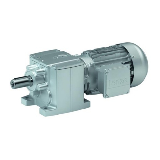
Lenze g500 Montageanleitung
Komponententausch mit zentralgewinde motor und getriebe
Vorschau ausblenden
Andere Handbücher für g500:
- Montageanleitung (128 Seiten) ,
- Montageanleitung (73 Seiten) ,
- Montageanleitung (71 Seiten)
Inhaltszusammenfassung für Lenze g500
- Seite 1 Komponententausch mit Zentralgewinde Montageanleitung Motor und Getriebe Component replacement with central thread Mounting Instructions Motor and gearbox...
- Seite 2 Stop! Diese Dokumentation ist nur gültig mit der Montageanleitung zum jeweiligen Getriebe! Hinweis! Alle Gewährleistungsansprüche erlischen bei der Ausführung dieser Arbeiten! Tipp! Informationen und Hilfsmittel rund um die Lenze−Produkte finden Sie im Download−Bereich unter www.lenze.com 0Abb. 0Tab. 0 Lenze MA 12.0022 2.0...
-
Seite 3: Inhaltsverzeichnis
Kontrolle des Nockenabstandes ....... . . Lenze ¯ MA 12.0022 ¯ 2.0... -
Seite 4: Über Diese Dokumentation
Verletzungen zur Folge haben kann, wenn nicht die entsprechenden Maßnahmen getroffen werden. Gefahr von Sachschäden Hinweis auf eine mögliche Gefahr, die Sachschäden zur Stop! Folge haben kann, wenn nicht die entsprechenden Maßnah- men getroffen werden. Lenze ¯ MA 12.0022 ¯ 2.0... - Seite 5 Über diese Dokumentation Verwendete Hinweise Anwendungshinweise Piktogramm und Signalwort Bedeutung Hinweis! Wichtiger Hinweis für die störungsfreie Funktion Tipp! Nützlicher Tipp für die einfache Handhabung Verweis auf andere Dokumentation Lenze ¯ MA 12.0022 ¯ 2.0...
-
Seite 6: Sicherheitshinweise
Dies ist Voraussetzung für einen sicheren und störungsfreien Betrieb sowie für das Erreichen der angegebenen Produkteigenschaften. ¯ Alle Arbeiten mit und an Lenze−Antriebs− und Automatisierungskomponenten darf nur qualifiziertes Fachpersonal ausführen. Nach IEC 60364 bzw. CENELEC HD 384 sind dies Personen, ... -
Seite 7: Produktbeschreibung
Motor Sicherungsnocken Sicherungsschraube Die g500 Getriebe−Baureihe verfügt als antriebsseitige Motorschnittstelle über ein 4−gängiges Zentralgewinde. Bei dem Gewinde handelt es sich um ein normales Rechts- gewinde, d. h. Festziehen im Uhrzeigersinn, Lösen gegen den Uhrzeigersinn. Das Ge- winde wird mittels einer Sicherungslasche und einer tangentialen Schraube angezogen und gesichert. -
Seite 8: Mechanische Installation
4.2.2 Demontage Für Ausführungen bei denen eine abgewinkelte Sicherungslasche vorhanden ist (¶ 7), ist eine spezielle Demontagelasche notwendig, welche über den Lenze Service zu bezie- hen ist. Nachfolgende Schritte zur Demontage unterscheiden sich individuell durch die unter- schiedlichen Massen von Motor und Getriebe. Grundsätzlich sollte die leichtere Kompo- nente gedreht und die schwerere Komponente fixiert werden. -
Seite 9: Demontieren Der Sicherungslasche
2. Die Sicherungsschraube anziehen bis die Sicherungsnocken von Getriebegehäuse und Motor bündig an der Sicherungslasche anliegt, Abb. 5. Anzugsdrehmomente der Schrauben (¶ 13). Abb. 4 Montage gegenüberliegende Seite (Beginn des Einschraubens) Sicherungsschraube Sicherungsnocke Sicherungslasche Lenze ¯ MA 12.0022 ¯ 2.0... - Seite 10 Wegverlängerung durch Zwischen− Lösen legen eines Distanzstückes 4. Motor bzw. Getriebe ca. 1.5 Umdrehungen gegen den Uhrzeigersinn zurückdrehen und dadurch den Motor vom Getriebe bzw. das Getriebe vom Motor trennen (ausheben). 5. Sicherungslasche und Sicherungsschraube demontieren. Lenze ¯ MA 12.0022 ¯ 2.0...
-
Seite 11: Montage Der Neuen Komponente
B Gewinde, den Bereich von O−Ring und Zentrierung (Abb. 7 und Abb. 8) auf mögliche Fress−Spuren untersuchen. Ggf. vorstehendes Material oder Fress−Spuren sind vorsichtig zu entfernen, z. B. mit einer kleinen Feile. Hinweis! Bei der Nacharbeit Motor und Getriebe unbedingt vor Verunreinigungen schützen! Lenze ¯ MA 12.0022 ¯ 2.0... -
Seite 12: Montage
Punkt 3 "Antrieb verdrehsicher fixieren"). 1. Am Motor sind die Bereiche Zentrierung, O−Ring und Gewinde mit der mitgelieferten Montagepaste (Lenze Ident−Nr. 13211352) oder alternativ Rivolta G.W.F dünn zu bestreichen, da sonst Gefahr des Fressens besteht. 2. Neuen O−Ring mit Montagepaste bestreichen und auf den Zentrierbereich des Außengewindes (Motor) montieren. -
Seite 13: Kontrolle Des Nockenabstandes
Nockenabstand und Anzugsdrehmomente der Sicherungsschraube Stop! Ist der Nockenabstand "a" gemäß Tabellenwert zu klein, dürfen die Bauteile nicht zusammen verbaut werden. Rücksprache mit Lenze erforderlich! Bei zu geringem Nockenabstand wird durch das Anziehen in dem Zentralgewinde keine ausreichende Vorspannung erreicht. Die Teile sind dann nicht fest verbunden! Lenze ¯... - Seite 14 Nach dem Anziehen der Sicherungsschraube ist die Endstellung des Zentralgewindes zu kontrollieren. Abb. 11 Endstellungskontrolle Zentralgewinde Nockenabstand "a" < 1.5 mm Die Nocken sollen möglichst bündig sein bzw. um nicht mehr als 1.5 mm gegeneinander versetzt stehen (Abb. 11). Lenze ¯ MA 12.0022 ¯ 2.0...
- Seite 15 Abschließend kontrollieren, dass weder die Sicherungsschraube noch die Sicherungs− lasche verbogen/beschädigt ist. Verbogene/beschädigte Teile müssen ersetzt werden. Neues Öl auffüllen (, Montageanleitung g500). Die Ölmenge ist entsprechend der Einbaulage im Betrieb zu wählen. Es wird empfohlen anschließend den korrekten Öl- stand zu kontrollieren.
- Seite 16 Notizen Lenze ¯ MA 12.0022 ¯ 2.0...
- Seite 31 Notes Lenze ¯ MA 12.0022 ¯ 2.0...
- Seite 32 © 05/2017 | MA 12.0022 | .SXõ | 2.0 | TD09 Lenze Drives GmbH Postfach 10 13 52, 31763 Hameln Breslauer Straße 3, 32699 Extertal GERMANY HR Lemgo B 6478 Ü +49 5154 82−0 Ø +49 5154 82−2800 Ù lenze@lenze.com Ú...


