TCS 3000 Installationsanleitung

Inhaltszusammenfassung für TCS 3000
- Seite 1 TCS 3000 Installation TCS 3000 Catalog Title ELECTRONIC REGISTER ELEKTRONISCHES REGISTER Catalog Subtitle Installation Manual Installationsanleitung Total Control Systems www.tcsmeters.com...
-
Seite 2: Inhaltsverzeichnis
TCS 3000 Installation TCS 3000 Installation Installation des Funkmodems Inhaltsverzeichnis Table of Contents Installation des Sierra-Mobilfunkmodems IInhaltsverzeichnis Installation des Maestro-Mobilfunkmodems Erhalt und Überprüfung Installation der Fernanzeige Table of Contents Radio Modem Installation Installation der 1-Kanal-Kommunikationsplatine Hinweis Sierra Cellular Modem Installation Receipt & Inspection Einleitung 1-Kanal-Dichteinstallation Maestro Cellular Modem Installation Notice... -
Seite 3: Receipt & Inspection
Total Control Systems (TCS) shall not be liable for technical or editorial errors in this manual or omissions from this manual. TCS makes no warranties, express or implied, including the implied warranties of merchantability and fitness for a particular purpose with respect to this manual and, in no event, shall TCS be liable for special or consequential Total Control Systems (TCS) haftet nicht für technische oder redaktionelle Fehler in diesem Handbuch oder damages including, but not limited to, loss of production, loss of profits, etc. -
Seite 4: Introduction
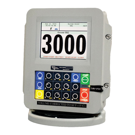
The Open Software Architecture provides the option of a simple “Pump & Print” delivery or a custom measure- steuert. Die Open Software Architecture bietet die Option einer einfachen „Pump & Print“ -Lieferung oder einer ment solution. The TCS 3000 features a 4.5”x 3.5” full color VGA display screen, multiple delivery screens and a backlit benutzerdefinierten Messlösung. Der TCS 3000 verfügt über ein 4,5 “x 3,5” großes Farb-VGA-Display, mehrere Lieferbildschirme und ein beleuchtetes alphanumerisches Tastenfeld für die Benutzeroberfläche. Erhältlich in flexiblen Montagekonfigurationen mit... -
Seite 5: Abmessungen System Specifications
TCS 3000 Installation TCS 3000 Installation Die USB0- und USB1-Anschlüsse dienen nur zur Wartung. Um auf diese Anschlüsse zugreifen zu können, The USB0 and USB1 ports are for maintenance only. To access these connectors, power to the unit must be disconnected and the area known to be free of ignitable gas or equivalent. muss die Stromversorgung des Geräts unterbrochen werden und der Bereich muss frei von zündfähigem Gas oder Ähnlichem sein. -
Seite 6: Installationsverfahren - Messgerät Der Serie Tcs 682
3. Schieben Sie die Antriebskupplung auf die Antriebswelle des Messgeräts. 4. Drehen Sie das TCS 3000-Register, bis die Anzeige in die gewünschte Richtung zeigt, und prüfen Sie, ob 4. Rotate the TCS 3000 register until the display is facing in the desired direction and check to see that the meter die Löcher des Messgeräts mit den Löchern an der Basis des TCS 3000-Registers übereinstimmen. holes align with the holes at the base of the TCS 3000 register. -
Seite 7: Installationsverfahren - Messgerät Der Serie Tcs 700
4. Slide the Drive Coupling onto the Meter Drive Shaft. 4. Schieben Sie die Antriebskupplung auf die Antriebswelle des Messgeräts. 5. Rotate the TCS 3000 register until the display is facing in the desired direction and check to see that the meter 5. Drehen Sie das TCS 3000-Register, bis die Anzeige in die gewünschte Richtung zeigt, und prüfen Sie, ob holes align with the holes at the base of the TCS 3000 register. -
Seite 8: Installationsverfahren - 3000 Fernmontage
Packen Sie vor Beginn der Installation des TCS 3000-Registers den gesamten Verpackungsinhalt an einem sicheren Ort aus, an dem Sie keine Teile verlegen können. Die Teile so auslegen, wie sie eingebaut werden Before beginning the installation of the TCS 3000 register, unpack the entire contents of the packaging in a safe loca- würden. Dadurch wird sichergestellt, dass Sie alle richtigen Teile für die Installation haben. Wenn Sie im tion where you will not misplace any of the parts. Lay out the parts as they would be installed. This will ensure that Voraus überprüfen, ob alle erforderlichen Teile im Lieferumfang enthalten sind, können Sie Ausfallzeiten... -
Seite 9: Abmessungen Für Tcs 3000 Remote
TCS 3000 Installation TCS 3000 Installation TCS 3000 Remote Dimensions Abmessungen für TCS 3000 Remote 5/16-24 MOUNTING HOLES BEFESTIGUNGSBOHRUNGEN Total Control Systems www.tcsmeters.com... -
Seite 10: Installation Des Coriolis-Messgeräts Remote Meter Mounting Dimensions
2. Setzen Sie das Register auf die Halterung und drehen Sie das Register TCS 3000, bis das Display in die gewünschte 2. Place the register on the mounting bracket and rotate the TCS 3000 register until the display is facing in the desired Richtung zeigt. Vergewissern Sie sich, dass die Bohrungen des Messgeräts mit den Bohrungen an der Basis des TCS direction. Check to see that the meter holes align with the holes at the base of the TCS 3000 register. -
Seite 11: Installation Des Erdungsbands Coriolis Meter Installation
Installation Procedure — Grounding Strap # 8 Erdungsband #8 Grounding Strap Kabelbinder 1/4” Schrauben Zip Ties und Muttern 1/4” Hardware TCS 300597, Grounding Strap Kit TCS 300597, ERDUNGSRIEMENSATZ Installationsverfahren Installation Procedure: GRUNDIERUNG EINES LKW-SITZES: GROUNDING A TRUCK SEAT: Befestigen Sie das Mount ground strap using sup- Erdungsband mit den... -
Seite 12: Installation Des Einschaltzeitrelais Grounding Strap Installation
Power On Timing Relay Bei der Installation des TCS 3000-Registers an Lieferwagen wird empfohlen, ein Zeitrelais für den When installing the TCS 3000 register on delivery tank trucks, it is recommended to use a timing relay for safe startup of the TCS sicheren Start des TCS 3000-Registers zu verwenden. Installieren Sie das Einschaltzeitrelais TCS 300289 3000 registration. Install the TCS 300289 Power On Time Relay from the Accessory Ignition (ACC) to the TCS 3000 register for a von der Zubehörzündung (ACC) zum TCS 3000-Register für eine wählbare Zeit (Sekunden), in der die... -
Seite 13: Direktmontage Des Pulsers Power On Time Relay Installation
TCS 3000 Installation TCS 3000 Installation Installation Procedure — Direct Mount Pulser Installationsverfahren - Direktmontage des Pulsers www.tcsmeters.com Total Control Systems... -
Seite 14: Test Pulser Installation Direct Mount Pulser Installation
Installation Procedure — Test Pulser Vor der Inbetriebnahme des Liquid-Handling-Systems kann der Distributor mithilfe des TCS 3000-Registers Prior to putting the liquid handling system into service, the distributor can utilize the TCS 3000 register TEST PULSER to verify that TEST PULSER prüfen, ob alle Ein- / Ausgänge ordnungsgemäß funktionieren. Der Test Pulser simuliert eine all Inputs/Outputs are working correctly. The Test Pulser will simulate an actual product delivery without having to pump product tatsächliche Produktabgabe, ohne dass das Produkt durch das Messgerät gepumpt werden muss. Verwenden... -
Seite 15: Installation Von Pumpe Und Drehzahl / Gas Test Pulser Installation
1. Locate the Pump Control (PMP. CTRL) position on the terminal 1. Suchen Sie die Position der Pumpensteuerung (PMP. CTRL) auf der board. Klemmenleiste. 2. Screw the cable gland into the back of the TCS 3000 register and 2. Schrauben Sie die Kabelverschraubung in die Rückseite des TCS tighten into the housing. 3000-Registers und ziehen Sie sie am Gehäuse fest. 3. Run the Pump Control to the onboard computer or programma- 3. Führen Sie die Pumpensteuerung über die Kabelverschraubung zum... -
Seite 16: Einbau Der Externen Und Kolbenadditiven Einspritzpumpe Pump & Speed/Throttle Control Installation
TCS 3000 Installation TCS 3000 Installation Installationsverfahren - Additive Einspritzpumpe Installation Procedure — Additive Injection Pump Es gibt zwei Möglichkeiten, um additive Einspritzpumpen zu verwalten. Außen- und Kolben. There are two selections for managing Additive Injection Pumps; External and Piston. EXTERN: Die externe Funktion für die additive Einspritzung dient dazu, während des gesamten Lieferprozesses EXTERNAL: The External function for Additive Injection is to... -
Seite 17: Installation Der Additiv-Einspritzpumpe External & Piston Additive Injection Pump Installation
TCS 3000 Installation TCS 3000 Installation Installation Procedure — Additive Injection Pump Installationsverfahren - Additive Einspritzpumpe DRUCK: DIE DRUCKFUNKTION FÜR DIE ADDITIVE PRESSURE: The Pressure function for Additive Injection is to pro- EINSPRITZUNG DIENT DAZU, WÄHREND DES GESAMTEN vide a positive output signal during the entire delivery process to FÖRDERPROZESSES EIN POSITIVES AUSGANGSSIGNAL ZU LIEFERN, UM EINE EXTERNE ADDITIVE EINSPRITZPUMPE drive an external additive injection pump. - Seite 18 1. Die Verdrahtung des Luftentfernungsschwimmers am 1. Locate the air eliminator float wiring on the metering system. Dosiersystem lokalisieren. 2. Installieren Sie die Kabelverschraubung auf der Rückseite des 2. Install the cable gland into the back of the TCS 3000 register TCS 3000-Registers und ziehen Sie sie am Gehäuse fest. and tighten into the housing. 3. Führen Sie die Schwimmerkabel des Luftabscheiders durch 3. Run the air eliminator float wiring through the cable gland.
-
Seite 19: Installationsverfahren - Vibronic Eletronisch Luft Eliminator
1. Connect Independent +24VDC to Terminal Block L1 in the Vibronic Sensor 1. Verbinden Sie Independent + 24VDC mit Klemmenblock L1 im Vibronic Sensor 2. Connect Terminal Block 7 to “GND” and Terminal Block 8 to “Air Elim.” under Air Eliminator Section of the TCS 3000 register. 2. Schließen Sie den Klemmenblock 7 an „GND“ und den Klemmenblock 8 an „Air Elim“ im Abschnitt „Air Eliminator“ des TCS 3000-Registers... - Seite 20 4. Once the solenoid is wired, run the corresponding wire as pictured using a minimum of 18 gauge shielded cable 4. Wenn der Elektromagnet verdrahtet ist, führen Sie den entsprechenden Draht wie abgebildet mit einem into the back of the TCS 3000 register. The 3 Way valve will be wired into Solenoid 2 on the terminal board. abgeschirmten Kabel von mindestens 18 Gauge in die Rückseite des TCS 3000-Registers. Das 3-Wege- 5.
- Seite 21 4. Once the solenoid is wired, run the corresponding wire as pictured using a minimum of 18 gauge shielded cable 4. Wenn der Elektromagnet verdrahtet ist, führen Sie den entsprechenden Draht wie abgebildet mit einem into the back of the TCS 3000 register. The 3-Way Valve will be wired into Solenoid 1 (S1) on the terminal board abgeschirmten Kabel von mindestens 18 Gauge in die Rückseite des TCS 3000-Registers. Das 3-Wege- Ventil wird an Magnet 1 (S1) auf der Klemmenleiste und das Bypass-Ventil für langsamen Durchfluss an...
- Seite 22 3. Wenn der Elektromagnet verdrahtet ist, führen Sie tured using a minimum of 18 gauge shielded cable into the back den entsprechenden Draht wie abgebildet mit einem of the TCS 3000 register. abgeschirmten Kabel von mindestens 18 Gauge in die Rückseite des TCS 3000-Registers. 4. Insert the solenoid wiring into the cable gland. Wire the solenoid 4. Führen Sie die Magnetkabel in die Kabelverschraubung...
-
Seite 23: Installationsverfahren - 2-Stufen-Voreinstellventil
18 gauge shielded cable into the back 3. Verlegen Sie nach dem Verdrahten der Magnetspulen of the TCS 3000 register. den entsprechenden Draht wie abgebildet mit einem abgeschirmten Kabel von mindestens 18 Gauge in die 4. Insert the solenoid wiring into the cable gland. Wire the solenoid Rückseite des TCS 3000-Registers. -
Seite 24: Temperature Probe Installation
7. Compress the cable gland on the TCS3000 register until it is snug on the temperature probe wire. Temperaturfühlers anliegt. 8. Führen Sie die Verdrahtung des Temperaturfühlers zur Rückseite des TCS 3000-Registers. Führen Sie die 8. Run the temperature probe wiring to the back of the TCS 3000 register. Insert the wiring into the third cable gland Verdrahtung wie in der Abbildung oben in die dritte Kabelverschraubung von oben in das Register ein. from the top of the register as in the illustration above. -
Seite 25: Temperature Probe Installation Kits
TCS 3000 Installation TCS 3000 Installation Installation Procedure — Temperature Probe Kit Installationsverfahren - Temperatursonden-Kit TCS 3000 RTD Sonde/Aluminium Schutzrohrsatz TCS 3000 RTD Probe/Aluminum Thermowell Kit Item TCS 300811 Beschreibung Menge TCS 300811 Cable Gland, 1/2 NPT UL TCS 300133 Kabelverschraubung, 1/2 NPT UL O-Ring, 1/2 NPT Gland TCS 300255 O-Ring, 1/2 NPT Drüse... -
Seite 26: Daisy Chain Kommunikation
TCS 3000 Installation TCS 3000 Installation Installation Procedure — Daisy Chain Communication Installationsverfahren — Digitale Kommunikationskette Digitale Kommunikationskette: zum Austausch von Informationen und Zubehör Daisy Chain: Daisy Chain wird zum Verknüpfen mehrerer Register verwendet, um einen Drucker oder ein Modem zum Daisy Chain is used for linking multiple registers together to use one printer or modem to link multiple registers to the Verknüpfen mehrerer Register mit der Datenbank zu verwenden. -
Seite 27: Druckerinstallation Printer Installation
TCS 3000 Installation TCS 3000 Installation Installation Procedure — Printer Installationsverfahren - Drucker WEISS BLAU SCHWARZ PIN 3: TX - GETRIEBE PIN 2: RX PIN 7: ELEKTRISCHER BODEN REZEPTION Installation Procedure: Installationsverfahren: 1. Find a suitable location for the printer appropriate to your application. 1. Suchen Sie einen geeigneten Standort für den Drucker, der zu Ihrer Anwendung passt. 2. Secure the printer in place with the Velcro strip provided. -
Seite 28: Druckerinstallationskits Printer Installation Kits
Epson Loseblattdrucker Epson Printer TEL TMU295-011 TEL TMU295-011 Wehof Bestellformular Wehof Order Form TCS WEHOF TCS WEHOF TCS 3000 Epson Loseblattdrucker 24 VDC Kit TCS 3000 Epson Slip 24 VDC Print Kit Artikel Menge TCS 300885 TCS 300985 Item TCS 300885 TCS 300985 Metrischer... -
Seite 29: Druckerinstallationskits (Fortsetzung) Printer Installation Kits (Continued)
Epson Rollendrucker Roll Printer TEL TMU220A103 TEL TMU220A103 Wehof Bestellformular Wehof Order Form TCS WEHOF TCS WEHOF TCS 3000 Epson Rollendrucker 24 VDC Kit TCS 3000 Epson Roll 24 VDC Print Kit Artikel Menge TCS 300884 TCS 300984 Item TCS 300884 TCS 300984 Metrischer... -
Seite 30: Druckerinstallationskits (Fortsetzung) Printer Installation Kits (Continued)
TCS 300723 DC LKW/Adapter/Citizen DC Truck Adapter/Citize TCS 300724 TCS 300724 Wehof Bestellformular Wehof Order Form TCS WEHOF TCS WEHOF *Bluetooth Modem will not pair with other devices, unless TCS Programs the device at the Factory* *Bluetooth-Modem kann nicht mit anderen Geräten gekoppelt werden, es sei denn, TCS programmiert das Gerät ab Werk. * www.tcsmeters.com Total Control Systems... -
Seite 31: Installationsverfahren - Zeitverzögerungsrelais Ausschalten
Bei der Installation der TCS 3000-Registrierung in Lieferwagen mit Mobilfunkmodems wird empfohlen, ein Zeitrelais für das Ausschalten des Modems vorzusehen und sich zu registrieren, um alle Lieferaufzeichnungen When installing the TCS 3000 registration on delivery tank trucks with Cellular Modems, it is recommended to provide a timing re- vollständig zu übertragen. Installieren Sie das Ausschaltzeitrelais vom Zubehörschalter (ACC) zum TCS lay for the power off of the modem and register to completely transmit all delivery records. Install the Power Off Time Relay from 3000-Register für eine wählbare Zeit (Sekunden), in der die Stromversorgung unterbrochen ist. -
Seite 32: Installation Des Funkmodems
SCHWARZ 1. Verbinden Sie das 9DB-Pin-Kommunikationskabel mit dem of the TCS 3000 register terminal board. Computeranschluss (COMP.) Der TCS 3000-Registerklemm- 2. Radio modems can be powered within the TCS 3000 register, via the leiste. Power Input. 2. Funkmodems können über den Stromeingang im TCS 3. Antenna must be connected to cellular modem for there to be any 3000-Register mit Strom versorgt werden. -
Seite 33: Installation Des Sierra-Mobilfunkmodems
1. Wire the 9DB Pin Communication Cable to the Computer (COMP.) port of BROWN BRAUN 1. Verbinden Sie das 9DB-Pin-Kommunikationskabel BLUE the TCS 3000 register terminal board. BLAU BLACK SCHWARZ mit dem Computeranschluss (COMP.) Der TCS 2. Cellular modems come with their own Power Cable & Plug. The Red &... -
Seite 34: Statusanzeige
BLAU BLUE BLACK SCHWARZ 1. Verbinden Sie das 15-polige DB-Kommunikationskabel the TCS 3000 register terminal board. mit dem Computeranschluss (COMP.) Der TCS 2. Cellular modems come with a Power Cable & Plug. The Green wire must 3000-Registerklemmleiste. be wired to the External Power Source (accessory switch) together. The 2. Mobilfunkmodems werden mit Stromkabel und Stecker White wire must be wired to Battery ground. - Seite 35 Installationsverfahren: Anweisungen zur RS-485-Programmierung und -Verdrahtung finden Sie in den Handbüchern der seriellen Slave- See Red Lion, Omega or Tekinno serial slave display manuals for RS-485 programming and wiring Instructions. Displays von Red Lion, Omega oder Tekinno. WARNING: The external remote display requires an External Power Source, do not pull power from the TCS 3000 WARNUNG: Für die externe Fernanzeige ist eine externe Stromquelle erforderlich. Ziehen Sie keinen Strom aus dem register. TCS 3000-Register.
-
Seite 36: Sierra Cellular Modem Installation
TCS 3000 Installation TCS 3000 Installation Installation Procedure — 1 Channel Communication Installation Installationsverfahren - Installation der 1-Kanal-Kommunikation COMMUNICATION BOARD KOMMUNIKATIONSKARTE M4 X 11 STANDOFF M4 X 14 STANDOFF M4 X 11 DISTANZBOLZEN M4 X 11 DISTANZBOLZEN SCREWS SCHRAUBEN VERDRAHTUNGSSCHILD WIRING SHIELD Installationsverfahren: Installation Procedure: 1. Entfernen Sie die sechs Schrauben, mit denen der Kabelschirm an den Abstandshaltern M8 x 27 befestigt 1. -
Seite 37: 1-Kanal-Dichteinstallation Maestro Cellular Modem Installation
TCS 3000 Installation TCS 3000 Installation Installation Procedure — Density Sensor Installationsverfahren - Dichtesensor SCHWARZ BLAU VERKABELUNGSANLEITUNGEN: 1. Installieren Sie die Einkanal-Kommunikationskarte wie auf Seite 34 beschrieben. Wiring Instructions: 2. Die rote 4-20 mA-Spannung wird an der + USUP-Klemme (geregelt auf + 18 VDC) abgeschlossen. 1) Install the single channel communication board as described on page 34. 3. Das Signalkabel ist das RX-Terminal. 2) The Red 4-20 mA power will be terminated on the +USUP terminal (regulated to +18Vdc). -
Seite 38: 1-Kanal Gtp Differenzdruck (Dp) Installation Remote Display Installation
TCS 3000 Installation TCS 3000 Installation Installation Procedure — Differential Pressure (Voltage) Installationsverfahren - Differenzdruck (Spannung) SCHWARZ BLAU GTP 7534 Differential Druckkolbenmanometer mit Drehgeber GTP 7534 Differential Pressure Piston Gauge with Rotary Encoder Verkabelungsanleitungen: Wiring Instructions: 1) Install the single channel communication board as described on page 34. -
Seite 39: 1-Kanal-Differenzdruck (Dp) -Installation 1-Channel Communication Board Installation
TCS 3000 Installation TCS 3000 Installation Installation Procedure — Differential Pressure (Current) Installationsverfahren - Differenzdruck (Strom) Analog Differential Pressure Sensor Analoger Differenzdrucksensor 1-Kanal Dwyer R X (Schwarz und Blau) - und Com +USUP (Tot) Wiring Instructions: Verkabelungsanleitungen: 1) Install the single channel communication board as described on page 34. -
Seite 40: 1-Kanal-Tankfüllstandsüberwachung 1-Channel Density Installation
TCS 3000 Installation TCS 3000 Installation Installation Procedure — 1 Tank Level Monitor Installationsverfahren - 1 Tankfüllstandsüberwachung Zu: 4-20mA Eingang TO: 4-20mA Input vom Tank Monitor from Tank Monitor Schwarz Grün Verkabelungsanleitungen: Wiring Instructions: 1. Installieren Sie die Einkanal-Kommunikationskarte wie auf Seite 34 beschrieben. 1) Install the single channel communication board as described on page 34. -
Seite 41: Wiring Instructions
5) The FAUDI eurofast® connector should be wired with the BROWN wire to +I and BLUE to –I on the IS barrier. verdrahtet werden. 6) Power the IS barrier separately from the TCS 3000 register. 6. Versorgen Sie die IS-Schranke separat vom TCS 3000-Register mit Strom. 7) Connect the eruofast® connection to the FUADI AFGUARD™ water sensor. -
Seite 42: Installation Des 1-Kanal-Parker-Velcon-Wassersensors 1-Channel Differential Pressure (Dp) Installation
TCS 3000 Installation TCS 3000 Installation Installation Procedure — Water Defense Sensor—Parker Installationsverfahren - Wasserschutzsensor - Parker Zu 4-20 mA pro Innenseite TO: 4-20mA Input vom Wassersensor from Water Sensor GND - Schwarz und 4-20mA Return (Blau) RX - 4-20 mA außen (weiß) + USUP - + VDC (Kaffee) Verdrahtungsanweisungen: Wiring Instructions: 1) Installieren Sie die Einkanal-Kommunikationskarte wie auf Seite 34 angegeben. 1) Install the single channel communication board as described on page 34. - Seite 43 TCS 3000 Installation TCS 3000 Installation Installation Procedure — 3 Channel Communication Installation Installationsverfahren - Installation der 3-Kanal-Kommunikation 3-Kanal-Karte COMMUNICATION BOARD 3 CH Trennzeichen M4 x 14 M4 X 11 STANDOFF M4 X 14 STANDOFF Trennzeichen M4 x 11 Schrauben SCREWS Kabelschirm WIRING SHIELD Installation Procedure: Verdrahtungsanweisungen: 1.
- Seite 44 TCS 3000 Installation TCS 3000 Installation Installation Procedure — 3 Channel Communication Installation Installationsverfahren - Installation der 3-Kanal-Kommunikation Wiring Instructions: Verkabelungsanleitungen: 1) Wire Power and Ground for 3 Channel Board in with the Main Power and Ground for the 1) Verdrahten Sie die Stromversorgung und Masse für die 3 - Kanal - Platine mit der TCS 3000 Stromversorgung und Masse für die TCS 3000...
- Seite 45 TCS 3000 Installation TCS 3000 Installation Installation Procedure — Density Sensor Installationsverfahren - Dichtesensor GND Schwarz =Erdungskabel - Blau VS1 (2) (3) - Rot Wiring Instructions: Verkabelungsanleitungen; 1) Install the three channel communication board as described on page 41. 1) Installieren Sie die Drei-Kanal-Kommunikationskarte wie auf Seite 41 beschrieben. 2) The Red 4-20 mA power will be terminated on the VS1(2)(3) terminal (regulated to +18Vdc).
- Seite 46 TCS 3000 Installation TCS 3000 Installation Installation Procedure — Differential Pressure (Voltage) Installationsverfahren - Differenzdruck (Spannung) - Schwarz - Blau VS1 (2) (3) - **HINWEIS** **NOTE** Bei Verwendung der Gammon-Anzeige When using the Gammon Gauge You MUST Flip Switch to 5VDC Sie müssen den Schalter auf...
-
Seite 47: 3-Channel Density Installation
TCS 3000 Installation TCS 3000 Installation Installation Procedure — Differential Pressure (Current) Installationsverfahren - Differenzdruck (Strom) 3-Kanal Dwyer - Vo und Com VS1 (2) (3) - V im Drähte in Dwyer Vo und Com sind miteinander verbunden und auf 3-Kanal-Platine mit RX verbunden... -
Seite 48: Installation Der 3-Kanal-Tankfüllstandsüberwachung 3-Channel Gtp Differential Pressure (Dp) Installation
TCS 3000 Installation TCS 3000 Installation Installation Procedure — 1 Tank Level Monitor Installationsverfahren - 1 Tankfüllstandsüberwachung Schwarz Grün VS1 (2) (3) Verkabelungsanleitungen: Wiring Instructions: 1) Installieren Sie die Drei-Kanal-Kommunikationskarte wie auf Seite 41 beschrieben. 1) Install the three channel communication board as described on page 41. 2) Die rote 4-20-mA-Spannung wird an der Klemme VS1 (2) (3) (geregelt auf +18 VDC) abgeschlossen. 2) The Red 4-20 mA power will be terminated on the VS1(2)(3) terminal (regulated to +18Vdc). -
Seite 49: Installation Des 3-Kanal-Faudi-Wassersensors 3-Channel Differential Pressure (Dp) Installation
5) The FAUDI eurofast® connector should be wired with the BROWN wire to +I and BLUE to –I on the IS barrier. 5) Der FAUDI eurofast -Stecker sollte mit dem BRAUNEN Kabel an + I und BLAU an –I an der IS-Barriere verdrahtet ® werden. 6) Power the IS barrier separately from the TCS 3000 register. 6) Schalten Sie die IS-Schranke getrennt vom TCS 3000-Register ein. 7) Connect the eruofast® connection to the FUADI AFGUARD™ water sensor. 7) Verbinden Sie den eurofast -Anschluss mit dem FUADI AFGUARD Wassersensor. -
Seite 50: Installation Des 3-Kanal-Parker-Velcon-Wassersensors 3-Channel Tank Level Monitor Installation
TCS 3000 Installation TCS 3000 Installation Installationsverfahren - Wasserschutzsensor - Parker Installation Procedure — Water Defense Sensor—Parker Bis: 4-20 mA Ausgang TO: 4-20mA Input vom Wassersensor from Water Sensor GND - GND (Schwarz) und 4-20mA Return (Blau) RX - 4-20mA Aus (Weiß) VS(1-3) - +V DC (Braun) Verkabelungsanleitungen: Wiring Instructions: 1) Install the single channel communication board as described on page 41. -
Seite 51: Installation Der 8-Kanal-Kommunikationsplatine 3-Channel Faudi Water Sensor Installation
TCS 3000 Installation TCS 3000 Installation Installation Procedure — 8 Channel Communication Installationsverfahren - 8-Kanal-Kommunikation www.tcsmeters.com Total Control Systems... -
Seite 52: 8-Kanal-Dichteinstallation 3-Channel Parker Velcon Water Sensor Installation
TCS 3000 Installation TCS 3000 Installation Installation Procedure — 8 Channel Communication—Densitometer Installationsverfahren - 8-Kanal-Kommunikation - Densitometer Schwarz Blau www.tcsmeters.com Total Control Systems... -
Seite 53: 8-Kanal Gtp Differenzdruck (Dp) Installation 8-Channel Communication Board Installation
TCS 3000 Installation TCS 3000 Installation Installation Procedure — 8 Channel Communication—DP—Gammon Installationsverfahren - 8-Kanal-Kommunikation - DP - Gammon Schwarz Blau Total Control Systems www.tcsmeters.com... - Seite 54 TCS 3000 Installation TCS 3000 Installation Installation Procedure — 8 Channel Communication—DP—Dwyer Installationsverfahren - 8-Kanal-Kommunikation - DP - Dwyer Kanäle Dwyer Vo und Com www.tcsmeters.com Total Control Systems...
- Seite 55 TCS 3000 Installation TCS 3000 Installation Installation Procedure — 8 Channel Communication—Tank Level Installationsverfahren - 8-Kanal-Kommunikation - Tankfüllstände Schwarz Grün www.tcsmeters.com Total Control Systems...
- Seite 56 TCS 3000 Installation TCS 3000 Installation Installation Procedure — 8 Channel Communication—Water - Faudi Installationsverfahren - 8-Kanal-Kommunikation - Wasser - Faudi Braun BROWN = + I Blau BLUE = - I www.tcsmeters.com Total Control Systems...
- Seite 57 TCS 3000 Installation TCS 3000 Installation Installation Procedure — 8 Channel Communication—Water - Parker Installationsverfahren - 8-Kanal-Kommunikation - Wasserparker GND (Schwarz) und 4-20 mA Rückleitung (blau) 4-20mA aus (Weiß) + VDC (Braun) www.tcsmeters.com Total Control Systems...
-
Seite 58: Installationsverfahren Für Generation 1 - Software-Aktualisierung
2. Öffnen Sie das TCS 3000-Register. Auf der Vorderseite des Registers befinden sich 2 Mini-USB- Anschlüsse. Schließen Sie den USB-Stick mit einem im Lieferumfang enthaltenen USB-Kabel an den USB- 2. Open the TCS 3000 register. On the front cover of the register, there are 2 mini-USB connections. Using a factory Anschluss an, der sich am nächsten an der Innenseite des Registers befindet. Dieser Port ist der höchste supplied USB cable, attach the thumb drive to the USB port closest to the inside of the register. This port is the auf der Platine der beiden. Siehe Abbildung 1. -
Seite 59: Installationsverfahren Für Generation 2 - Software
2. Open the TCS 3000 register. On the front cover of the register, is a USB connection. Using a factory supplied USB, attach the thumb drive to the USB port to the inside of the register. See Figure 2. -
Seite 60: Deckblattunterschiede
TCS 3000 Installation TCS 3000 Installation Generation 1 Terminal Board vs. Generation 2 Terminal Board Differences Unterschiede Zwischen der Klemmenleiste der 1. Generation und der Klemmenleiste der 2. Generation 1. Generation 1. Generation Image Image Generation 1 Image Generation 2 Image USB 3.0 in... -
Seite 61: Led Rein Und Raus
TCS 3000 Installation TCS 3000 Installation LED Rein und raus LED I/O Indicators Indikatoren Indicator Lights Advise When There is Power to the Terminal Strip Kontrollleuchten zeigen an Wenn es Strom gibt zur Klemmleiste Fähigkeit, Energie zu tanken Ability to Power... -
Seite 62: Generation 1 & 2 Austauschbarkeit
TCS 3000 Installation TCS 3000 Installation Generation 1 & 2 Interchangeability Generation 1 & 2 Austauschbarkeit Figure A Figure B Abbildung A Abbildung B INCOMPATIBLE COMPATIBLE UNVEREINBAR KOMPATIBEL Klappen Sie den Schalter nach oben, Flip switch up to use Genera-... -
Seite 63: Installationsverfahren - Vordere Abdeckung Des Ersatzregisters
TCS 3000 Installation TCS 3000 Installation Installationsverfahren - Vordere Abdeckung des Ersatzregisters Installation Procedure — Replacement Register Front Cover HINGE PIN ALLEN SCREW FRONT COVER REPLACEMENT SCHARNIERSTIFT INBUSSCHRAUBE ERSETZEN DER VORDEREN ABDECKUNG SET SCREW SCHRAUBE EINSTELLEN BUCHSENSCHRAUBE SOCKET SCREW 50 PIN BAND 50 PIN RIBBON... -
Seite 64: Notizen Replacement Front Cover Computer Instructions
TCS 3000 Installation REF. TELLE BESCHREIBUNG MENGE REF. TELLE BESCHREIBUNG MENGE REF. TELLE BESCHREIBUNG QTY. NUMMER NUMMER NUMMER VORDERE ABDECKUNG INBUSSCHRAUBE M6-1.020 GEBOHRT UNTERSTÜTZUNG M4 X 11 SENKKOPFSCHRAUBE MIT INNENSECHSKANT M3X8 KALIBRIERSTIFT SECHSKANTSCHRAUBE M8-1,25 X 30 EDELSTAHL SCHARNIERSTIFT KALIBRIERSTIFTKÖRPER O-RING 6MM X 2 MM DECKELDICHTUNG KALIBRIERUNGSETIKETT TCS 3000 BASE MIT HELICOILS DISPLAYDICHTUNG M4 X 8 SCHRAUBE GEBOHRT NYLON-VERSCHLUSSMUTTER, M8-1,25, EDELSTAHL DISPLAY MIT DISPLAYSCHUTZFOLIE STECKER. 1/2 NPT UL PULSER-NUSS, 1/2-32 SECHSKANT KOMPRESSIONSLEISTE OHNE TABULATOREN KABELGRIFF 1/2” NPT .2-.35 ATEX NAMENSSCHILD FEDERSCHEIBE, M4, ZINK-STAHL 90 GRAD HINTERES GEHÄUSE 1/2 „NPT... - Seite 65 TCS 3000 Installation Total Control Systems www.tcsmeters.com...
-
Seite 66: Garantie
SCHLIESST INSBESONDERE JEGLICHE GEWÄHRLEISTUNG DER MARKTGÄNGIGKEIT ODER DER production time, or loss of expenses of any nature incurred by the buyer or any third party. TCS has not au- EIGNUNG FÜR EINEN BESTIMMTEN ZWECK AUS. TCS stellt fest, ob alle Teile oder Messgerätfehler thorized on its behalf any representation or warranties to be made, nor any liability to be assumed except as unter die Garantierichtlinien fallen, und repariert oder ersetzt sie innerhalb einer angemessenen Zeitspanne. - Seite 67 TCS 3000 Installation NOTES Total Control Systems www.tcsmeters.com...
- Seite 68 TCS 3000 Installation TCS900041 REV. 9 2515 Charleston Place Fort Wayne, IN 46808 Toll Free: (800) 348-4753 Phone: (260) 484-0382 Fax: (260) 484-9230 Email: sales@tcsmeters.com Website: www.tcsmeters.com Total Control Systems www.tcsmeters.com...