Inhaltsverzeichnis
Werbung
Verfügbare Sprachen
Verfügbare Sprachen
Version 1.0
Published April 2014
Copyright©2014 ASRock INC. All rights reserved.
Copyright Notice:
No part of this documentation may be reproduced, transcribed, transmitted, or
translated in any language, in any form or by any means, except duplication of
documentation by the purchaser for backup purpose, without written consent of
ASRock Inc.
Products and corporate names appearing in this documentation may or may not
be registered trademarks or copyrights of their respective companies, and are used
only for identification or explanation and to the owners' benefit, without intent to
infringe.
Disclaimer:
Specifications and information contained in this documentation are furnished for
informational use only and subject to change without notice, and should not be
constructed as a commitment by ASRock. ASRock assumes no responsibility for
any errors or omissions that may appear in this documentation.
With respect to the contents of this documentation, ASRock does not provide
warranty of any kind, either expressed or implied, including but not limited to
the implied warranties or conditions of merchantability or fitness for a particular
purpose.
In no event shall ASRock, its directors, officers, employees, or agents be liable for
any indirect, special, incidental, or consequential damages (including damages for
loss of profits, loss of business, loss of data, interruption of business and the like),
even if ASRock has been advised of the possibility of such damages arising from any
defect or error in the documentation or product.
This device complies with Part 15 of the FCC Rules. Operation is subject to the following
two conditions:
(1) this device may not cause harmful interference, and
(2) this device must accept any interference received, including interference that
may cause undesired operation.
CALIFORNIA, USA ONLY
The Lithium battery adopted on this motherboard contains Perchlorate, a toxic substance
controlled in Perchlorate Best Management Practices (BMP) regulations passed by the
California Legislature. When you discard the Lithium battery in California, USA, please
follow the related regulations in advance.
"Perchlorate Material-special handling may apply, see www.dtsc.ca.gov/hazardouswaste/
perchlorate"
ASRock Website: http://www.asrock.com
Werbung
Inhaltsverzeichnis

Verwandte Anleitungen für ASROCK Z97 Extreme6


Inhaltszusammenfassung für ASROCK Z97 Extreme6
- Seite 1 (including damages for loss of profits, loss of business, loss of data, interruption of business and the like), even if ASRock has been advised of the possibility of such damages arising from any defect or error in the documentation or product.
- Seite 2 The terms HDMI™ and HDMI High-Definition Multimedia Interface, and the HDMI logo are trademarks or registered trademarks of HDMI Licensing LLC in the United States and other countries. Manufactured under license under U.S. Patent Nos: 5,956,674; 5,974,380; 6,487,535; 7,003,467 & other U.S. and worldwide patents issued & pending. DTS, the Symbol, & DTS and the Symbol together is a registered trademark &...
-
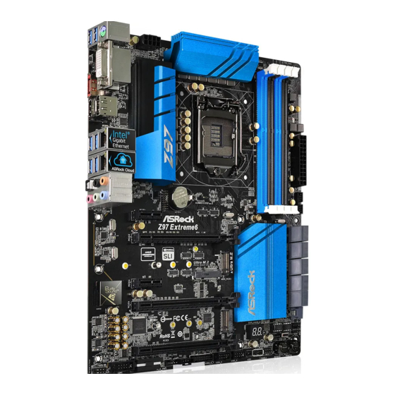
Seite 3: Motherboard-Layout
Z97 Extreme6 Motherboard Layout PWR_FAN1 ATX12V1 CPU_FAN2 CPU_FAN1 CLRC BTN1 USB 3.0 Top: T: USB3 RJ-45 B: USB4 USB 3.0 Top: T: USB1 RJ-45 B: USB2 TPMS1 CHA_FAN3 CMOS Battery CLRMOS1 PCIE1 Z97 Extreme6 PCIE2 Ultra M.2 PCIe Gen3 x4... - Seite 4 No. Description ATX 12V Power Connector (ATX12V1) CPU Fan Connector (CPU_FAN1) CPU Fan Connector (CPU_FAN2) 2 x 240-pin DDR3 DIMM Slots (DDR3_A1, DDR3_B1) 2 x 240-pin DDR3 DIMM Slots (DDR3_A2, DDR3_B2) Power Fan Connector (PWR_FAN1) ATX Power Connector (ATXPWR1) USB 3.0 Header (USB3_4_5) Clear CMOS Jumper (CLRCMOS1) SATA3 Connectors (SATA3_A3_A4) SATA3 Connectors (SATA3_A1_A2)
- Seite 5 Z97 Extreme6 I/O Panel No. Description No. Description PS/2 Mouse/Keyboard Port Optical SPDIF Out Port DVI-I Port USB 3.0 Ports (USB31_12) DisplayPort 1.2 (ASMedia ASM1042AE) LAN RJ-45 Port (Intel® I218V)* USB 3.0 Ports (USB3_34) LAN RJ-45 Port (Realtek RTL8111GR)* (Intel® Z97) (USB3 Hub)
- Seite 6 * There are two LEDs on each LAN port. Please refer to the table below for the LAN port LED indications. ACT/LINK LED SPEED LED LAN Port Activity / Link LED Speed LED Status Description Status Description No Link 10Mbps connection Blinking Data Activity Orange...
-
Seite 7: Chapter 1 Introduction
If you require technical support related to this mother- board, please visit our website for specific information about the model you are using. You may find the latest VGA cards and CPU support list on ASRock’s website as well. ASRock website http://www.asrock.com. -
Seite 8: Specifications
• Dual-Stack MOSFET (DSM) • NexFET™ MOSFET • 12K Platinum Caps (100% Japan made high quality conductive polymer capacitors) • Sapphire Black PCB ASRock Ultra M.2 (PCIe Gen3 x4) ASRock HDD Saver Technology ASRock Full Spike Protection ASRock Cloud ASRock APP Shop • Supports 4... - Seite 9 Z97 Extreme6 • 2 x PCI Express 3.0 x16 Slots (PCIE2/PCIE4: single at x16 Expansion Slot (PCIE2); dual at x8 (PCIE2) / x8 (PCIE4)) * If M2_1 slot is occupied, PCIE2 slot will run at x8 mode, and PCIE4 slot will run at x4 mode.
- Seite 10 • 7.1 CH HD Audio with Content Protection (Realtek Audio ALC1150 Audio Codec) • Premium Blu-ray Audio support • Supports Surge Protection (ASRock Full Spike Protection) • Supports Purity Sound™ 2 - Nichicon Fine Gold Series Audio Caps - 115dB SNR DAC with Differential Amplifier - TI®...
- Seite 11 Storage (RAID 0, RAID 1, RAID 5, RAID 10, Intel Rapid Storage Technology 13 and Intel Smart Response Technology), NCQ, AHCI, Hot Plug and ASRock HDD Saver Technology • 4 x SATA3 6.0 Gb/s Connectors by ASMedia ASM1061, support NCQ, AHCI, Hot Plug and ASRock HDD Saver...
- Seite 12 • 1 x Thunderbolt AIC Connector • 2 x USB 2.0 Headers (support 4 USB 2.0 ports) (Supports ESD Protection (ASRock Full Spike Protection)) • 1 x Vertical Type A USB 2.0 • 2 x USB 3.0 Headers (support 4 USB 3.0 ports) (Supports ESD Protection (ASRock Full Spike Protection)) • 1 x Dr.
- Seite 13 Due to limitation, the actual memory size may be less than 4GB for the reservation for sys- tem usage under Windows® 32-bit operating systems. Windows® 64-bit operating systems do not have such limitations. You can use ASRock XFast RAM to utilize the memory that Windows® cannot use.
-
Seite 14: Unique Features
ASRock Cloud ASRock partners with Kloudian to make your mobile devices connect to your PC seamlessly! ASRock Cloud allows you to get connected with your PC’s files, music, photos, and video clips remotely with tablets anytime, anywhere. - Seite 15 ASRock APP Charger Simply by installing the ASRock APP Charger makes your iPhone/iPad/iPod Touch charge up to 40% faster than before on your computer. ASRock APP Charger allows you to quickly charge many Apple devices simultaneously and even supports continuous charging when your PC enters into Standby mode (S1), Suspend to RAM (S3), hibernation mode (S4) or power off (S5).
- Seite 16 Windows® 8 brings the ultimate boot up experience. The lightning boot up speed makes it hard to access the UEFI setup. ASRock Restart to UEFI allows users to enter the UEFI automatically when turning on the PC. By enabling this function, the PC will enter the UEFI directly after you restart.
- Seite 17 Z97 Extreme6 ASRock Crashless BIOS ASRock Crashless BIOS allows users to update their BIOS without fear of failing. If power loss occurs during the BIOS updating process, ASRock Crashless BIOS will automatically finish the BIOS update procedure after regaining power. Please note that BIOS files need to be placed in the root directory of your USB disk.
-
Seite 18: Chapter 2 Installation
Chapter 2 Installation This is an ATX form factor motherboard. Before you install the motherboard, study the configuration of your chassis to ensure that the motherboard fits into it. Pre-installation Precautions Take note of the following precautions before you install motherboard components or change any motherboard settings. -
Seite 19: Installing The Cpu
Z97 Extreme6 2.1 Installing the CPU 1. Before you insert the 1150-Pin CPU into the socket, please check if the PnP cap is on the socket, if the CPU surface is unclean, or if there are any bent pins in the socket. Do not force to insert the CPU into the socket if above situation is found. - Seite 21 Z97 Extreme6 Please save and replace the cover if the processor is removed. The cover must be placed if you wish to return the motherboard for after service.
- Seite 22 2.2 Installing the CPU Fan and Heatsink...
- Seite 23 Z97 Extreme6 2.3 Installing Memory Modules (DIMM) This motherboard provides four 240-pin DDR3 (Double Data Rate 3) DIMM slots, and supports Dual Channel Memory Technology. 1. For dual channel configuration, you always need to install identical (the same brand, speed, size and chip-type) DDR3 DIMM pairs.
- Seite 25 Z97 Extreme6 2.4 Expansion Slots (PCI Express Slots) There are 5 PCI Express slots and 1 mini-PCI Express slot on the motherboard. Before installing an expansion card, please make sure that the power supply is switched off or the power cord is unplugged. Please read the documentation of the expansion card and make necessary hardware settings for the card before you start the installation.
- Seite 26 2.5 Jumpers Setup The illustration shows how jumpers are setup. When the jumper cap is placed on the pins, the jumper is “Short”. If no jumper cap is placed on the pins, the jumper is “Open”. The illustration shows a 3-pin jumper whose pin1 and pin2 are “Short” when a jumper cap is placed on these 2 pins.
- Seite 27 Z97 Extreme6 2.6 Onboard Headers and Connectors Onboard headers and connectors are NOT jumpers. Do NOT place jumper caps over these headers and connectors. Placing jumper caps over the headers and connectors will cause permanent damage to the motherboard. System Panel Header...
- Seite 28 Power LED Header Please connect the chassis (3-pin PLED1) power LED to this header PLED- PLED+ PLED+ (see p.1, No. 18) to indicate the system’s power status. Serial ATA3 Connectors These ten SATA3 (SATA3_0_3: connectors support SATA see p.1, No. 12) data cables for internal (SATA3_1_4: storage devices with up...
- Seite 29 Z97 Extreme6 USB 2.0 Headers There are two headers USB_PWR (9-pin USB2_3) and one port on this DUMMY (see p.1, No. 25) motherboard. Each USB (9-pin USB4_5) 2.0 header can support (see p.1, No. 26) two ports. USB_PWR (USB1) (see p.1, No. 24) USB 3.0 Headers...
- Seite 30 1. High Definition Audio supports Jack Sensing, but the panel wire on the chassis must sup- port HDA to function correctly. Please follow the instructions in our manual and chassis manual to install your system. 2. If you use an AC’97 audio panel, please install it to the front panel audio header by the steps below: A.
- Seite 31 Z97 Extreme6 ATX Power Connector This motherboard pro- (24-pin ATXPWR1) vides a 24-pin ATX power (see p.1, No. 7) connector. To use a 20-pin ATX power supply, please plug it along Pin 1 and Pin ATX 12V Power This motherboard pro-...
- Seite 32 TPM Header This connector supports Trusted (17-pin TPMS1) Platform Module (TPM) system, (see p.1, No. 33) which can securely store keys, digital certificates, passwords, and data. A TPM system also helps enhance network security, protects digital identities, and ensures platform integrity.
-
Seite 33: Smart Switches
Z97 Extreme6 2.7 Smart Switches The motherboard has four smart switches: Power Switch, Reset Switch, Clear CMOS Switch and one BIOS Selection Switch, allowing users to quickly turn on/off the system, reset the system, clear the CMOS values or boot from different BIOS. - Seite 34 2.8 Dr. Debug Dr. Debug is used to provide code information, which makes troubleshooting even easier. Please see the diagrams below for reading the Dr. Debug codes. Code Description Please check if the CPU is installed correctly and then clear CMOS.
- Seite 35 Z97 Extreme6 Problem related to USB devices. Please try removing all USB devices. Problem related to memory. Please re-install the CPU and memory then clear CMOS. If the problem still exists, please install only one memory module or try using other memory modules.
- Seite 36 2.9 M.2_SSD (NGFF) Module Installation Guide The M.2, also known as the Next Generation Form Factor (NGFF), is a small size and versatile card edge connector that aims to replace mPCIe and mSATA. The Ultra M.2 Socket (M2_1), supports M.2 PCI Express module up to Gen3 x4 (32 Gb/s). The M.2_SSD (NGFF) Socket 3 (M2_2) can accommodate either a M.2 SATA3 6.0 Gb/s module or a M.2 PCI Express module up to Gen 2 x2 (10 Gb/s).
- Seite 37 Z97 Extreme6 Step 3 Move the standoff based on the module type and length. The standoff is placed at the nut location D by default. Skip Step 3 and 4 and go straight to Step 5 if you are going to use the default nut.
- Seite 38 Plextor PX-AG256M6e ADATA AXNS381E-128GM-B Plextor PX-AG512M6e ADATA AXNS381E-256GM-B SanDisk SD6PP4M-128G Crucial CT120M500SSD4/120G SanDisk SD6PP4M-256G Crucial CT240M500SSD4/240G Samsung XP941-512G (MZHPU512HCGL) Intel SSDSCKGW080A401/80G Kingston RBU-SNS8400S3/180GD For the latest updates of M.2_SSD (NFGG) module support list, please visit our website for details: http://www.asrock.com...
-
Seite 39: Connection Diagram
Z97 Extreme6 2.10 HDD Saver Cable Installation Guide The HDD Saver Connector on this motherboard allows you to switch on and off the connected HDDs via software when needed. This design secures more privacy, saves more energy, and extends the HDDs' lifespans. Please follow the steps below to install the HDD Saver Cable. - Seite 40 1 Einleitung Vielen Dank, dass Sie sich für das Z97 Extreme6 von ASRock entschieden haben – ein zuverlässiges Motherboard, das konsequent unter der strengen Qualitätskontrolle von ASRock hergestellt wurde. Es liefert ausgezeichnete Leistung mit robustem Design, das ASRocks Streben nach Qualität und Beständigkeit erfüllt.
-
Seite 41: Technische Daten
• Dual-Stack-MOSFET (DSM) • NexFET™-MOSFET • 12K-Platinkappen (100 % in Japan gefertigt, hochqualitative leitfähige Polymer-Kondensatoren) • Saphirschwarze Leiterplatte ASRock Ultra M.2 (PCIe Gen3 x 4) ASRock HDD-Saver-Technologie ASRock Full Spike Protection ASRock Cloud ASRock App-Shop • Unterstützt Intel® CoreTM-Prozessoren (Sockel 1150) der 4 Prozessor &... - Seite 42 • 2 x PCI-Express 3.0-x16-Steckplätze (PCIE2/PCIE4:einzeln Erweite- bei x16 (PCIE2); doppelt bei x8 (PCIE2) / x8 (PCIE4)) rungss- * Falls der M2_1-Steckplatz belegt ist, läuft der PCIE2- teckplatz Steckplatz im x8-Modus und der PCIE4-Steckplatz im x4- Modus. • 1 x PCI-Express 2.0-x16-Steckplatz (PCIE5:x2-Modus) • 2 x PCI-Express 2.0-x1-Steckplätze • 1 x Mini-PCI-Express-Steckplatz *Mini-PCI-Express-Steckplatz mit PCIE3-Steckplatz geteilt.
- Seite 43 Rück- • 1 x DVI-I-Port blende, • 1 x HDMI-Port • 1 x DisplayPort 1.2 • 1 x Optischer SPDIF-Ausgang • 1 x eSATA-Anschluss • 2 x USB 3.0-Ports (ASMedia ASM1042AE) (unterstützt Schutz gegen elektrostatische Entladung (ASRock Full Spike Protection))
- Seite 44 • 4 x USB 3.0-Ports (Intel® Z97) (unterstützt Schutz gegen elektrostatische Entladung (ASRock Full Spike Protection)) • 2 x RJ-45-LAN-Port mit LED (Aktivität/Verbindung-LED und Geschwindigkeit-LED) • 1 x CMOS-löschen-Schalter • HD-Audioanschlüsse: Hintere Lautsprecher / Zentral / Bass / Line-in / Vorderer Lautsprecher / Mikrofon • 6 x SATA-III-6,0-Gb/s-Anschlüsse per Intel®...
- Seite 45 • 1 x Audioanschluss an Frontblende • 1 x Thunderbolt-Erweiterungskartenanschluss • 2 x USB 2.0-Stiftleisten (unterstützen 4 USB 2.0-Ports) (un- terstützt Schutz gegen elektrostatische Entladung (ASRock Full Spike Protection)) • 1 x Vertikal, Typ A, USB 2.0 • 2 x USB 3.0-Stiftleisten (unterstützen 4 USB 3.0-Ports) (un- terstützt Schutz gegen elektrostatische Entladung (ASRock...
- Seite 46 Aufgrund von Beschränkungen kann die Größe des tatsächlich für die Systemnutzung reservierten Speichers unter Windows®-Betriebssystemen mit 32 Bit weniger als 4 GB betra- gen. Windows®-Betriebssysteme mit 64 Bit haben keine derartigen Beschränkungen. Mit ASRock XFast RAM können Sie den Speicher einsetzen, den Windows® nicht nutzen kann.
-
Seite 47: Jumpereinstellung
Z97 Extreme6 1.3 Jumpereinstellung Die Abbildung zeigt, wie die Jumper eingestellt werden. Wenn die Jumper- Kappe auf den Kontakten angebracht ist, ist der Jumper „kurzgeschlossen“. Wenn keine Jumper-Kappe auf den Kontakten angebracht ist, ist der Jumper „offen“. Die Abbildung zeigt einen 3-poligen Jumper, dessen Kontakt 1 und Kontakt 2 „kurzgeschlossen“... -
Seite 48: Integrierte Stiftleisten Und Anschlüsse
1.4 Integrierte Stiftleisten und Anschlüsse Integrierte Stiftleisten und Anschlüsse sind KEINE Jumper. Bringen Sie KEINE Jumper- Kappen an diesen Stiftleisten und Anschlüssen an. Durch Anbringen von Jumper-Kappen an diesen Stiftleisten und Anschlüssen können Sie das Motherboard dauerhaft beschädi- gen. Systemblende-Stiftleiste Verbinden Sie PLED+ PLED-... - Seite 49 Z97 Extreme6 Betrieb-LED-Stiftleiste Bitte verbinden Sie (3-polig, PLED1) die Betrieb-LED des PLED- PLED+ (siehe S. 1, Nr. 18) Gehäuses zur Anzeige des PLED+ Systembetriebsstatus mit dieser Stiftleiste. Serial-ATA-III- Diese zehn SATA-III- Anschlüsse Anschlüsse unterstützen (SATA3_0_3: SATA-Datenkabel für siehe S. 1, Nr. 12) interne Speichergeräte...
- Seite 50 (USB1) (siehe S. 1, Nr. 24) USB 3.0-Stiftleisten Neben sechs USB Vbus Vbus Vbus IntA_PB_SSRX- (19-polig, USB3_4_5) 3.0-Ports an der E/ IntA_PA_SSRX- IntA_PB_SSRX+ (siehe S. 1, Nr. 8) IntA_PA_SSRX+ A-Blende befinden sich IntA_PB_SSTX- zwei Stiftleisten an diesem IntA_PA_SSTX- IntA_PB_SSTX+ IntA_PA_SSTX+ Motherboard.
- Seite 51 Z97 Extreme6 Gehäuselautsprecherstift- Bitte verbinden Sie den DUMMY SPEAKER leiste Gehäuselautsprecher mit (4-polig, SPEAKER1) dieser Stiftleiste. DUMMY (siehe S. 1, Nr. 17) Gehäuse- und Netz- Bitte verbinden Sie die +12V teillüfteranschlüsse Lüfterkabel mit den CHA_FAN_SPEED (4-polig, CHA_FAN1) Lüfteranschlüssen; der FAN_SPEED_CONTROL (siehe S.
- Seite 52 ATX-12-V-Netzanschluss Dieses Motherboard (8-polig, ATX12V1) bietet einen 8-poligen (siehe S. 1, Nr. 1) ATX-12-V-Netzanschluss. Bitte schließen Sie es zur Nutzung eines 4-poligen ATX-Netzteils entlang Kontakt 1 und Kontakt 5 PCIe-Netzanschluss Bitte verbinden Sie ein 4-poliges (4-polig, PCIE_PWR1) Molex-Netzkabel mit diesem (siehe S.
-
Seite 53: Intelligente Schalter
Z97 Extreme6 1.5 Intelligente Schalter Das Motherboard hat vier intelligente Schalter: Ein-/Ausschalter, Reset-Schalter, CMOS-löschen-Schalter und ein BIOS-Auswahlschalter, wodurch Benutzer das System schnell ein-/abschalten, zurücksetzen, die CMOS-Werte löschen oder von einem anderen BIOS starten können. Ein-/Ausschalter Mit dem Ein-/Ausschalter (PWRBTN) kann der Benutzer das Power (siehe S. -
Seite 54: Contenu De L'emballage
à modification sans préavis. En cas de modifications du présent document, la version mise à jour sera disponible sur le site Internet ASRock sans notification préalable. Si vous avez besoin d’une assistance technique pour votre carte mère, veuillez visiter notre site Internet pour plus de détails sur le modèle que vous utilisez. -
Seite 55: Spécifications
• Conception Digi Power • Alimentation à 12 phases • Prend en charge la technologie Intel® Turbo Boost 2.0 • Prend en charge les processeurs débloqués de la série K Intel® • Prend en charge l’overclocking ASRock BCLK Full-range • Intel ® Chipset • Technologie mémoire double canal DDR3... - Seite 56 • 2 x fentes PCI Express 3.0 x 16 (PCIE2/PCIE4 :simple à x16 Fente (PCIE2) ; double à x8 (PCIE2) / x8 (PCIE4)) d’expan- * Si la fente M2_1 est occupée, la fente PCIE2 fonctionnera sion en mode x8 et la fente PCIE4 en mode x4. • 1 x fente PCI Express 2.0 x16 (PCIE5 :mode x2) • 2 x fentes PCI Express 2.0 x1 • 1 x fente mini-PCI Express...
- Seite 57 • Prise en charge du réveil sur LAN (sur Realtek RTL8111GR) • Prend en charge la fonction Wake-On-LAN • Protection contre les orages/décharges électrostatiques (Pro- tection complète contre les pics ASRock) • Prise en charge de la détection des câbles LAN (sur Realtek RTL8111GR) • Prend en charge la fonction d’économie d’énergie Ethernet...
- Seite 58 • 4 x connecteurs SATA3 6,0 Go/s par ASMedia ASM1061, compatibles avec les fonctions NCQ, AHCI, « Hot Plug » et de sauvegarde HDD ASRock (le connecteur SATA3_A4 est partagé avec le port eSATA) • 1 x connecteur SATA Express (partagé avec SATA3_4, SATA3_5 et M.2_SSD (NGFF) socket 3 (M2_2))
- Seite 59 • 2 x embases USB 2.0 (4 ports USB 2.0 pris en charge) (Pro- tection contre les décharges électrostatiques (Protection complète contre les pics ASRock)) • 1 x port USB 2.0 type A vertical • 2 x embases USB 3.0 (4 ports USB 3.0 pris en charge) (Pro- tection contre les décharges électrostatiques (Protection...
- Seite 60 * pour des informations détaillées de nos produits, veuillez visiter notre site : http://www.asrock.com Il est important de signaler que l'overcloking présente certains risques, incluant des modifications du BIOS, l’application d’une technologie d’overclocking déliée et l'utilisation d'outils d'overclocking développés par des tiers. La stabilité de votre système peut être affec- tée par ces pratiques, voire provoquer des dommages aux composants et aux périphériques...
- Seite 61 Z97 Extreme6 1.3 Configuration des cavaliers (jumpers) L’illustration ci-dessous vous renseigne sur la configuration des cavaliers (jumpers). Lorsque le capuchon du cavalier est installé sur les broches, le cavalier est « court- circuité ». Si le capuchon du cavalier n’est pas installé sur les broches, le cavalier est « ouvert ».
- Seite 62 1.4 Embases et connecteurs de la carte mère Les embases et connecteurs situés sur la carte NE SONT PAS des cavaliers. Ne placez JAMAIS de capuchons de cavaliers sur ces embases ou connecteurs. Placer un capuchon de cavalier sur ces embases ou connecteurs endommagera irrémédiablement votre carte mère. Embase du panneau Branchez le bouton PLED+...
- Seite 63 Z97 Extreme6 Embase LED Veuillez brancher le LED d’alimentation d’alimentation du châssis PLED- PLED+ (PLED1 à 3 broches) sur cette embase pour PLED+ (voir p.1, No. 18) indiquer l’état d’alimenta- tion du système. Connecteurs Serial ATA3 Ces dix connecteurs (SATA3_0_3: SATA3 sont compatibles (voir p.1, No.
- Seite 64 (USB1) (voir p.1, No. 24) Embases USB 3.0 En plus des deux ports Vbus Vbus Vbus IntA_PB_SSRX- (USB3_4_5 à 19 broches) USB 3.0 sur le panneau IntA_PA_SSRX- IntA_PB_SSRX+ IntA_PA_SSRX+ (voir p.1, No. 8) E/S, cette carte mère est IntA_PB_SSTX- dotée de deux embases. IntA_PA_SSTX- IntA_PB_SSTX+ IntA_PA_SSTX+...
- Seite 65 Z97 Extreme6 Embase du haut-parleur Veuillez brancher le haut- DUMMY SPEAKER du châssis parleur du châssis sur (SPEAKER1 à 4 broches) cette embase. DUMMY (voir p.1, No. 17) Connecteurs du châssis Veuillez brancher les et de l’alimentation du câbles du ventilateur...
- Seite 66 Connecteur Cette carte mère est d’alimentation ATX 12V dotée d’un connecteur (ATX12V1 à 8 broches) d’alimentation ATX 12V (voir p.1, No. 1) à 8 broches. Pour utiliser une alimentation ATX à 4 broches, veuillez effectuer les branchements sur la Broche 1 et la Broche 5. Connecteur Veuillez connecter un câble d'alimentation PCIe...
- Seite 67 Z97 Extreme6 1.5 Boutons intelligents La carte mère est équipée de quatre boutons intelligents : bouton de mise en marche, bouton de réinitialisation, bouton d’effacement CMOS et bouton de sélecteur de BIOS qui permettent aux utilisateurs d’allumer/éteindre le système, de réinitialiser le système, d’effacer les valeurs CMOS en toute simplicité...
-
Seite 68: Contenuto Della Confezione
Nel caso di eventuali modifiche della presente documentazione, la versione aggiornata sarà disponi- bile sul sito Web di ASRock senza ulteriore preavviso. Per il supporto tecnico correlato a questa scheda madre, visitare il nostro sito Web per informazioni specifiche relative al modello attualmente in uso. - Seite 69 100% in Giappone) • PCB Sapphire Black ASRock Ultra M.2 (PCIe Gen3 x4) Tecnologia ASRock HDD Saver Protezione completa ASRock dai picchi di corrente ASRock Cloud APP Shop ASRock • Supporta processori 4 Gen e 5 Generation Intel®...
- Seite 70 • 2 x Alloggi PCI Express 3.0 x16 (PCIE2/PCIE4:modalità Slot di es- singola a x16 (PCIE2); doppia a x8 (PCIE2) / x8 (PCIE4)) pansione * Se l’alloggio M2_1 è occupato, l’alloggio PCIE2 funzionerà a modalità x8 e l’alloggio PCIE4 funzionerà a modalità x4. • 1 x Alloggio PCI Express 2.0 x16 (PCIE5:modalità...
- Seite 71 • Supporto di Wake-On-WAN (su Realtek RTL8111GR) • Supporta Wake-On-LAN • Supporto la protezione da fulmini/scariche elettrostatiche (ESD) (protezione completa ASRock dai picchi di corrente) • Supporto del rilevamento cavo LAN (su Realtek RTL8111GR) • Supporta Energy Efficient Ethernet 802.3az • Supporta PXE...
- Seite 72 Technology 13 e Intel Smart Response Technology), NCQ, AHCI, Hot Plug e tecnologia ASRock HDD Saver • 4 x Connettori SATA3 6,0Gb/s ASMedia ASM1061, sup- portano NCQ, AHCI, Hot Plug e la tecnologia ASRock HDD Saver (il connettore SATA3_A4 è condiviso con la porta eSATA) • 1 x Connettore SATA Express (condiviso con SATA3_4,...
- Seite 73 • 2 x Collettori USB 2.0 (supporto di 4 porte USB 2.0) (suppor- to protezione da scariche elettrostatiche (ESD) (protezione completa ASRock dai picchi di corrente)) • 1 x USB 2.0 verticale tipo A • 2 x Collettori USB 3.0 (supporto di 4 porte USB 3.0) (suppor-...
- Seite 74 * Per informazioni dettagliate sul prodotto, visitare il nostro sito Web: http://www.asrock.com Prestare attenzione al potenziale rischio previsto nella pratica di overclocking, inclusa la regolazione delle impostazioni nel BIOS, l'applicazione di tecnologia di Untied Overclock- ing o l'utilizzo di strumenti di overclocking di terze parti. L'overclocking può influenzare la stabilità...
- Seite 75 Z97 Extreme6 1.3 Impostazione jumper L'illustrazione mostra in che modo vengono impostati i jumper. Quando il cappuccio del jumper è posizionato sui pin, il jumper è "cortocircuitato". Se sui pin non è posizionato alcun cappuccio del jumper, il jumper è "aperto". L'illustrazione mostra un jumper a 3 pin i cui pin1 e pin2 sono "cortocircuitati"...
- Seite 76 1.4 Header e connettori sulla scheda Gli header e i connettori sulla scheda NON sono jumper. NON posizionare cappucci del jumper su questi header e connettori. Il posizionamento di cappucci del jumper su header e connettori provocherà danni permanenti alla scheda madre. Header sul pannello del Collegare l'interruttore PLED+...
- Seite 77 Z97 Extreme6 Header LED di Collegare il LED di alimentazione alimentazione chassis a PLED- PLED+ (PLED1 a 3 pin) questo header per indicare PLED+ (vedere pag. 1, n. 18) lo stato di alimentazione del sistema. Connettori Serial ATA3 Questi dieci connettori...
- Seite 78 (USB1) (vedere pag. 1, n. 24) Header USB 3.0 Oltre alle sei porte USB 3.0 Vbus Vbus Vbus IntA_PB_SSRX- (USB3_4_5 a 19 pin) del pannello I/O, questa IntA_PA_SSRX- IntA_PB_SSRX+ IntA_PA_SSRX+ (vedere pag. 1, n. 8) scheda madre è dotata di IntA_PB_SSTX- IntA_PA_SSTX- IntA_PB_SSTX+...
- Seite 79 Z97 Extreme6 Header altoparlante chas- Collegare l'altoparlante DUMMY SPEAKER dello chassis a questo (SPEAKER1 a 4 pin) header. DUMMY (vedere pag. 1, n. 17) Connettori ventola dello Collegare i cavi della +12V chassis e di alimentazione ventola ai connettori della...
- Seite 80 Connettore di Questa scheda madre è alimentazione ATX da 12 dotata di un connettore di alimentazione ATX da 12 (ATX12V1 a 8 pin) V a 8 pin. Per utilizzare (vedere pag. 1, n. 1) un'alimentazione ATX a 4 pin, collegarla lungo il pin1 e il pin 5.
- Seite 81 Z97 Extreme6 1.5 Interruttori intuitivi La scheda madre è dotata di quattro interruttori intuitivi: Interruttore d’alimentazione, interruttore di ripristino, interruttore Clear CMOS ed un interruttore di selezione BIOS che consentono di accendere/spegnere rapidamente il sistema, ripristinare il sistema, cancellare i valori CMOS oppure eseguire l’avvio su un BIOS diverso.
-
Seite 82: Contenido Del Paquete
Podrá encontrar las últimas tarjetas VGA, así como la lista de compatibilidad de la CPU, en el sitio web de ASRock. Sitio web de ASRock http://www. asrock.com. -
Seite 83: Especificaciones
• NexFET™ MOSFET • Tapas de platino de 12K (condensadores de polímero conductor de alta calidad, 100% fabricados en Japón) • PCB de zafiro negro ASRock Ultra M.2 (PCIe Gen3 x4) Tecnología de ahorro ASRock HDD Protección ASRock Full Spike ASRock Cloud Tienda de aplicaciones ASRock • Compatible con 4... - Seite 84 • 2 ranuras PCI Express 3.0 x16 (PCIE2/PCIE4:simple a x16 Ranura de (PCIE2); dual a x8 (PCIE2) / x8 (PCIE4)) expansión * Si la ranura M2_1 estuviera ocupada, la ranura PCIE2 se ejecutará en modo x8, y PCIE4 se ejecutará en modo x4. • 1 ranura PCI Express 2.0 x16 (PCIE5:modo x2) • 2 ranuras PCI Express 2.0 x1 • 1 ranura Express mini-PCI...
- Seite 85 • 1 puerto DVI-I trasero I/O • 1 puerto HDMI • 1 DisplayPort 1.2 • 1 puerto de salida SPDIF óptica • 1 conector eSATA • 2 puertos USB 3.0 (ASMedia ASM1042AE) (compatible con protección contra electricidad estática (protección ASRock Full Spike))
- Seite 86 • 4 conectores SATA3 de 6,0 Gb/s de ASMedia ASM1061, com- patibles con NCQ, AHCI, Hot Plug y tecnología de ahorro ASRock HDD (el conector SATA3_A4 se comparte con el puerto eSATA) • 1 conector express SATA (compartido con SATA3_4, SATA3_5 y Socket 3 M.2_SSD (NGFF) (M2_2))
- Seite 87 • 2 cabezales USB 2.0 (compatible con 4 puertos USB 2.0) (compatible con protección contra electricidad estática (pro- tección ASRock Full Spike)) • 1 USB 2.0 vertical de tipo A • 2 cabezales USB 3.0 (compatible con 4 puertos USB 3.0) (compatible con protección contra electricidad estática (pro-...
- Seite 88 * Para obtener más información acerca del producto, visite nuestro sitio web: http://www.asrock.com Tenga en cuenta que existen ciertos riesgos relacionados con el overclocking (sobreacel- eración), incluyendo el ajuste de la configuración del BIOS, aplicando la Tecnología overcloking no vinculada o utilizando las herramientas de overclocking de tercera parte. El overclocking podría afectar la estabilidad de su sistema o incluso dañar los componentes y...
- Seite 89 Z97 Extreme6 1.3 Instalación de los puentes La instalación muestra cómo deben instalarse los puentes. Cuando la tapa de puente se coloca en los pines, el puente queda “Corto”. Si no coloca la tapa de puente en los pines, el puente queda “Abierto”. La ilustración muestra un puente de 3 pines cuyo pin 1 y pin 2 son “Cortos”...
- Seite 90 1.4 Conectores y cabezales incorporados Los cabezales y conectores incorporados NO son puentes. NO coloque tapas de puente sobre estos cabezales y conectores. Si coloca tapas de puente sobre los cabezales y conectores dañará de forma permanente la placa base. Cabezal del panel del Conecte el interruptor PLED+...
- Seite 91 Z97 Extreme6 Cabezal de indicador LED Conecte el indicador LED de alimentación de alimentación del chasis PLED- PLED+ (PLED1 de 3 pines) a este cabezal para indicar PLED+ (consulte la pág.1, N.º 18) el estado de alimentación del sistema. Conectores Serie ATA3...
- Seite 92 (USB1) (consulte la pág.1, N.º 24) Cabezales USB 3.0 Además de seis puertos Vbus Vbus Vbus IntA_PB_SSRX- (USB3_4_5 de 19 pines) USB 3.0 en el panel de E/S, IntA_PA_SSRX- IntA_PB_SSRX+ IntA_PA_SSRX+ (consulte la pág.1, N.º 8) esta placa base cuenta con IntA_PB_SSTX- IntA_PA_SSTX- IntA_PB_SSTX+...
- Seite 93 Z97 Extreme6 Cabezal de altavoces del Conecte el altavoz del DUMMY SPEAKER chasis chasis a este cabezal. (SPEAKER1 de 4 pines) DUMMY (consulte la pág.1, N.º 17) Conectores del ventilador Conecte los cables del +12V CHA_FAN_SPEED de alimentación y del cha-...
- Seite 94 Conector de alimentación Esta placa base contiene ATX de 12V un conector de alimentac- (ATX12V1 de 8 pines) ión ATX de 12V y 8 pines. (consulte la pág.1, N.º 1) Para utilizar una toma de alimentación ATX de 4 pines, conéctela en los Pines del 1 al 5.
- Seite 95 Z97 Extreme6 1.5 Interruptores inteligentes La placa base contiene cuatro interruptores inteligentes: Interruptor de alimentación, interruptor de reseteo, interruptor de borrado de CMOS y un interruptor de selección BIOS, que permiten a los usuarios encender y apagar rápidamente el sistema, resetearlo, borrar los valores de CMOS, o arrancar desde un BIOS diferente.
-
Seite 96: Комплект Поставки
уведомления. При необходимости технической поддержки, связанной с материнской платой, посетите веб-сайт и найдите на нем информацию о модели используемой вами материнской платы. На веб-сайте ASRock также можно найти самый последний перечень поддерживаемых VGA-карт и ЦП. Веб-сайт ASRock http://www.asrock.com. 1.1 Комплект поставки... - Seite 97 • Конденсаторы 12K Platinum (с использованием высококачественных конденсаторов из проводящих полимеров производства Японии) • Печатная плата Sapphire Black ASRock Ultra M.2 (PCIe Gen3 x4) Технология ASRock HDD Saver Технология полной защиты от импульсных пиков напряжения ASRock Full Spike Protection ASRock Cloud Веб-магазин...
- Seite 98 • 2 x Слот PCI Express 3.0 x16 (PCIE2/PCIE4:один x16 Слот (PCIE2); два x8 (PCIE2) / x8 (PCIE4)) расширения * Если слот M2_1 занят, слот PCIE2 используется в режиме x8, а слот PCIE4 используется в режиме x4. • 1 x Слот PCI Express 2.0 x16 (PCIE5:режим x2) • 2 x PCI Express 2.0 x1 разъем...
- Seite 99 • 7.1-канальный звук высокой четкости HD Audio с Аудио защитой данных (аудиокодек Realtek ALC1150) • Поддержка Premium Blu-ray Audio • Защита от перенапряжения (ASRock Full Spike Protection) • Поддержка Purity Sound™ 2 - Конденсаторы для аудиосистем серии Nichicon Fine Gold - 115 дБ...
- Seite 100 RAID 1, RAID 5, RAID 10, Intel Rapid Storage Tech- nology 13 и Intel Smart Response Technology), NCQ, AHCI, "горячего" подключения и ASRock HDD Saver • 4 x Разъем SATA3 со скоростью обмена данными 6,0 ГБ/с с ASMedia ASM1061, технологии NCQ, AHCI, "горячего"...
- Seite 101 • 1 x аудиоразъем на передней панели • 1 x AIC-разъем Thunderbolt • 2 x Колодки USB 2.0 (до 4 портов USB 2.0) с защитой от электростатического напряжения (ASRock Full Spike Protection) • 1 х вертикальный разъем USB 2.0 типа A • 2 x Колодки...
- Seite 102 вызванный разгоном процессора. В связи с ограничением при работе под 32-разрядной ОС Windows® фактический объем памяти может быть меньше 4 Гбайт. Для 64-разрядных ОС Windows® таких ограничений нет. Для использования той памяти, которую ОС Windows® не может использовать, используйте ASRock XFast RAM.
- Seite 103 Z97 Extreme6 1.3 Установка перемычек Установка перемычек показана на рисунке. При установке колпачковой перемычки на контакты перемычка «замкнута». Если колпачковая перемычка на контакты не установлена, перемычка «разомкнута». На рисунке показана 3-контактная перемычка с замкнутыми контактами 1 и 2 при установке на них...
- Seite 104 1.4 Колодки и разъемы, расположенные на материнской плате Расположенные на материнской плате колодки и разъемы перемычками НЕ являются. НЕ устанавливайте на эти колодки и разъемы колпачковые перемычки. Установка колпачковых перемычек на эти колодки и разъемы может вызвать неустранимое повреждение материнской платы. Колодка...
- Seite 105 Z97 Extreme6 Колодка светодиодного Подключите индикатора питания светодиодный индикатор PLED- PLED+ (3-контактная, PLED1) питания корпуса к PLED+ (См. стр. 1, № 18) этой колодке, чтобы обеспечить индикацию состояния питания системы. Разъемы Serial ATA3 Эти десять (SATA3_0_3: разъемов SATA3 См. стр. 1, № 12) предназначены...
- Seite 106 (USB1) (См. стр. 1, № 24) Vbus Vbus Колодки USB 3.0 Помимо шести портов Vbus IntA_PB_SSRX- (19-контактная, USB 3.0, на панели ввода- IntA_PA_SSRX- IntA_PB_SSRX+ IntA_PA_SSRX+ USB3_4_5) вывода материнской IntA_PB_SSTX- (См. стр. 1, № 8) платы имеются две IntA_PA_SSTX- IntA_PB_SSTX+ IntA_PA_SSTX+ колодки.
- Seite 107 Z97 Extreme6 Колодка динамика Предназначена для DUMMY SPEAKER корпуса подключения динамика (4-контактная, SPEAK- корпуса. DUMMY ER1) (См. стр. 1, № 17) Разъемы для Предназначены для +12V вентиляторов корпуса и подключения кабелей CHA_FAN_SPEED блока питания разъемов вентиляторов FAN_SPEED_CONTROL (4-контактный, CHA_ и подключения черного...
- Seite 108 Разъем питания АТХ 12 Эта материнская плата В снабжена 8-контактным (8-контактный, разъемом питания АТХ ATX12V1) 12 В. Чтобы использовать (См. стр. 1, № 1) 4-контактный разъем питания ATX, подключите его вдоль контакта 1 и контакта 5. Разъем питания PCIe При установке более трех (4-контактный...
- Seite 109 Z97 Extreme6 1.5 Электронные кнопки На системной плате размещены четыре электронных переключателя: выключатель питания, кнопка сброса, кнопка очистки КМОП и селекторный переключатель BIOS, позволяющие быстро выключать/выключать систему, сбрасывать систему, очищать параметры КМОП или загружаться с другой BIOS. Кнопка питания Кнопка питания...
-
Seite 110: Conteúdo Da Embalagem
Se precisar de assistência técnica relacionada a esta placa principal, visite o nosso site para obter informações específicas sobre o modelo que estiver utilizando. Você também poderá encontrar a lista de placas VGA e CPU mais recentes suportadas no site da ASRock. Site da ASRock http://www.asrock.com. - Seite 111 • NexFET™ MOSFET • Capas de Platina de 12K (condensadores 100% feitos no Japão de polímero condutivo alta qualidade) • PCB Preto Safira ASRock Ultra M.2 (PCIe Gen3 x4) Tecnologia Protetora de HDD ASRock Proteção Total Contra Picos ASRock ASRock Cloud Loja de Aplicativos ASRock • Suporta 4...
- Seite 112 • 2 x Slots PCI Express 3.0 x16 (PCIE2/PCIE4:único em x16 Slot de expansão (PCIE2); duplo em x8 (PCIE2) / x8 (PCIE4)) * Se slot M2_1 está ocupado, slot PCIE2 irá operar no modo x8, e slot PCIE4 irá operar no modo x4. • 1 x Slot PCI Express 2.0 x16 (PCIE5:modo x2) • 2 x Slots PCI Express 2.0 x1 • 1 x Slot mini-PCI Express...
- Seite 113 • 1 x porta HDMI terior • 1 x DisplayPort 1.2 • 1 x Porta de saída SPDIF ótica • 1 x Conector eSATA • 2 x Portas USB 3.0 (ASMedia ASM1042AE)(Suporta Proteção ESD (Proteção Total Contra Picos ASRock))
- Seite 114 Protetora de HDD ASRock • 4 x Conectores SATA3 6,0 Gb/s ASMedia ASM1061, suporte NCQ, AHCI, Conector a Quente e Tecnologia Protetora de HDD ASRock (O conector SATA3_A4 é compartilhada com a porta eSATA) • 1 x Conector SATA Express (compartilhado com SATA3_4, SATA3_5 e M.2_SSD (NGFF) Soquete 3 (M2_2))
- Seite 115 • 1 x Conector Thunderbolt AIC • 2 x Plataformas USB 2.0 (Suporta 4 portas USB 2.0) (Suporta Proteção ESD (Proteção Total Contra Picos ASRock)) • 1 USB 2.0 Tipo A Vertical • 2 x Plataformas USB 3.0 (Suporta 4 portas USB 3.0) (Suporta Proteção ESD (Proteção Total Contra Picos ASRock))
- Seite 116 * Para obter informações detalhadas sobre o produto, por favor, visite o nosso site: http://www.asrock.com Por favor, observe que existe um certo risco envolvendo overclocking, incluindo o ajuste das definições na BIOS, a aplicação de tecnologia Untied Overclocking ou a utilização de ferra- mentas de overclocking de terceiros.
- Seite 117 Z97 Extreme6 1.3 Configuração dos jumpers A imagem abaixo mostra como os jumpers são configurados. Quando a tampa do jumper é colocada nos pinos, o jumper é "Curto". Se não for colocada uma tampa de jumper nos pinos, o jumper é "Aberto". A imagem mostra um jumper de 3 pinos cujos pino1 e pino2 estão "Curtos"...
- Seite 118 1.4 Suportes e conectores onboard Os conectores e suportes onboard NÃO são jumpers. NÃO coloque tampas de jumpers sobre es- tes terminais e conectores Colocar tampas de jumpers sobre os terminais e conectores irá causar danos permanentes à placa-mãe. Suporte do painel de siste- Ligue o botão de PLED+ PLED-...
- Seite 119 Z97 Extreme6 Suporte LED de Por favor, conecte o LED alimentação de alimentação do chassi PLED- PLED+ (PLED1 de 3 pinos) neste suporte para indicar PLED+ (ver p.1, N.º 18) o estado de alimentação do sistema. Conectores série ATA3 Estes dez conectores...
- Seite 120 (USB1) (ver p.1, N.º 24) Suportes USB 3.0 Além das seis portas Vbus Vbus Vbus IntA_PB_SSRX- (USB3_4_5 de 19 pinos) USB 3.0 no painel de E/S, IntA_PA_SSRX- IntA_PB_SSRX+ (ver p.1, N.º 8) IntA_PA_SSRX+ existem dois suportes nesta IntA_PB_SSTX- placa-mãe. Cada suporte IntA_PA_SSTX- IntA_PB_SSTX+ IntA_PA_SSTX+...
- Seite 121 Z97 Extreme6 Suporte do alto-falante do Por favor, conecte o alto- DUMMY SPEAKER chassi falante do chassi a este DUMMY (SPEAKER1 de 4 pinos) suporte. (ver p.1, N.º 17) Conectores do ventilador Por favor, conecte os +12V do chassi e alimentação...
- Seite 122 Conector de alimentação Esta placa-mãe inclui um de 12V ATX conector de alimentação (ATX12V1 de 8 pinos) de 12V ATX de 8 pinos. (ver p.1, N.º 1) Para utilizar uma fonte de alimentação ATX de 4 pinos, introduza-a no Pino 1 e Pino 5.
- Seite 123 Z97 Extreme6 1.5 Interruptores inteligentes A placa-mãe tem quatro chaves inteligentes: Chave liga/desliga, Chave de Reset, Chave para Limpar CMOS e uma Chave de Seleção da BIOS, que permite aos usuários rapidamente ligar/desligar o sistema, reiniciar o sistema, limpar os valores de CMOS ou inicializar de BIOS diferentes.
-
Seite 124: Ambalaj İçeriği
Rock'ın web sitesinde yer alacaktır.. Bu anakart ile ilgili olarak teknik destek almak istiyorsanız, lütfen kullandığınız model hakkında özel bilgiler için web sitemizi ziyaret edin. En güncel VGA kartları ve CPU destek listelerini de ASRock'ın web sitesinden bulabilirsiniz. ASRock web sitesi http://www.asrock.com. - Seite 125 • Dijital Güç tasarımı • 12 Güç Safhası tasarımı • Intel® Turbo Boost 2.0 Teknolojisini destekler • Intel® K Serisi kilitsiz işlemcileri destekler • ASRock BCLK tam aralıklı Hız Aşırtmayı destekler • Intel ® Yonga kümesi • Çift Kanallı DDR3 Bellek Teknolojisi Bellek • 4 x DDR3 DIMM Yuvası...
- Seite 126 • 2 x PCI Express 3.0 x16 yuva (PCIE2/PCIE4:x16'da (PCIE2) Genişlet- tek; x8'de (PCIE2) / x8'de (PCIE4) çift) me Yuvası * M2_1 yuvası doluysa, PCIE2 yuvası x8 modunda ve PCIE4 yuvası x4 modunda çalışacak. • 1 x PCI Express 2.0 x16 yuva (PCIE5:x2 modu) • 2 x PCI Express 2.0 x1 Yuva • 1 x mini-PCI Express Yuvası...
- Seite 127 • İçerik Koruma Özelliği ile 7.1 CH HD Ses (Realtek ALC1150 Ses Codec Bileşeni) • Üstün Blu-ray Ses desteği • Dalgalanma Koruması Destekler (ASRock Tam Ani Gerilim Koruması) • Purity Sound™ 2 destekler - Nichicon Fine Gold Serisi Ses Kapakları...
- Seite 128 Depolama (RAID 0, RAID 1, RAID 5, RAID 10, Intel Rapid Storage Technology 13 ve Intel Smart Response Technology), NCQ, AHCI, Tak Çıkar ve ASRock Sabit Disk Kaydedici Teknolojisi destekler • 4 x SATA3 6,0 Gb/s Bağlayıcısı, ASMedia ASM1061 tarafından, NCQ, AHCI, Tak Çıkar ve ASRock Sabit Disk Kaydedici Teknolojisi destekler (SATA3_A4 bağlayıcısı...
- Seite 129 • 1 x Ön Panel Ses Bağlayıcısı • 1 x Thunderbolt AIC Bağlayıcısı • 2 x USB 2.0 Bağlantısı (4 USB 2.0 bağlantı noktası destekler) (ESD Koruması Destekler (ASRock Tam Ani Gerilim Koru- ması)) • 1 x Dikey Tip A USB 2.0 • 2 x USB 3.0 Bağlantısı...
- Seite 130 * Detaylı ürün bilgisi için, lütfen web sitemizi ziyaret edin: http://www.asrock.com Lütfen, BIOS ayarlarını düzenleme, Bağımsız Hız Aşırtma Teknolojinin uygulanması ya da üçüncü kişilerin hız aşırtma araçlarının kullanılması da dahil olmak üzere tüm hız aşırtma işlemlerinin belirli bir risk taşıdığını unutmayın. Hız aşırtma, sisteminizin dayanıklılığını...
- Seite 131 Z97 Extreme6 1.3 Bağlantı Teli Kurulumu Çizim, bağlantı tellerinin kurulumunu göstermektedir. Tel kapağı, pimlerin üzerine yerleştirildiğinde, tel "Kısa" olur. Pimlerin üzerinde tel kapağı bulunmadığında, tel "Kısa" olur. Çizim, pin1 ve pin2 alanları "Kısa" olan ve bu iki pim üzerinde bir bağlantı...
- Seite 132 1.4 Ekli Bağlantılar ve Bağlayıcılar Ekli bağlantılar ve bağlayıcılar bağlantı teli değildir. Bağlantı teli kapaklarını bu bağlantı ve bağlayıcılar üzerine yerleştirmeyin. Bağlantı teli kapaklarının bağlantılar ile bağlayıcılar üzerine yerleştirilmesi, anakarta kalıcı hasar verebilir. Sistem Paneli Bağlantısı Güç anahtarını bağlayın, PLED+ PLED- (9-pin PANEL1) kasa üzerindeki anahtar ile...
- Seite 133 Z97 Extreme6 Güç LED Bağlantısı Sistemin güç durumunun (3-pin PLED1) belirtilmesi için lütfen PLED- PLED+ PLED+ (bkz. sf.1, No. 18) güç LED'ini bu bağlantıya takın. Seri ATA3 Bağlayıcıları Bu on SATA3 bağlayıcısı, (SATA3_0_3: veri aktarım hızı 6,0 Gb/ bkz. sf.1, No. 12)
- Seite 134 (USB1) (bkz. sf.1, No. 24) USB 3.0 Bağlantıları Bu anakart üzerinde, G/Ç Vbus Vbus Vbus IntA_PB_SSRX- (19-pin USB3_4_5) paneli üzerindeki altı USB IntA_PA_SSRX- IntA_PB_SSRX+ IntA_PA_SSRX+ (bkz. sf.1, No. 8) 3.0 bağlantı noktasının IntA_PB_SSTX- IntA_PA_SSTX- IntA_PB_SSTX+ yanı sıra iki adet bağlantı IntA_PA_SSTX+ IntA_PB_D- bulunmaktadır.
- Seite 135 Z97 Extreme6 Kasa Hoparlör Bağlantısı Lütfen kasa hoparlörünü DUMMY SPEAKER (4-pin SPEAKER1) bu bağlantıya takın. DUMMY (bkz sf.1, No. 17) Kasa ve Güç Fanı Lütfen fan kablolarını +12V Bağlayıcıları fan bağlayıcılarına takın CHA_FAN_SPEED FAN_SPEED_CONTROL (4-pin CHA_FAN1) ve siyah teli topraklama (bkz sf.1, No.
- Seite 136 ATX 12V Güç Bağlayıcısı Bu anakart, 8-pin ATX (8-pin ATX12V1) 12V güç bağlayıcısı (bkz. sf.1, No. 1) sağlamaktadır. 4-pin ATX güç beslemesi kullanmak için, lütfen Pin 1 ve Pin 5'e bağlayın. PCIe Güç Bağlayıcısı Üçten fazla grafik kartı (4 pimli PCIE_PWR1) takıldığında, lütfen bu bağlayıcıya (bkz.
- Seite 137 Z97 Extreme6 1.5 Akıllı Anahtar Anakartta dört adet akıllı düğme bulunur: Güç Düğmesi, Sıfırlama Düğmesi, CMOS Temizleme Düğmesi ve bir BIOS Seçim Anahtarı kullanıcıların sistemi hızlı bir şekilde açıp kapatmalarını, sistemi sıfırlamalarını, CMOS değerlerini temizlemelerini ya da farklı BIOS'tan yüklemelerini sağlar.
- Seite 138 1 개요 ASRock Z97 Extreme6 마더보드를 구입해 주셔서 감사합니다 . 이 마더보드는 ASRock 의 일관되고 엄격한 품질관리 하에 생산되어 신뢰성이 우수합니다 . 품 질과 내구성에 대한 ASRock 의 기준에 부합하는 우수한 성능과 견고한 설계를 제공합니다 . 마더보드 규격과 BIOS 소프트웨어를 업데이트할 수도 있기 때문에 , 이 설명서의...
- Seite 139 • 듀얼 스택 MOSFET (DSM) • NexFET ™ MOSFET • 12K 백금 캡 (100% 일본산 고품질 전도성 폴리머 콘덴서 ) • 사파이어 블랙 PCB ASRock Ultra M.2 (PCIe Gen3 4 개 ) ASRock HDD 세이버 기술 ASRock 풀 스파이크 보호 ASRock Cloud ASRock 앱...
- Seite 140 • PCI Express 3.0 x16 슬롯 2 개 (PCIE2/PCIE4: 단일 @ x16 확장 슬롯 (PCIE2), 이중 @ x8 (PCIE2) / x8 (PCIE4)) * M2_1 슬롯이 사용되고 있을 경우 PCIE2 슬롯은 x8 모드 로 동작하고 PCIE4 슬롯은 x4 모드에서 동작합니다 . • PCI Express 2.0 x16 슬롯...
- Seite 141 • Intel® 리모트 웨이크 기술 지원 (Intel® I218V 에서 ) • Wake-On-WAN 지원 (Realtek RTL8111GR 에서 ) • Wake-On-LAN 지원 • 번개 /ESD 보호 지원 (ASRock 풀 스파이크 보호 ) • LAN 케이블 감지 (Realtek RTL8111GR 에서 ) • 절전형 이더넷 802.3az 지원...
- Seite 142 • USB 3.0 포트 4 개 (Intel® Z97)(ESD 보호 지원 (ASRock 풀 스파이크 보호 )) • LED 장착 RJ-45 LAN 포트 2 개 (ACT/LINK LED 및 SPEED LED) • Clear CMOS 스위치 1 개 • HD 오디오 잭 : 후면 스피커 / 중앙 / 베이스 / 라인 입력 / 전면...
- Seite 143 • 수직 타입 A USB 2.0 1 개 • USB 2.0 헤더 3.0 개 (USB 3.0 포트 4 개 지원 )(ESD 보호 지 원 (ASRock 풀 스파이크 보호 )) • LED 탑재 Dr. Debug 1 개 • LED 탑재 전원 스위치 1 개...
- Seite 144 제한 때문에 실제 메모리 크기는 Windows® 32 비트 운영체제 하의 시스템 사용을 위한 예비 메모리용 4GB 보다 더 적을 수 있습니다 . Windows® 64 비트 운영체제에는 그러 한 제한이 없습니다 . ASRock XFast RAM 을 사용하여 Windows® 가 사용할 수 없는 메 모리를 이용할 수 있습니다 .
- Seite 145 Z97 Extreme6 1.3 점퍼 설정 그림은 점퍼를 어떻게 설정하는지 보여줍니다 . 점퍼 캡을 핀에 씌우면 점퍼가 “단락”됩니다 . 점퍼 캡을 핀에 씌우지 않으면 점퍼가 “단선”됩니다 . 그림 은 3 핀 점퍼를 보여주며 핀 1 과 핀 2 는 점퍼 캡을 씌울 때 “단락”됩니다 .
- Seite 146 1.4 온보드 헤더 및 커넥터 온보드 헤더와 커넥터는 점퍼가 아닙니다 . 점퍼 캡을 온보드 헤더와 커넥터에 씌우지 마십시오 . 점퍼 캡을 온보드 헤더와 커넥터에 씌우면 마더보드가 영구적으로 손상됩 니다 . 시스템 패널 헤더 섀시의 전원 스위치 , 리 PLED+ PLED- (9 핀...
- Seite 147 Z97 Extreme6 전원 LED 헤더 시스템 전원 상태를 나타 (3 핀 PLED1) 내려면 섀시 전원 LED 를 PLED- PLED+ (1 페이지 , 18 번 항목 참 이 헤더에 연결하십시오 . PLED+ 조 ) 시리얼 ATA3 커넥터 이들 열 개의 SATA3 커넥...
- Seite 148 (USB1) (1 페이지 , 24 번 항목 참 조 ) USB 3.0 헤더 I/O 패널에 USB 3.0 포트 Vbus Vbus Vbus IntA_PB_SSRX- (19 핀 USB3_4_5) 6 개가 탑재되어 있을 뿐 IntA_PA_SSRX- IntA_PB_SSRX+ IntA_PA_SSRX+ (1 페이지 , 8 번 항목 참 아니라...
- Seite 149 Z97 Extreme6 섀시 스피커 헤더 섀시 스피커를 이 헤더에 DUMMY SPEAKER (4 핀 SPEAKER1) 연결하십시오 . (1 페이지 , 17 번 항목 참 DUMMY 조 ) 섀시 및 전원 팬 커넥터 팬 케이블을 팬 커넥터에 +12V (4 핀 CHA_FAN1) 연결하고 검은색 와이어...
- Seite 150 ATX 12V 전원 커넥터 이 마더보드에는 8 핀 (8 핀 ATX12V1) ATX 12V 전원 커넥터가 (1 페이지 , 1 번 항목 참 탑재되어 있습니다 . 4 핀 조 ) ATX 전원공급장치를 사 용하려면 핀 1 과 핀 5 을 따라 연결하십시오 . PCIe 전원...
- Seite 151 Z97 Extreme6 1.5 스마트 스위치 마더보드에는 스마트 스위치 네 개가 탑재되어 있습니다 : 전원 스위치 , 리셋 스 위치 , CMOS 초기화 스위치 및 BIOS 선택 스위치 한 개 . 이 스위치들로 시스템 을 빨리 켜고 끄거나 시스템을 리셋하거나 CMOS 값을 지우거나 다른 BIOS 로...
- Seite 152 1 はじめに ASRock Z97 Extreme6 マザーボードをお買い上げいただきまして誠にありがとう ございます。 ASRock Z97 Extreme6 マザーボードは、 ASRock の一貫した厳格な品 質管理の下で製造された信頼性の高いマザーボードです。 ASRock の品質と耐久 性の取り組みに準拠した堅牢な設計を持つ、 優れたパフォーマンスを提供します。 マザーボードの仕様と BIOS ソフトウェアは更新されるこ とがあるため、 このマニュアル の内容は予告なしに変更するこ とがあります。 このマニュアルの内容に変更があった場 合には、 更新されたバージョンは、 予告なく アスロックのウェブサイ トから入手できるよう になります。 このマザーボードに関する技術的なサポートが必要な場合には、 ご使用の モデルについての詳細情報を、 当社のウェブサイ トで参照く ださい。 アスロックのウェブ サイ トでは、 最新の VGA カードおよび CPU サポート一覧もご覧になれます。 アスロック...
- Seite 153 • デュアルスタック MOSFET (DSM) • NexFET ™ MOSFET • 12K プラチナコンデンサ (100% 日本製の高品質導電 性ポリマコンデンサ) • サファイアブラック PCB ASRock ウルトラ M.2 (PCIe Gen3 x4) ASRock HDD セーバーテク ノロジー ASRock 完全スパイ ク保護 ASRock Cloud ASRock APP シ ョ ップ • 第 4 世代および第 5 世代 Intel® CoreTM プロセッサー...
- Seite 154 • 2 x PCI Express 3.0 x16 スロッ ト (PCIE2/PCIE4:x16 拡張スロッ ト (PCIE2) でシングル、 x8 (PCIE2) / x8 (PCIE4) でデュア ル) * M2_1 スロッ トが使用されている場合は、 PCIE2 スロ ッ トは 8 倍モードで動作し、 PCIE4 スロッ トは 4 倍モー ドで動作します。 • 1 x PCI Express 2.0 x16 スロッ ト (PCIE5:2 倍モード) • 2 x PCI Express 2.0 x1 スロッ...
- Seite 155 • Intel® リモート ・ ウェイク ・ テク ノロジーに対応 (Intel® I218V) • Wake-On-WAN (ウェイク ・ オン ・ ワン) に対応 (Realtek RTL8111GR) • ウェイクオンランをサポート • 雷 / 静電気放電 (ESD) 保護に対応 (ASRock 完全スパ イク保護) • LAN ケーブル検出に対応 (Realtek RTL8111GR) • エネルギー効率のよいイーサネッ ト 802.3az をサポー ト...
- Seite 156 テク ノロジー) 、 NCQ、 AHCI、 ホッ トプラグ機能、 および、 ASRock HDD セーバーテク ノロジーに対応 • ASMedia ASM1061 の 4 x SATA3 6.0 Gb/s コネクタ、 NCQ、 AHCI、 ホッ トプラグ機能、 および、 ASRock HDD セーバーテク ノロジーに対応 (SATA3_A4 コネクタは eSATA ポートと共有) • 1 x SATA Express コネクタ (SATA3_4、 SATA3_5、 および、...
- Seite 157 • 1 x • 2 x USB 2.0 ヘッダー (4 個の USB 2.0 ポートに対応) (静 電気放電 (ESD) 保護に対応 (ASRock 完全スパイク保 護) ) • 1 x 縦型 A USB 2.0 • 2 x USB 3.0 ヘッダー (4 個の USB 3.0 ポートに対応)...
- Seite 158 * 商品詳細については、 当社ウェブサイ トをご覧く ださい。 http://www.asrock.com BIOS 設定の調整、 アンタイ ドオーバークロックテク ノロジーの適用、 サードパーティのオー バークロックツールの使用などを含む、 オーバークロックには、 一定のリスクを伴います のでご注意く ださい。 オーバークロックするとシステムが不安定になったり、 システムの コンポーネントやデバイスが破損するこ とがあります。 ご自分の責任で行ってく ださい。 弊社では、 オーバークロックによる破損の責任は負いかねますのでご了承く ださい。 Windows® 32 ビッ トオペレーティ ングシステムでの、 システム使用に割り当てられた実際 のメモリサイズは制限のため、 4GB 未満のこ とがあります。 Windows® 64 ビッ トのオペレー...
- Seite 159 Z97 Extreme6 1.3 ジャンパー設定 このイラストは、 ジャンパーの設定方法を示しています。 ジャンパーキャップがピ ンに被さっていると、 ジャンパーは 「ショート」 です。 ジャンパーキャップがピンに被 さっていない場合には、 ジャンパーは 「オープン」 です。 この図は 3ピンのジャンパー を表し、 ジャンパーキャップがピン 1 とピン 2 に被さっているとき、 これらのピンは 「ショート」 です。 CMOS ク リアジャンパー (CLRCMOS1) デフォルト CMOS の (p.1、 No. 9 参照) ク リア...
- Seite 160 1.4 オンボードのヘッダーとコネクター オンボードヘッダーとコネクターはジャンパーではありません。 これらヘッダーとコネク ターにはジャンパーキャップを被せないでく ださい。 ヘッダーおよびコネクターにジャン パーキャップを被せると、 マザーボードに永久損傷が起こるこ とがあります。 システムパネルヘッダー 電源スイッチを接続し、 PLED+ PLED- (9 ピンパネル 1) スイッチをリセッ トし、 下 PWRBTN# (p.1、 No. 23 参照) 記のピン割り当てに従っ て、 シャーシのシステムス テータス表示ランプをこ RESET# のヘッダーにセッ トしま HDLED- HDLED+ す。 ケーブルを接続する ときには、 ピンの+と−に 気をつけてく ださい。 PWRBTN (電源スイッチ)...
- Seite 161 Z97 Extreme6 電源 LED ヘッダー システムの電源ステー (3 ピン PLED1) タスを表示するために、 PLED- PLED+ (p.1、 No. 18 参照) シャーシ電源 LED をこの PLED+ ヘッダーに接続してく だ さい。 シリアル ATA3 コネクタ これら 10 個 の SATA3 コ ー ネクタは、 最高 6.0 Gb/s のデータ転送速度で内 (SATA3_0_3: p.1、 No. 12 参照)...
- Seite 162 ( USB1) (p.1、 No. 24 参照) USB 3.0 ヘッダー I/O パネルの 6 つの USB Vbus Vbus Vbus IntA_PB_SSRX- (19 ピン USB3_4_5) 3.0 ポートに加えて、 この IntA_PA_SSRX- IntA_PB_SSRX+ IntA_PA_SSRX+ (p.1、 No. 8 参照) マザーボードには 2 つの IntA_PB_SSTX- IntA_PA_SSTX- IntA_PB_SSTX+ ヘッダーが装備されてい IntA_PA_SSTX+ IntA_PB_D- ます。...
- Seite 163 Z97 Extreme6 シャーシスピーカーヘッ シャーシスピーカーはこ DUMMY SPEAKER ダー のヘッダーに接続してく (4 ピン SPEAKER1) ださい。 DUMMY (p.1、 No. 17 参照) シャーシと電源ファンコ ファンケーブルはファン +12V ネクター コネクターに接続し、 黒線 CHA_FAN_SPEED (4 ピン CHA_FAN1) FAN_SPEED_CONTROL とアースピンを合わせて (p.1、 No. 16 参照) く ださい。 (3 ピン CHA_FAN2) (p.1、 No. 29 参照)...
- Seite 164 ATX12V 電源コネクター このマザーボードは 8 ピ (8 ピン ATX12V1) ン ATX12V 電源コネク (p.1、 No. 1 参照) ターを提供します。 4 ピン の ATX 電源を使用する には、 ピン 1 と 5 番に合 わせて接続してく ださい。 PCIe 電源コネクタ 4 枚以上のグラフィ ックスカード (4 ピン PCIE_PWR1) を取り付ける場合は、 4 ピンモレ (p.1、...
- Seite 165 Z97 Extreme6 1.5 スマートスイッチ このマザーボードには 4 つのスマートスイッチが装備されています : 電源スイッ チ、 リセッ トスイッチ、 クリア CMOS スイッチ、 および、 BIOS 選択スイッチを使って、 システムを素早く オン / オフにしたり、 システムをリセッ ト、 CMOS 値をクリア、 または、 異なる BIOS から起動できます。 電源スイッチ 電源スイッチで、 システム (PWRBTN) を素早く オン / オフにで Power (p.1、 No. 20 参照)...
- Seite 166 恕不另行通知。如果本手册有任何修改,则更新的版本将发布在华擎网站上,我 们不会另外进行通知。如果您需要与此主板相关的技术支持,请访问我们的网站 以具体了解所用型号的信息。您也可以在华擎网站上找到最新 VGA 卡和 CPU 支 持列表。华擎网站 http://www.asrock.com. 1.1 包装清单 • 华擎 Z97 Extreme6 主板( ATX 规格尺寸) • 华擎 Z97 Extreme6 快速安装指南 • 华擎 Z97 Extreme6 支持光盘 • 4 x 串行 ATA (SATA) 数据线(选购) • 1 x I/O 面板...
- Seite 167 Z97 Extreme6 1.2 规格 • ATX 规格尺寸 平台 • 高密度防潮纤维电路板 独有功能 华擎超合金 • 超合金散热器 • 高效合金电感(与铁粉电感相比,内核损耗可降低 70% ) • 双层 MOS • 次世代 MOS • 12K 白金电容( 100% 日本生产的优质导电聚合物电容) • 亮黑 PCB 华擎超级 M.2 华擎硬盘管家 华擎全防护 华擎云 华擎应用市场 • 支持第 4 代和第 5 代 Intel® CoreTM 处理器(插座...
- Seite 168 • 2 x PCI Express 3.0 x16 插槽 (PCIE2/PCIE4 :单 - x16 扩充槽 (PCIE2) ;双 - x8 (PCIE2) / x8 (PCIE4) * 如果 M2_1 插槽被占用, PCIE2 插槽将在 x8 模式下运行, PCIE4 插槽将在 x4 模式下运行。 • 1 x PCI Express 2.0 x16 插槽( PCIE5 : x2 模式) • 2 x PCI Express 2.0 x1 槽...
- Seite 169 Z97 Extreme6 • 具有内容保护功能的 7.1 CH 高清音频( Realtek 音频 ALC1150 音频编解码器) • 优质 Blu-ray 音频支持 • 支持防突波 ( 华擎全防护 ) • 支持高保真 2 代 - Nichicon 专业音效电容 - 115dB SNR DAC 带微分放大器 - TI® NE5532 优质耳放(支持最高 600 Ohm 耳机) - Direct Drive ( 直接驱动 ) 技术...
- Seite 170 • 4 x USB 3.0 端口( Intel® Z97 ,支持防 ESD 静电 ( 华擎 全防护 ) ) • 2 x RJ-45 LAN 端口,带 LED ( ACT/LINK LED 和 SPEED LED ) • 1 x 清除 CMOS 开关 • 高清音频插孔 : 后扬声器 / 中央 / 低音 / 线路输入 / 前扬声器...
- Seite 171 Z97 Extreme6 • 1 x 前面板音频接口 • 1 x 雷电接口 • 2 x USB 2.0 接脚(支持 4 个 USB 2.0 端口,支持防 ESD 静电 ( 华擎全防护 ) ) • 1 x 垂直 A 类型 USB 2.0 • 2 x USB 3.0 接脚(支持 4 个 USB 3.0 端口,支持防 ESD 静电...
- Seite 172 * 有关详细产品信息,请访问我们的网站:http://www.asrock.com 须认识到超频会有一定风险,包括调整 BIOS 设置,应用“自由超频技术”,或使用 第三方超频工具。 超频可能会影响到系统的稳定性,甚至对系统的组件和设备造成 损坏。 执行这项工作您应自担风险和自己承担费用。 我们对由于超频而造成的损坏 概不负责。 由于限制原因,实际内存容量可能会小于 4GB,以保留给 Windows® 32-bit 操作系 统下的系统使用。 Windows® 64-bit 操作系统没有此类限制。 您可以使用 华擎 XFast RAM 来利用 Windows® 不能使用的内存。...
- Seite 173 Z97 Extreme6 1.3 跳线设置 此图显示如何设置跳线。 将跳线帽装到这些针脚上时,跳线 “ 短接 ” 。 如 果这些针脚上没有装跳线帽,跳线 “ 开路 ” 。 此图显示 3 针跳线,当跳线 帽装在针脚 1 和针脚 2 上,它们 “ 短接 ” 。 清除 CMOS 跳线 (CLRCMOS1) (见第 1 页,第 9 个) 默认 清除 CMOS CLRCMOS1 允许您清除...
- Seite 174 1.4 板载接脚和接口 板载接脚和接口不是跳线。 不要将跳线帽装到这些接脚和接口上。 将跳线帽装到这 些接脚和接口上将会对主板造成永久性损坏。 系统面板接脚 按照下面的针脚分配, PLED+ PLED- PWRBTN# (9 针 PANEL1) 将机箱上的电源开关、 见第 1 页,第 23 个) 重置开关和系统状态指 示灯连接到此接脚。 在 RESET# 连接线缆前请记下正负 HDLED- 针脚。 HDLED+ PWRBTN(电源开关): 连接到机箱前面板上的电源开关。 您可以配置使用电源开关关闭系统的方式。 RESET(重置开关): 连接到机箱前面板上的重置开关。 如果计算机死机,无法执行正常重新启动,按重 置开关重新启动计算机。 PLED(系统电源 LED): 连接到机箱前面板上的电源状态指示灯。 系统操作操作时,此 LED 亮起。 系统处在 S1/S3 睡眠状态时,...
- Seite 175 Z97 Extreme6 电源 LED 接脚 请将机箱电源 LED 连接 (3 针 PLED1) 到此接脚以指示系统电 PLED- PLED+ PLED+ (见第 1 页,第 18 个) 源状态。 串行 ATA3 接口 这十个 SATA3 接口支持 (SATA3_0_3: 最高 6.0 Gb/s 数据传 见第 1 页,第 12 个) 输速率的内部存储设备 (SATA3_1_4: 的 SATA 数据线。 如果...
- Seite 176 (USB1) (见第 1 页,第 24 个) USB 3.0 接脚 除了 I/O 面板上的 6 个 Vbus Vbus Vbus IntA_PB_SSRX- (19 针 USB3_4_5) IntA_PA_SSRX- IntA_PB_SSRX+ USB 3.0 端口外,此主板 IntA_PA_SSRX+ (见第 1 页,第 8 个) IntA_PB_SSTX- 上还有 2 个接头。 每个 IntA_PA_SSTX- IntA_PB_SSTX+ IntA_PA_SSTX+ USB 3.0 接脚可以支持...
- Seite 177 Z97 Extreme6 机箱扬声器接脚 请将机箱扬声器连接到 DUMMY SPEAKER (4 针 SPEAKER1) 此接脚。 DUMMY 见第 1 页,第 17 个) 机箱和电源风扇接口 请将风扇线连接到风扇 +12V (4 针 CHA_FAN1) 接口并使黑线匹配接地 CHA_FAN_SPEED FAN_SPEED_CONTROL 见第 1 页,第 16 个) 针脚 (3 针 CHA_FAN2) 见第 1 页,第 29 个) FAN_VOLTAGE CHA_FAN_SPEED (3 针...
- Seite 178 ATX 12V 电源接口 此主板提供 8 针 ATX (8 针 ATX12V1) 12V 电源接口。 要使用 (见第 1 页,第 1 个) 4 针 ATX 电源,请沿针 脚 1 和针脚 5 插接它。 PCIe 电源接口 在安装三个以上的图像卡时, ( 4- 针 PCIE_PWR1 ) 请将 4 针 molex 电源线连接到 (见第...
- Seite 179 Z97 Extreme6 1.5 智能开关 此主板配有 4 个智能开关:电源开关、重启开关、清除 CMOS 开关和 BIOS 选择 开关,允许用户快速开启 / 关闭系统、重启系统、清除 CMOS 值或从不同 BIOS 进行引导。 电源开关 电源开关允许用户快速 Power (PWRBTN) 打开 / 关闭系统。 (见第 1 页,第 20 个) 重置开关 重置开关允许用户快速 (RSTBTN) 重置系统。 Reset (见第 1 页,第 21 个)...
- Seite 180 電子信息產品污染控制標示 依據中國發布的「電子信息產品污染控制管理辦法」及 SJ/T 11364-2006「電 子信息產品污染控制標示要求」,電子信息產品應進行標示,藉以向消費者揭 露產品中含有的有毒有害物質或元素不致發生外洩或突變從而對環境造成污染 或對人身、財產造成嚴重損害的期限。依上述規定,您可于本產品之印刷電路 板上看見圖一之標示。圖一中之數字為產品之環保使用期限。由此可知此主板 之環保使用期限為 10 年。 圖一 有毒有害物質或元素的名稱及含量說明 若您慾了解此產品的有毒有害物質或元素的名稱及含量說明,請參照以下表格 及說明。 有害物質或元素 部件名稱 鉛 (Pb) 鎘 (Cd) 汞 (Hg) 六价鉻 (Cr(VI)) 多溴聯苯 (PBB) 多溴二苯醚 (PBDE) 印刷電路板 及電子組件 外部信號連 接頭及線材 O: 表示該有毒有害物質在該部件所有均質材料中的含量均在 SJ/T 11363-2006 標準規定 的限量要求以下。 X: 表示該有毒有害物質至少在該部件的某一均質材料中的含量超出 SJ/T 11363-2006 標準 規定的限量要求,然該部件仍符合歐盟指令...
- Seite 181 如本文件有任何修改,可至華擎網站逕行取得更新版本,不另外通知。若您需要與本 主機板相關的技術支援,請上我們的網站瞭解有關您使用機型的特定資訊。您也可以 在華擎網站找到最新的 VGA 卡及 CPU 支援清單。華擎網站 http://www.asrock.com 1.1 包裝內容 • 華擎 Z97 Extreme6 主機板(ATX 尺寸) • 華擎 Z97 Extreme6 快速安裝指南 • 華擎 Z97 Extreme6 支援光碟 • 4 x Serial ATA (SATA) 資料纜線(選用) • 1 x I/O 面板外罩 • 1 x 華擎 SLI_Bridge_2S 卡...
- Seite 182 1.2 規格 • ATX 尺寸 平台 • 高密度防潮纖維電路板 獨特功能 華擎超合金 • 特大超合金散熱片 • 優質合金電感(與鐵粉電感相較能減少核心耗損百分之 70) • 雙層堆疊 MOSFET • 次世代 MOS • 12K 白金電容(100% 日本原裝高品質高傳導固態電容) • 亮黑 PCB 華擎超級 M.2 華擎硬碟守護神 華擎 全 防護 華擎雲 華擎 APP Shop • 支援第 4 代及第 5 代 Intel® CoreTM 處理器 (Socket 1150) • 數位電源設計...
- Seite 183 Z97 Extreme6 • 2 x PCI Express 3.0 x16 插槽 (PCIE2/PCIE4 : 單 x16 (PCIE2) ; 擴充插槽 雙 x8 (PCIE2) / x8 (PCIE4)) * 若已佔用 M2_1 插槽,PCIE2 插槽將以 x8 模式執行, PCIE4 插槽將以 x4 模式執行。 • 1 x PCI Express 2.0 x16 插槽(PCIE5:x2 模式)...
- Seite 184 • 7.1 CH HD 音訊含內容保護(Realtek ALC1150 音訊轉碼 音訊 器)功能 • 高階藍光音訊支援 • 支援防突波 ( 華擎全防護 ) • 支援天籟美聲二代 - Nichicon Fine Gold 系列音效專用電容 - 115dB SNR DAC 與差分放大器 - TI® NE5532 高級耳機放大器(支援最高可達 600 Ohms 的耳機) - 直接驅動技術 - EMI 屏蔽蓋 - PCB 隔離屏蔽...
- Seite 185 Z97 Extreme6 • 4 x USB 3.0 連接埠 (Intel® Z97)(支援防 ESD 靜電 ( 華擎全 防護 )) • 2 x RJ-45 LAN 連接埠,含 LED(ACT/LINK LED 及 SPEED LED) • 1 x 清除 CMOS 開關 • HD 音訊插孔: 後置喇叭 / 中置 / 低音 / 線路輸入 / 前置...
- Seite 186 • 1 x 前面板音訊接頭 • 1 x underbolt AIC 連接埠 • 2 x USB 2.0 排針(支援 4 個 USB 2.0 連接埠)(支援防 ESD 靜電 ( 華擎全防護 )) • 1 x 直式 A USB 2.0 • 2 x USB 3.0 排針(支援 4 個 USB 3.0 連接埠)(支援防 ESD 靜電...
- Seite 187 Z97 Extreme6 * 如需產品詳細資訊,請上我們的網站: http://www.asrock.com 請務必理解,超頻可能產生某種程度的風險,其中包括調整 BIOS 中的設定、採用自 由超頻技術或使用協力廠商的超頻工具。超頻可能會影響您系統的穩定性,或者甚至 會對您系統的元件及裝置造成傷害。您應自行負擔超頻風險及成本。我們對於因超頻 所造成的可能損害概不負責。 在 Windows® 32 位元作業系統下,因有保留供系統使用記憶體的限制,所以實際記 憶體大小可能低於 4GB。Windows® 64 位元作業系統則沒有此類限制。您可使用華擎 XFast RAM 運用 Windows® 無法使用的記憶體。...
- Seite 188 1.3 跳線設定 圖例顯示設定跳線的方式。當跳線帽套在針腳上時,該跳線為「短路」。若沒 有跳線帽套在針腳上,該跳線為「開啟」。圖例顯示當 3-pin 跳線的跳線蓋套 在 pin1 及 pin2 時,這兩個針腳皆為「短路」。 清除 CMOS 跳線 (CLRCMOS1) (請參閱第 1 頁,編號 9) 預設 清除 CMOS 您可利用 CLRCMOS1 清除 CMOS 中的資料。若要清除及重設系統參數為預 設設定,請先關閉電腦電源,再拔下電源供應器的電源線。在等待 15 秒後, 請使用跳線帽讓 CLRCMOS1 上的 pin2 及 pin3 短路約 5 秒。不過,請不要在 更新 BIOS 後立即清除 CMOS。若您需在更新 BIOS 後立即清除 CMOS,則必 須先重新啟動系統,然後於進行清除...
- Seite 189 Z97 Extreme6 1.4 板載排針及接頭 板載排針及接頭都不是跳線。請勿將跳線帽套在這些排針及接頭上。將跳線帽套在排 針及接頭上,將造成主機板永久性的受損。 系統面板排針 請依照以下的針腳排 PLED+ PLED- PWRBTN# 列將機殼上的電源開 (9-pin PANEL1) (請參閱第 1 頁, 編號 23) 關、重設開關及系統 狀態指示燈連接至此 RESET# 排針。在連接纜線之 HDLED- 前請注意正負針腳。 HDLED+ PWRBTN ( 電源開關 ): 連接至機殼前面板上的電源開關。您可設定使用電源開關關閉系統電源的方式。 RESET ( 重設開關 ): 連接至機殼前面板上的重設開關。若電腦凍結且無法執行正常重新啟動,按下重設開 關即可重新啟動電腦。 PLED ( 系統電源 LED):...
- Seite 190 電源 LED 排針 請將機殼電源 LED 連接至此排針,以 (3-pin PLED1) PLED- PLED+ PLED+ (請參閱第 1 頁,編號 18) 指示系統的電源狀 態。 Serial ATA3 接頭 這十組 SATA3 接頭 皆支援內部儲存裝置 (SATA3_0_3: 請參閱第 1 頁,編號 12) 的 SATA 資料纜線, 最高可達 6.0 Gb/s 資 (SATA3_1_4: 請參閱第 1 頁,編號 13) 料傳輸率。若連接背...
- Seite 191 Z97 Extreme6 (USB1) (請參閱第 1 頁,編號 24) USB 3.0 排針 除了 I/O 面板上的 Vbus Vbus Vbus IntA_PB_SSRX- IntA_PA_SSRX- IntA_PB_SSRX+ 六個 USB 3.0 連接埠 (19-pin USB3_4_5) IntA_PA_SSRX+ (請參閱第 1 頁,編號 8) IntA_PB_SSTX- 外,在本主機板上還 IntA_PA_SSTX- IntA_PB_SSTX+ IntA_PA_SSTX+ 有另外兩組排針。各 IntA_PB_D- IntA_PA_D- IntA_PB_D+ USB 3.0 排針皆可支...
- Seite 192 機殼喇叭排針 請將機殼喇叭連接至 DUMMY SPEAKER 此排針。 (4-pin SPEAKER1) DUMMY (請參閱第 1 頁, 編號 17) 機殼及電源風扇接頭 請將風扇纜線連接至 +12V 風扇接頭,並比對黑 (4-pin CHA_FAN1) CHA_FAN_SPEED FAN_SPEED_CONTROL (請參閱第 1 頁, 編號 16) 線及接地針腳。 (3-pin CHA_FAN2) (請參閱第 1 頁, 編號 29) FAN_VOLTAGE CHA_FAN_SPEED (3-pin CHA_FAN3) FAN_VOLTAGE (請參閱第 1 頁, 編號 34) CHA_FAN_SPEED (3-pin PWR_FAN1) (請參閱第...
- Seite 193 Z97 Extreme6 ATX 12V 電源接頭 本主機板配備一組 8-pin ATX 12V 電 (8-pin ATX12V1) (請參閱第 1 頁,編號 1) 源接頭。若要使用 4-pin ATX 電源供應 器,請插入 Pin 1 及 Pin 5。 PCIe 電源接頭 安裝三張以上的顯示卡時, 請將 4 pin molex 電源線接 (4-pin PCIE_PWR1) (請參閱第 1 頁,編號 30)...
- Seite 194 1.5 智慧型開關 主機板設有四個智慧型開關: 電源開關、重設開關、清除 CMOS 開關及一個 BIOS 選擇開關,可讓使用者迅速開啟/關閉系統、重設系統、清除 CMOS 值 或從不同的 BIOS 開機。 電源開關 電源開關可讓使用者 Power 迅速開啟/關閉系 (PWRBTN) (請參閱第 1 頁,編號 20) 統。 重設開關 重設開關可讓使用者 迅速重設系統。 (RSTBTN) Reset (請參閱第 1 頁,編號 21) 清除 CMOS 開關 清除 CMOS 開關可 讓使用者迅速清除 (CLRCBTN) (請參閱第...
- Seite 195 Campuran Logam Super ASRock • Heatsink Campuran Logam Alumunium XXL • Choke Alloy Premium (mengurangi 70% hilangnya inti dibandingkan dengan reaksi serbuk besi) • DSM (Dual-Stack MOSFET) • NexFET™ MOSFET • Penutup Platinum 12K (100% buatan Jepang dengan kapasitor polimer konduktif kualitas tinggi) • PCB Warna Hitam Safir ASRock Ultra M.2 (PCIe Gen3 x4) ASRock HDD Saver Technology ASRock Full Spike Protection ASRock Cloud ASRock APP Shop • Mendukung Prosesor Generasi ke-4 & Generasi ke-5 Intel® Core (Soket 1150) • Desain Digi Power • Desain 12 Fase Daya...
- Seite 196 • 2 x Slot PCI Express 3.0 x16 (PCIE2/PCIE4:satu pada x16 Slot Ek- (PCIE2); dua pada x8 (PCIE2) / x8 (PCIE4)) spansi * Jika slot M2_1 sedang digunakan, slot PCIE2 akan berjalan pada mode x8, dan slot PCIE4 akan berjalan pada mode x4. • 1 x slot PCI Express 2.0 x16 (PCIE5:mode x2) • 2 x Slot PCI Express 2.0 x1 • 1 x Slot mini-PCI Express * Slot mini-PCI Express digunakan dengan slot PCIE3. • Mendukung AMD Quad CrossFireX dan CrossFireX • Mendukung NVIDIA® Quad SLI dan SLI • 15μ Bidang Kontak berwarna Emas di Slot VGA PCIe (PCIE2) • Intel® HD Graphics Built-in Visuals dan output VGA hanya Grafis didukung dengan prosesor yang terintegrasi GPU. • Mendukung Intel® HD Graphics Built-in Visuals: Intel® Quick Sync Video dengan AVC, MVC (S3D), dan MPEG-2 Full HW Encode1, Intel® InTru 3D, Teknologi Intel® Clear Video HD, Intel® Insider , Intel® HD Graphics 4400/4600 • Pixel Shader 5.0, DirectX 11.1 • Memori bersama maksimum 1792MB • Tiga pilihan output grafis: DVI-I, HDMI, dan DisplayPort 1.2 • Mendukung Tiga Monitor • Mendukung HDMI dengan resolusi maksimum hingga 4K x 2K (4096x2160) @ 24Hz...
- Seite 197 Z97 Extreme6 • Audio HD 7.1 CH dengan Perlindungan Konten (Realtek Audio ALC1150 Audio Codec) • Mendukung Audio Blu-ray Premium • Mendukung Perlindungan Lonjakan Arus (ASRock Full Spike Protection) • Mendukung Purity Sound™ 2 - Nichicon Fine Gold Series Audio Caps - 115dB SNR DAC dengan Amplifier Diferensial - TI® NE5532 Premium Headset Amplifier (Mendukung hingga headset 600 Ohm) - Teknologi Direct Drive - Penutup Berpelindung EMI - Pelindung Terisolasi PCB • M endukung DTS Connect • 1 x Intel® I218V (Gigabit LAN PHY 10/100/1000 Mb/s) • 1 x Realtek RTL8111GR (PCIE x1 Gigabit LAN 10/100/1000 Mb/s) • Mendukung Intel® Remote Wake Technology (pada Intel® I218V) • Mendukung Wake-On-WAN (pada Realtek RTL8111GR) • Mendukung Wake-On-LAN • Mendukung Perlindungan Petir/ESD (ASRock Full Spike Protection) • Mendukung LAN Cable Detection (pada Realtek RTL8111GR) • Mendukung Energy Efficient Ethernet 802.3az...
- Seite 198 • 4 x Port USB 3.0 (Intel® Z97) (Mendukung Perlindungan ESD (ASRock Full Spike Protection)) • 2 Port LAN RJ-45 dengan LED (ACT/LINK LED dan SPEED LED) • 1 x Clear CMOS Switch • Soket Audio HD: Speaker Belakang/Tengah/Bas/Saluran masuk/Speaker Depan/Mikrofon • 6 x Konektor SATA3 6.0 Gb/s dengan Intel® Z97, mendukung Penyim- RAID (RAID 0, RAID 1, RAID 5, RAID 10, Intel Rapid Stor- panan age Technology 13, dan Intel Smart Response Technology), NCQ, AHCI, Hot Plug, dan ASRock HDD Saver Technology • 4 x Konektor SATA3 6.0 Gb/s dengan ASMedia ASM1061, mendukung NCQ, AHCI, Hot Plug, dan ASRock HDD Saver Technology (konektor SATA3_A4 digunakan dengan port eSATA) • 1 x Konektor SATA Express (digunakan dengan SATA3_4, SATA3_5, dan M.2_SSD (NGFF) Soket 3 (M2_2)) * Dukungan yang akan diumumkan • 1 x Konektor eSATA dengan ASMedia ASM1061, mendukung NCQ, AHCI, Hot Plug, dan Port Multiplier • 1 x Ultra M.2 Socket (M2_1), mendukung modul M.2 PCI Express hingga Gen3 x4 (32 Gb/s) • 1 x M.2_SSD (NGFF) Soket 3 (M2_2), mendukung modul M.2 SATA3 6.0 Gb/s dan modul M.2 PCI Express hingga Gen2 x2 (10 Gb/s) • 1 x Header Port COM Konektor • 1 x TPM Header...
- Seite 199 Z97 Extreme6 • 1 x Konektor Audio Panel Depan • 1 x Konektor Thunderbolt AIC • 2 x Header USB 2.0 (Mendukung 4 port USB 2.0) (Mendukung Perlindungan ESD (ASRock Full Spike Protection)) • 1 x USB 2.0 Vertikal Tipe A • 2 x Header USB 3,0 (Mendukung 4 port USB 3,0) (Mendukung Perlindungan ESD (ASRock Full Spike Protection)) • 1 x Dr. Debug disertai LED • 1 x Tombol Daya disertai LED • 1 x Tombol Atur Ulang disertai LED • 1 Switch Pilihan BIOS • 2 x 64Mb AMI UEFI Legal BIOS dengan dukungan GUI Fitur BIOS multibahasa (1 x BIOS Utama dan 1 x BIOS Cadangan) • Mendukung Teknologi Pencadangan Aman UEFI • ACPI 1.1 Kompatibel dengan aktivitas pengaktifan • Dukugan SMBIOS 2.3.1 • Multipengatur Tegangan CPU, DRAM, PCH 1.05V, PCH 1,5V • Driver, Utilitas, Perangkat Lunak AntiVirus (Versi Uji Coba), Dukungan Browser dan Toolbar Google Chrome, Start8 (uji coba 30 hari), Kloudian Orbweb.ME Professional • Sensor suhu CPU/Chassis...
- Seite 200 Karena keterbatasan, ukuran memori sebenarnya mungkin kurang dari 4GB karena akan digunakan sistem berdasarkan sistem operasi Windows® 32-bit. Sistem operasi Windows® 64- bit tidak memiliki keterbatasan tersebut. Anda dapat menggunakan ASRock XFast RAM untuk memanfaatkan memori yang tidak dapat digunakan Windows® tersebut.
-
Seite 201: Contact Information
Contact Information If you need to contact ASRock or want to know more about ASRock, you’re welcome to visit ASRock’s website at http://www.asrock.com; or you may contact your dealer for further information. For technical questions, please submit a support request form at http://www.asrock.com/support/tsd.asp...